It’s been a really hectic last couple of weeks and we are now very close to shipping the first batch of Crazyflies. It is a very big step for us so we would like to start by thanking you for your support! We wouldn’t be able to do this without your support and we really hope you will be pleased with the product and that it lives up to your expectations!
There are some updates to the pre-order kits which we hope you will be happy about. We have added two extra propellers in each kit. We have also updated the motor mounts to real moulded ones which should be easier to work with and more durable. They don’t require any glue, handles impacts and vibration better. The 3D printed motor mounts was not a viable solution when the volume increased so we have been working really hard on getting these ready in time. Since the new motor mount wasn’t available to order as a spare part during the pre-order, we have include a spare one in the kit for you.
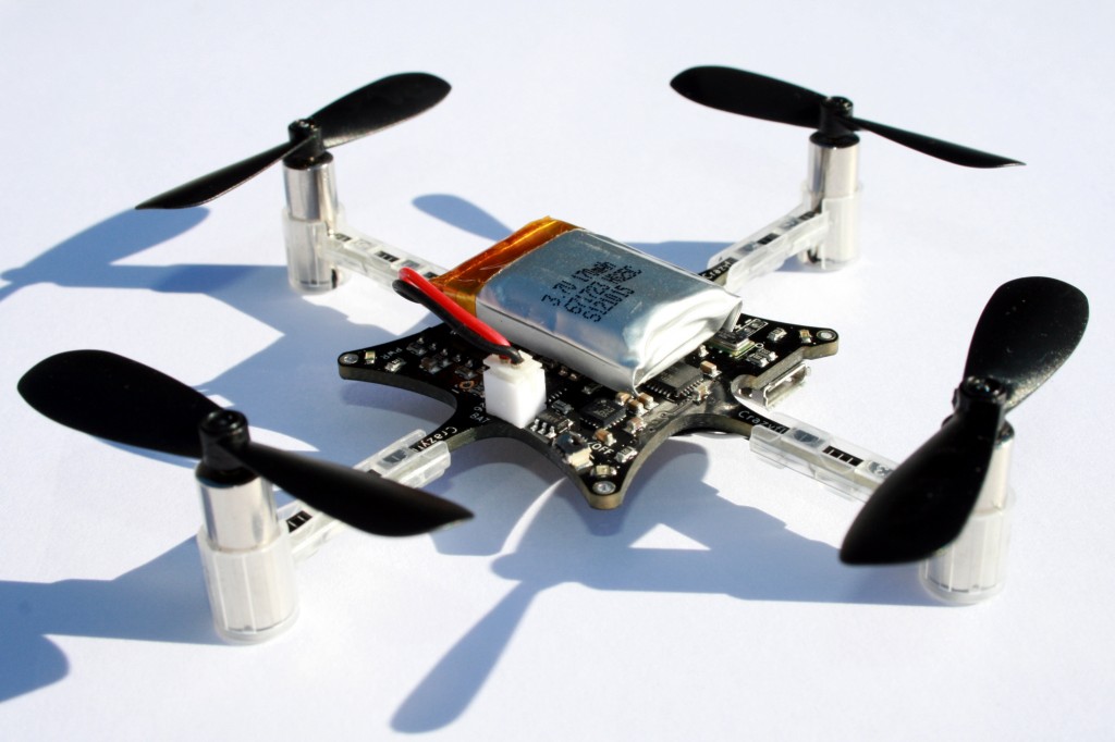
Assembled Crazyflie with new motor mounts
The pre-order shipments will start as announced, on Apr. 25th, and finish on Apr. 30th. Orders will be shipped out in the order they where placed so second batch orders will be shipped a bit earlier with the last order going out on Apr. 30th. Since Seeedstudio got a lot more pre-orders than expected, the first batch orders will need some more time for packaging and delivery and couldn’t all be shipped on Apr.25th, please understand.
Keep in mind that we are still doing development on both the firmware and software as well as continuously updating the wiki. So once you get your Crazyflie visit our page to get the latest updates and information on how to assemble the kit and start flying. Updating the firmware only takes a few minutes and you will get the latest features.
Thank you!
Bitcraze