When designing flying robots like drones it is important to be able to benchmark and test the propulsion system which in this case is a speed controller, motor and propeller. As we at Bitcraze are mainly working with tiny drones we need a thrust stand designed for small motors and propellers. We have actually already designed our own system identification deck, which can measure overall efficiency, thrust, etc., but is lacking the ability to measure torque. Torque is needed to be able to measure propeller efficiency which is now something we would like to measure. Before we developed the system-id deck we searched for of the shelf solutions that could satisfy our needs and could not find any. This still seems true, please let us know if that isn’t the case.
Expanding the system-id deck to measure torque doesn’t work and building something from scratch was a too big of a project for us. Next natural option would then be to modify an existing thrust stand and our choice fell for the tyro robotics 158X series.
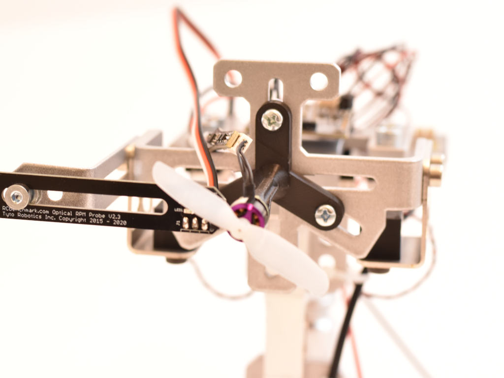
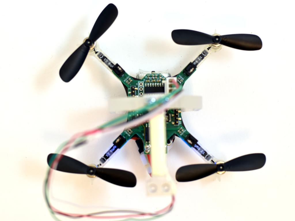
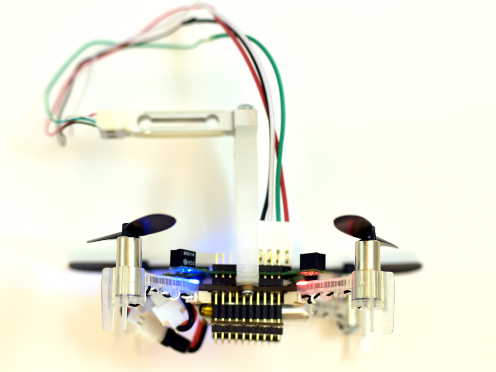
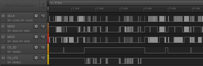
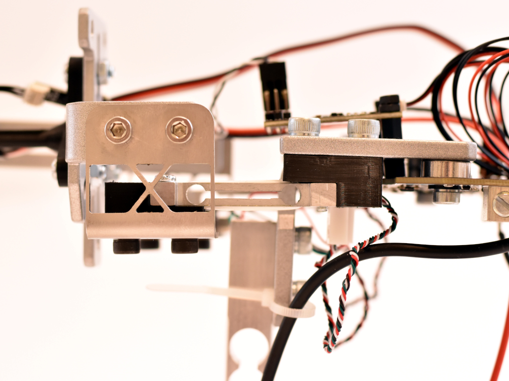
Looking at specifications, images and code we could figure out that replacing the load cells for more sensitive ones should be possible. The stock setup of 5kgf thrust and 2Nm of torque is just too much as we are looking for around 100 grams of thrust and around 10 mNm of torque. So we decided to give the replacement of load cells a shot! Assembly was quite smooth but we managed to break one of the surface mount load cell connectors off, luckily this was easily fixable with a soldering iron. With the stock setup we did some measurements with a 0802 11000KV brushless motor and a 55mm propeller in a pushing setup. It works but the measurements are noisy and repeatability is not great. Next thing would be to replace the load cells. The 158X uses TAL221 sized load cells which are available down to 1kg. We got those and with a calibration-allways-pass code we got from Tyto robotics we could make the calibration pass (note that modifying the thrust stand breaks the warranty). Now the thrust stability was much better but still the torque was a bit to noisy. We decided to go for even smaller thrust cells, the TAL220, and build 3D printable adapters to make them fit.
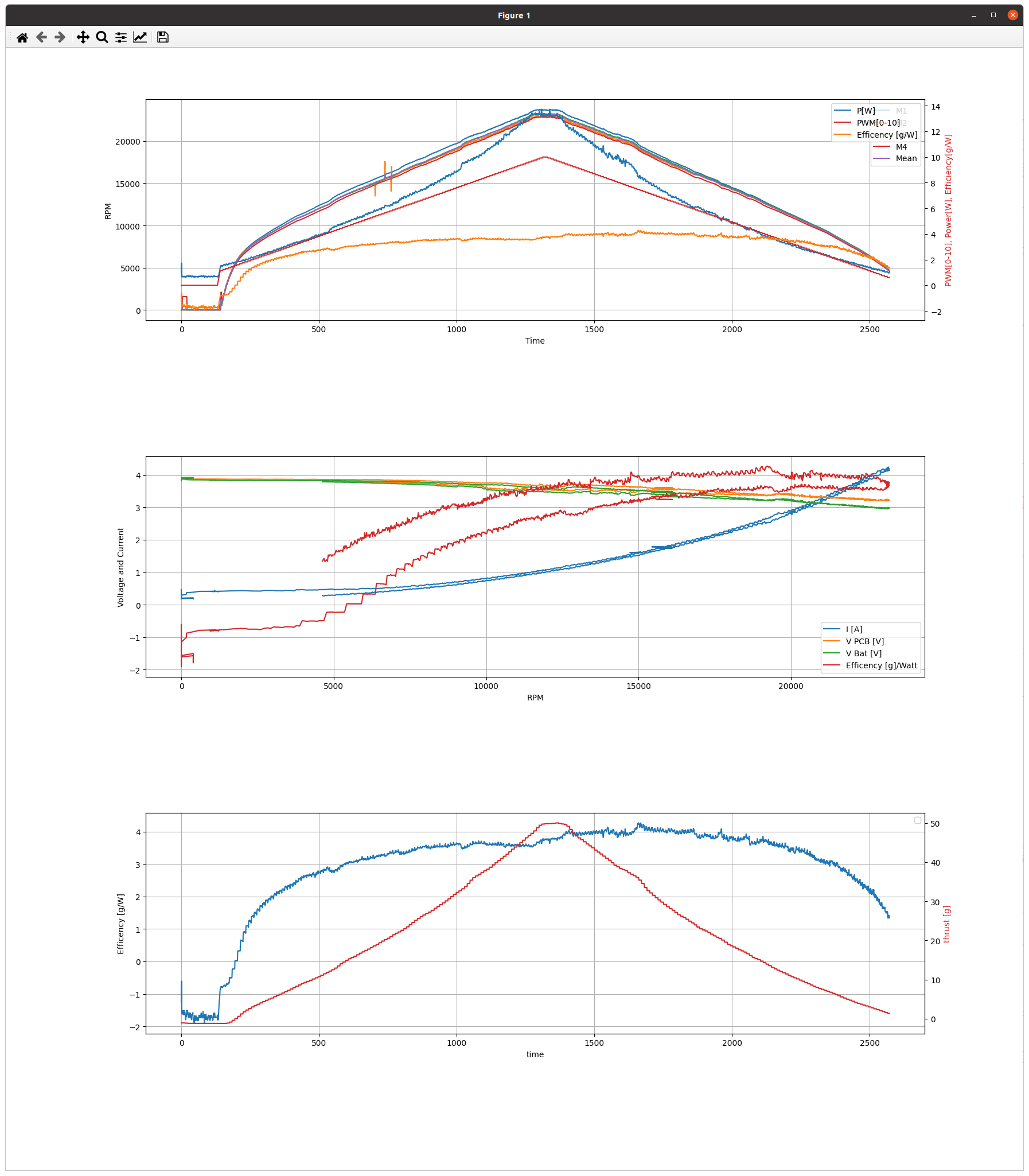
Now the torque noise level looked much better and so did the repeatability. By empirically measuring the thrust and torque using calibrated weights and by checking the measurements in RCBenchmark we got these values:
| Thrust, calibrated weight [g] | Measured [g] | Noise [g] |
| 200 | 200 | 1 |
| 100 | 100 | 1 |
| 50 | 50 | 0.5 |
| 20 | 20 | 0.5 |
| 10 | 10 | 0.5 |
| 0 | 0 | 0.5 |
| Torque, calibrated weight [g] | Measured [mNm] | Noise [mNm] |
| 200 | 257 | 2 |
| 100 | 128 | 1 |
| 50 | 64 | 0.3 |
| 20 | 25.7 | 0.3 |
| 10 | 12.7 | 0.3 |
| 0 | 0 | 0.2 |
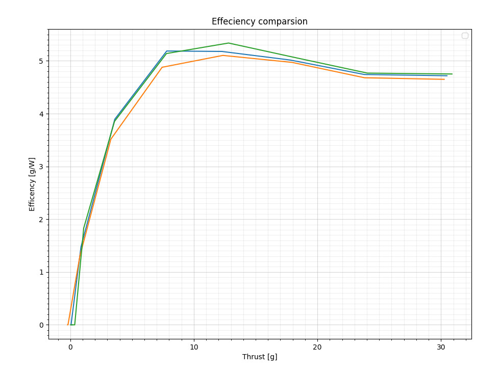
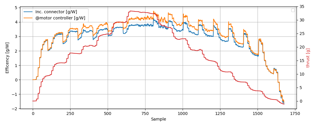
The thrust stand modification is still very fresh and we have to figure out some things but it all looks promising. For example we get 13% less overall efficiency when measuring it using our system-id thrust stand. Our guess is that it is due to that the Crazyflie arms in the system-id case blocks the airflow.
If you would like to do this modification yourself there are some simple instructions and STL files over at out mechanical github repository. Have fun!