Flying formations with a swarm is always fun to develop and watch, but it is also a great way to stress-test the software behind it. As part of the development of cflib2, we put it through one of its toughest tests yet: flying 49 Crazyflies in coordinated formations.
The entire swarm was controlled using a single Crazyradio 2.0, highlighting the combined improvements in cflib2 and Crazyradio firmware over the past few months.
The setup
The hardware configuration was relatively straightforward. We used 49 Crazyflie 2.1 Brushless drones, each one equipped with a bottom-mounted Color LED deck for vivid lighting effects. For positioning, we used the Lighthouse positioning system, covering the entire flight area, which was roughly 5x5x2m. Its accuracy allowed the Crazyflies to fly grid formations with just 0.4m spacing between them.
One of the big practical challenges when managing a large swarm is swapping the depleted batteries for charged ones. Thanks to the Crazyflie 2.1 Brushless PCB design, each drone can now charge while sitting on its charging dock, making it much easier to prepare the swarm for the next flight.
Flying the formations
The swarm performed a sequence of synchronized formations under the control of a central PC. Rather than streaming the full trajectories to every drone, the formations are built using the Crazyflie’s High-Level Commander. Each Crazyflie receives simple motion commands such as go to or spiral, and executes the corresponding trajectory onboard. At the same time, it receives commands for changing the color of the Color LED deck.
Using cflib2, these commands can be sent to all 49 Crazyflies through a singe Crazyradio 2.0, which was not possible with cflib.
Looking ahead
This demonstration is an exciting milestone for cflib2 and showcases what the new library makes possible. While controlling 49 Crazyflies is an impressive demonstration, cflib2 is designed to benefit projects of every size. Whether you are flying a single Crazyflie or coordinating a large swarm, the goal is to provide a faster, more scalable, and more robust communication library.
Most of the functionalities from cflib have already been migrated to cflib2, and development is continuing. For many applications, cflib2 is already ready to use, so if you would like to try it out, you can find the repository here.
ICRA 2026 has wrapped up, and we’re back from a fantastic week in Vienna! Booth 91 was busy from start to finish, and we wanted to put together a short highlight video to share some of what happened — for everyone who stopped by, and for everyone who couldn’t make it this year.
The Swarm Demo
At the center of our booth was our live autonomous swarm demo — multiple Crazyflies flying autonomously in a controlled indoor environment, with everything tracked, repeatable, and stable across runs. We also could play around with our Lighthouse wand – which was also a great solution for troubleshooting the few misbehaving drones we had during those 3 days.
SwarmGPT, Live and Interactive
One of the highlights of the week was demonstrating SwarmGPT together with the Learning Systems and Robotics Lab (LSY) at the Technical University of Munich. SwarmGPT explores a simple but powerful idea: instead of hand-coding trajectories, you describe the intent — pick a piece of music, prompt a style or expression — and the system handles the planning and safety while the swarm performs it.
This time around, we brought a more interactive version of the demo than our end-of-year collaboration a few months back, and visitors got to try it out for themselves at the booth. Watching people prompt the swarm and then watch their idea come to life in the air was a great reminder of how far natural-language interfaces have come, and how much room there still is to explore in this space.
Research We Saw on the Crazyflie
Beyond our own demos, one of our favorite parts of ICRA is talking with our users and seeing what the community has built. This year was no exception — we spotted Crazyflies appearing in research spanning multi-agent coordination, modular micro-UAVs designed for autonomous mid-air docking, and decentralized swarm control approaches where each drone makes its own decisions based on local information rather than a central planner. Some examples include:
It’s always a bit surreal to see the same small quadcopter we ship from our office end up at the center of such different research questions — from choreography and language-driven control, to docking and modular hardware, to fully decentralized swarms. If you presented work involving the Crazyflie this year, thank you for stopping by and sharing it with us — and if you left a poster behind, it’s already found a home on our office wall.
Thanks for Stopping By
ICRA continues to be one of our favorite events of the year, not just for the demos, but for the conversations. Someone describes a challenge they’re running into in their lab, and a few months later, that conversation has often turned into a feature, a library improvement, or a new piece of hardware. If you stopped by booth 91, told us about your research, or just said hello, thank you. We’re already looking forward to the next one!
If you’d like to dig deeper into any of what’s shown in the video, or want to get started with the Crazyflie yourself, head over to bitcraze.io or reach out at contact@bitcraze.io.
Some Fun-Friday projects begin with a clear goal and a straight path to the finish line. The best ones, however, take you somewhere completely unexpected.
This project originally set out to build a device for determining spatial coordinates within a Lighthouse-covered flight area. Instead, it evolved into the Lighthouse Wand, a hand-held “magic wand” letting you grab and move drones in 3D space just by pointing at them.
How it works
The Wand is a Crazyflie platform with a Lighthouse positioning deck. That’s enough for it to know its own position and orientation in the room. When the button is pressed, it starts broadcasting those 6 numbers over Peer to Peer radio.
Any Crazyflie/receiver in the room on the same radio channel, listens to those packets and runs a simple “grasping” algorithm: while the wand line (positive x-axis) passes close enough to the drone, it builds up a confidence score. Once the score crosses a threshold, the drone is considered grasped. From that point on, it just keeps a specific distance from the wand, while being on the wand line.
When the button is released, the grasped drone either hovers in place, or lands, depending on the release height.
The Color LED deck on the receiver drone, gives you visual feedback: yellow while the Crazyflie is building up its confidence score, green when it’s grasped, and red when it’s landing.
A big advantage of this system is that all interactions run entirely onboard the Crazyflies, allowing them to operate without relying on the cfclient or cflib during flight.
The hardware design
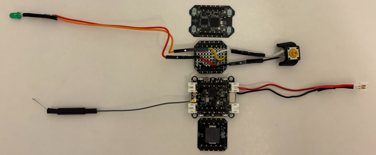
The wand is a Crazyflie Bolt 1.1 with a Lighthouse positioning deck and a Buzzer deck for audio feedback. To allow for user input, I created a simple “Button deck” based on the Prototyping deck utilizing the GPIO pins of the Crazyflie. It also includes an LED for visual feedback when the button is pressed.
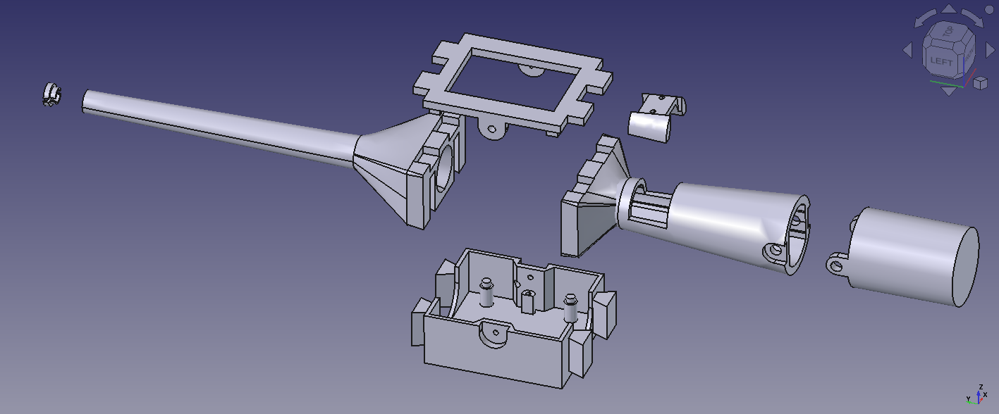
The casing is fully 3D printed in PLA and was designed to give the device a more wand-like feel in the hand. Its shape also makes it easier to hold, aim, and use intuitively during interaction.
The firmware design
Both the Wand and the receiver are firmware apps created on top of the crazyflie-firmware. In the design that I followed, there is a clean separation between the two parties. The wand is a pure broadcaster: it only reads its own pose and transmits it. All grasping logic and flight control run independently on each receiver. Since each receiver is fully autonomous, the system scales to any number of drones with no extra load on the wand.
Where to find the Lighthouse Wand?
A version of the Lighthouse wand is now integrated in our decentralized swarm demo, where it can be used to interact with multiple drones, while the collision avoidance algorithms are still on. This system was first showcased at the European Robotics Forum 2026 in Stavanger, and we’ll also be bringing it to ICRA 2026. If you’re there, stop by booth 91and try flying a bunch of Crazyflies yourself using the wand.
You can find the complete Lighthouse Wand project in this repository. It contains the firmware, the hardware files, and detailed documentation to build and experiment with the wand yourself.
At Bitcraze, we spend a lot of time making things fly. Even though flying robots are, and will always be, fascinating to watch , every now and then it’s refreshing to try something different. Last Friday, I started exploring an idea that has been lying around for a while now: having a ground robot with the same Crazyflie infrastructure – the radio communication, the deck ecosystem and the cfclient connection. This robot is also known as the Crazyrat.
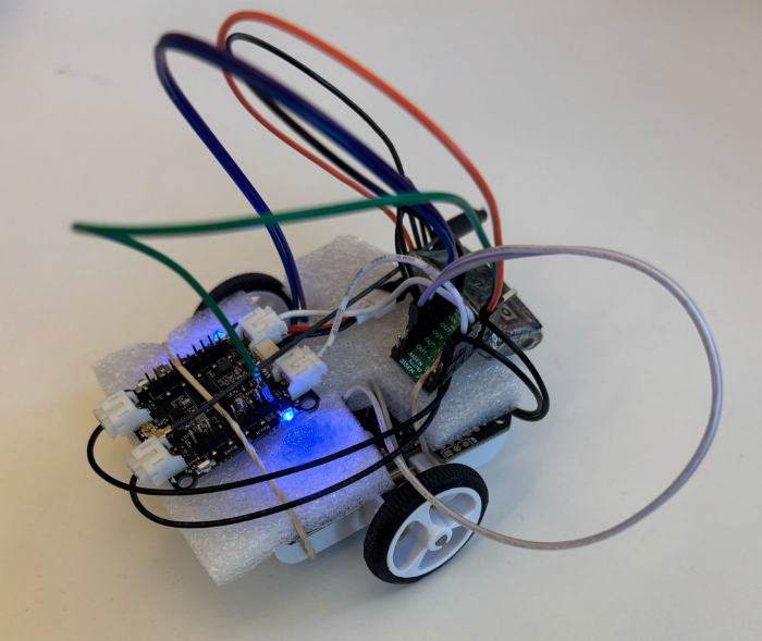
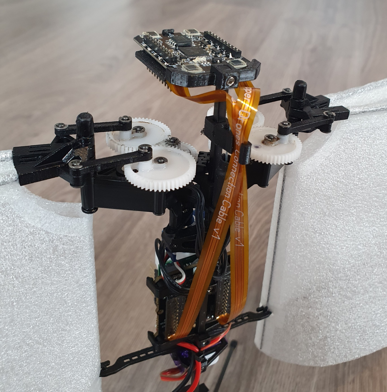
Fair warning: this is a first prototype, and it definitely looks like one. Jumper wires going in every direction, plastic foam and rubber bands to keep everything in place. But it drives, and it drives fast! That’s enough to call it a success and write about it.
Hardware
The entire vehicle was built around the Crazyflie Bolt 1.1, using its motor connectors, and specifically the S pins to drive a small H-bridge motor driver, enabling proper bidirectional DC motor control. To make it possible to drive the H-bridge, the motors must be configured as brushed.
For the motor driver, I used a Pololu DRV8833 Dual Motor Driver Carrier. I experimented with two different motor sets: one with a 75:1 gear ratio and one with 15:1. Even though the 75:1 motors offered better precision and were easier to drive, the 15:1 setup was the clear winner due to their speed.
The motors, the chassis and the power supply were taken from a Pololu 3pi+ robot.
Firmware
For the firmware, I used the Out-Of-Tree functionality of the crazyflie-firmware which makes it easy to integrate custom controllers. The controller itself is relatively simple. It maps pitch and yaw commands sent from the cfclient to throttle and steering respectively. Then, it sends the calculated values directly to the motors as PWM signals.
To test the prototype, I used a gamepad and drove it through the cfclient – no modifications are required. Here’s a video showing the capabilities of the Crazyrat using the 15:1 motor setup.
What’s Next
This project was a really fun learning experience on the potential and the limitations of the ground robots. These are some of the directions I plan to explore in the future:
Robust design – Design a proper chassis, clean up the wiring and make the whole vehicle smaller, to fit better in the Crazyflie ecosystem.
Deck integration – Use either the Lighthouse or the LPS deck for positioning and the Multi-Ranger deck for obstacle detection.
Experiment – Explore heterogeneous multi-agent swarming scenarios with the Crazyrat and the Crazyflie.
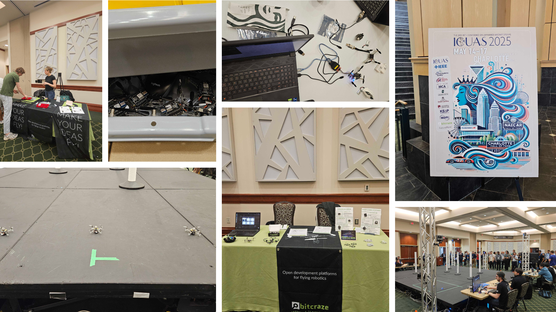
As we mentioned in a previous blog post, the last couple of weeks have been full of exciting events in the US. We first began our adventure in Charlotte, North Carolina, where we attended the International Conference on Unmanned Aircraft Systems (ICUAS), as platinum sponsors.
We were especially thrilled to be involved because the final stage of the conference’s competition featured Crazyflies, which played a central role in the challenge.
The ICUAS UAV Competition
This year’s competition simulated a search mission in an urban environment. The goal was for teams to identify ArUco markers placed on multiple obstacles, while maintaining line-of-sight and communication among a swarm of three Crazyflies.
Each team’s UAVs launched from a designated base, navigated a known environment, and attempted to locate several targets. The drones relied on an OptiTrack system for positioning and used the AI deck as a camera for image recognition. Constant communication between the base and all UAVs was required throughout the mission.
The event, organized by the LARICS team, combined both simulation and real-world implementation. Their hard work ensured that competitors could smoothly transition their systems from digital models to actual flying drones. What followed was an intense and fun two-day hackathon.
Although the ICUAS UAV Competition drew interest from 26 teams globally, only five finalist teams made it to Charlotte to run their scenarios with real drones. In the end, it was Team Aerial Robotics from the Indian Institute of Technology Kanpur (IITK) who took home first place—congratulations to them!
While the event went smoothly overall, some communication challenges cropped up—solved creatively by placing a radio in the center of the arena. Battery management was also key, with fully charged packs being a hot commodity to maximize flight time.
Research and Presentations
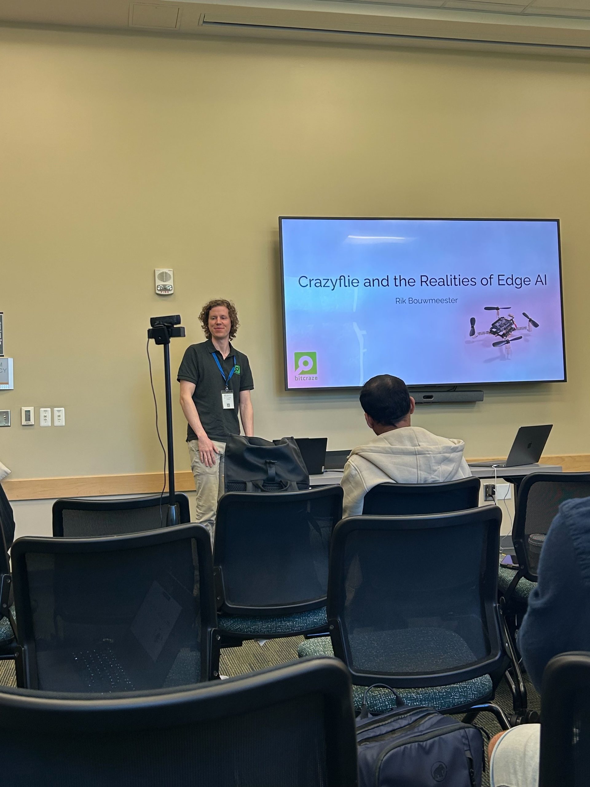
Alongside the competition, the conference featured a wide range of research presentations. We were proud to see Rik present on the AI deck during a workshop focused on embodied AI.
One of the highlights was the Best Paper Award, which—although we missed the talk, was awarded to a team from Queen’s university using the Crazyflie to simulate drone landings on ocean waves. You can read their fascinating paper here: https://arxiv.org/abs/2410.21674
Final Thoughts
Overall, ICUAS 2025 was a great experience—full of innovation, collaboration, and of course, plenty of flight time. We’re grateful to the organizers, competitors, and everyone who stopped by our booth. Until next time!
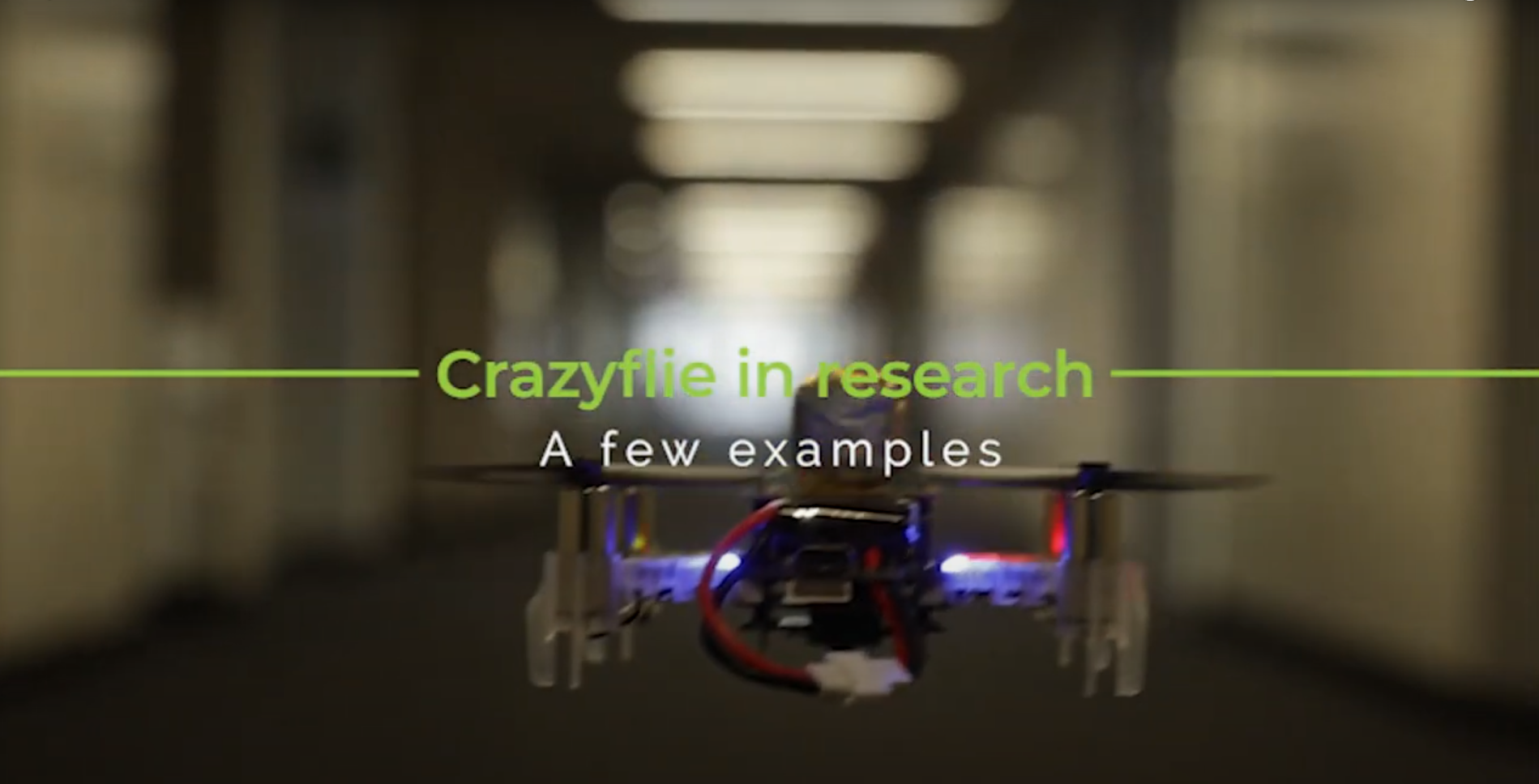
It’s now become a tradition to create a video compilation showcasing the most visually stunning research projects that feature the Crazyflie. Since our last update, so many incredible things have happened that we felt it was high time to share a fresh collection.
As always, the toughest part of creating these videos is selecting which projects to highlight. There are so many fantastic Crazyflie videos out there that if we included them all, the final compilation would last for hours! If you’re interested, you can find a more extensive list of our products used in research here.
The video covers 2023 and 2024 so far. We were once again amazed by the incredible things the community has accomplished with the Crazyflie. In the selection, you can see the broad range of research subjects the Crazyflie can be a part of. It has been used in mapping, or swarms – even in heterogeneous swarms! With its small size, it has also been picked for human-robot interaction projects (including our very own Joseph La Delfa showcasing his work). And it’s even been turned into a hopping quadcopter!
Here is a list of all the research that has been included in the video:
Energy efficient perching and takeoff of a miniature rotorcraft Yi-Hsuan Hsiao, Songnan Bai, Yongsen Zhou, Huaiyuan Jia, Runze Ding, Yufeng Chen, Zuankai Wang, Pakpong Chirarattananon City University of Hong Kong, Massachusetts Institute of Technology, The Hong Kong Polytechnic University
But enough talking, the best way to show you everything is to actually watch the video:
A huge thank you to all the researchers we reached out to and who agreed to showcase their work! We’re especially grateful for the incredible footage you shared with us—some of it was new to us, and it truly adds to the richness of the compilation. Your contributions help highlight the fantastic innovations happening within the Crazyflie community. Let’s hope the next compilation also shows projects with the Brushless!
A few weeks ago, the prestigious Robotics: Science and Systems (RSS) conference was held at Delft University of Technology. We helped with the co-organization of a half-day tutorial and workshop called “Aerial Swarm Tools and Applications” so Kimberly (I) was there on behalf of both Bitcraze and Crazyswarm2. In this blog post, we will tell you a bit about the conference itself and the workshop (and perhaps also a tiny bit about RoboCup)
The Robotics: Science and Systems conference
The Robotics: Science and Systems conference, also known as RSS, is considered one of the most important robotics conferences to attend, alongside ICRA and IROS. It distinguishes itself by having only a single track of presented papers, which makes it possible for all attendees to listen to and learn about all the cool robotics work done in a wide range of fields. It also makes it more difficult to get a paper accepted due to the fixed number of papers they can accept, so you know that whatever gets presented is of high quality.
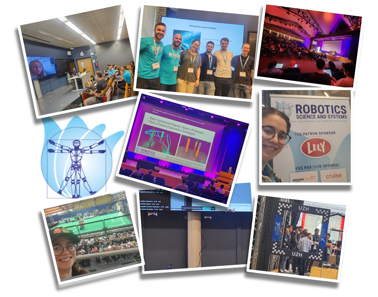
This year the topic was very much on large language models (LLMs) and their application in robotics, most commonly manipulators. Many researchers are exploring the ways that LLMs could be used for robotics, but that means not a lot of small and embedded systems were represented in these papers. We did find one paper where Crazyflies were presented, namely the awesome work by Darrick et al. (2024) called ‘Stein Variational Ergodic Search’ which used optimal control for path planning to achieve the best coverage.
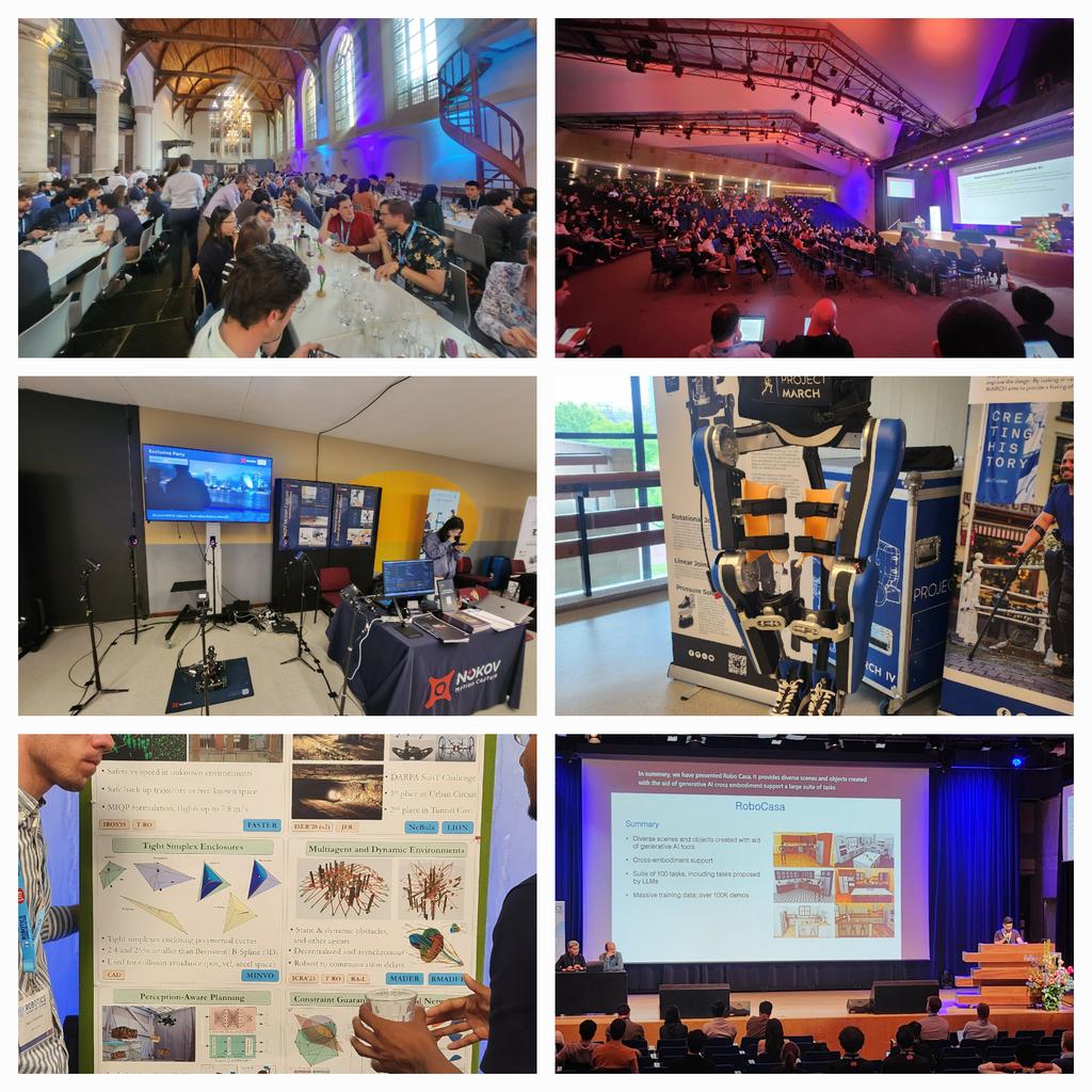
It gave us the chance to experience many of the other works that could be found at RSS. One in particular was about the robotic design of the cute little biped from Disney Imagineering named “Design and Control of a Bipedal Robotic Character” by Grandia et al. (2024). Also very impressive was the Agile flight demo by the group of Davide Scaramuzza, and we enjoyed listening to the keynote by Dieter Fox, senior director at Nvidia, talking about ‘Where is RobotGPT?’. The banquet location was also very special, as it was located right in the old church of Delft.
The main reason we joined RSS was that we were co-organizing the workshop ‘Aerial Swarm Tools and Applications’. This was done in collaboration with Wolfgang Hönig from Crazyswarm2/TU Berlin, Miguel Fernandez Cortizas and Rafel Perez Segui from Aerostack2/Polytechnic University of Madrid (UPM), and Andrea Testa, Lorenzo Pichierri, and Giuseppe Notarstefano from CrazyChoir/University of Bologna. The workshop was a bit of a hybrid as it contained both talks on various aerial swarm applications and tutorials on the different aerial swarm tools that the committee members were representatives of.
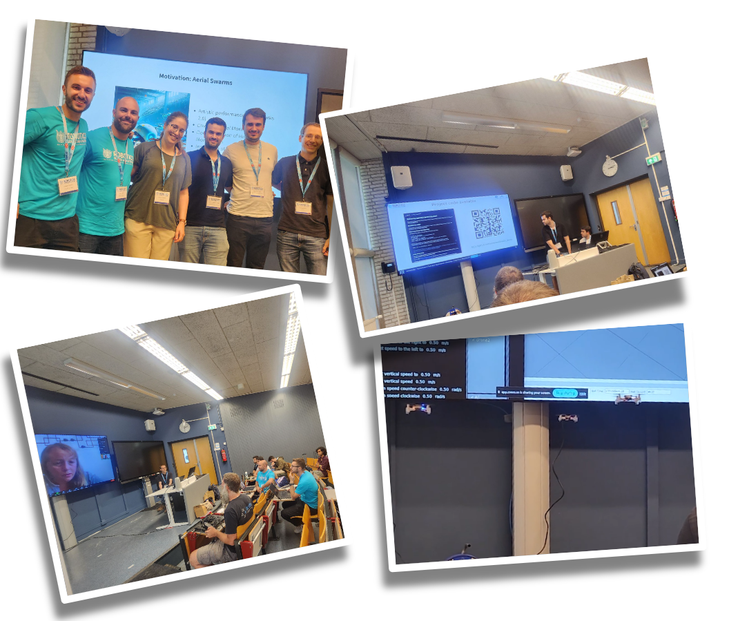
Photos of the Aerial Swarm Tools and Applications workshop
Sabine Hauert from the University of Bristol started off the workshop by talking about “Trustworthy swarms for large-scale environmental monitoring.” Gábor Vásárhelyi from Collmot Robotics and Eötvös University gave a talk/tutorial about Skybrush, showing its suitability not only for drone shows but also for research (Skybrush was used for the Big Loco Test show demo we did 1.5 years ago). The third speaker was SiQi Zhou, speaking on behalf of Angela Schöllig from TU Munich, discussing “Safe Decision-Making for Aerial Swarms – From Reliable Localization to Efficient Coordination.” Martin Saska concluded the workshop with his talk “Onboard relative localization for agile aerial swarming in the wild” about their work at the Czech TU in Prague. They also organize the Multi-robot systems summer school every year, so if you missed it this year, make sure to mark it in your calendar for next summer!
We had four tutorials in the middle of the workshop as well. Gábor also showed Skybrush in simulation after his talk for participants to try out. Additionally, we had tutorials that included real, flying Crazyflies live inside the workshop room! It was a bit of a challenge to set up due to the size of the room we were given, but with the lighthouse system it all worked out! Miguel and Rafael from Aerostack2 were first up, showing a leader-follower demo. Next up were Wolfgang and Kimberly (Crazyswarm2) who showed three Crazyflies collaboratively mapping the room, and finally, Andrea and Lorenzo from CrazyChoir demoed formation control in flight.
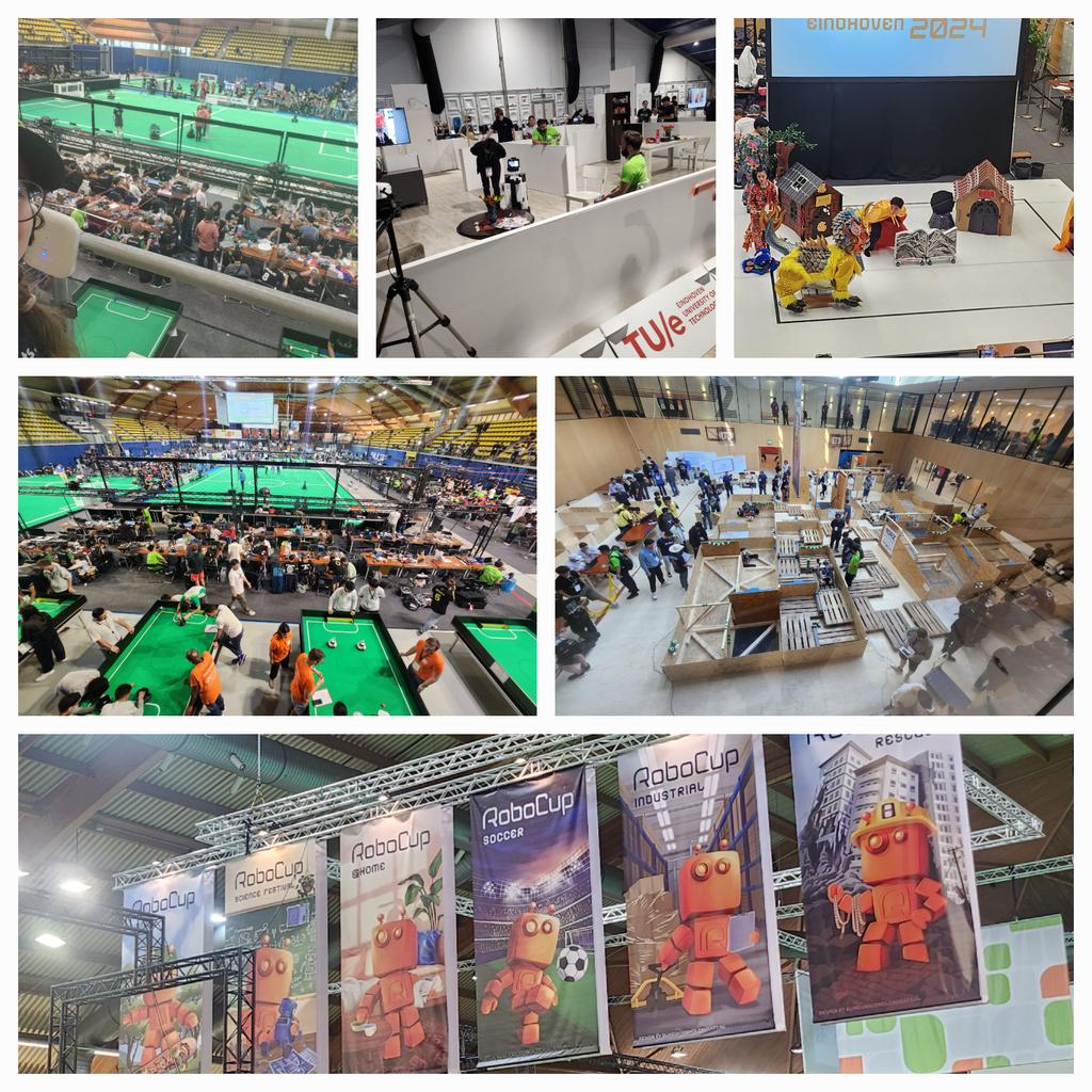
Luckily, there was also a bit of time to visit Eindhoven for a field trip to the 2024 edition of the world championship competitions of RoboCup! This is a very large robotics competition held in several different divisions, namely Soccer (with many subdivisions), Industrial, Rescue, @Home, and Junior. Each country usually has its own national championships, and those that win there can compete in the big leagues at events like these. RoboCup was extremely fun to attend, so if any robotics enthusiasts happen to live close to one of these, go! It’s awesome.
Photos of the field trip to RoboCup
Maybe drone competitions might be one of RoboCup’s divisions in the future :)
It’s not often a blog post happens on the 25th of December, so this time, you’re having a treat with some new Bitcraze prototypes as a present from us! If you have time to get away from the Christmas table, there’s something we’d love you to watch:
Now let’s try to see if you noticed all the new stuff you see in this video!
Our new flight lab
We teased it, but in the beginning of December, we got our extended flight lab! We added 110 m2 to our flight space. It was a rush to have everything ready for the video – we cleaned everything, painted the walls and the green logo, set up the positioning system without our truss… But now we’re happy to show you how big the space is! Even if it’s hard to convey the real size on camera.
The Crazyflie 2.1 brushless
We already talked about it in this blog post, but the brushless has made significant progress and we feel confident that you will get your hands on it in 2024. Here, we use the extra power for a fast and agile flight. It also was very stable and didn’t crash once during the shooting!
The Lighthouse V2
Yes, you counted right! The Brushless flew with 16 base stations! We’ve worked really hard this past three months to create a new Lighthouse deck – the Lighthouse deck 2.0. It could get its position from 16 base stations. That’s 4 times more than what was previously possible! It behaved consistently well during the different tries, and we are really happy with the result. Right now, it’s just a prototype, but we’re hoping to get it to the next step in the coming months.
The contact charging station
Marcus created a power charger for the Brushless that doesn’t need any extra deck to allow for charging. It connects with the brushless feet. It has also the cool feature of changing LEDs indicating the status (idle, charging or charged). It is also a prototype, and we don’t know if this will end up being a product
The high-power LED
This is trickier to see, but it’s not our usual LED ring that the brushless carries. It’s a new, powerful LED underneath. It is so powerful that it nearly blinded us when we tried it for the first time. We put a diffuser on it, and it allowed the Crazyflie to be visible at such a high pace! This is a prototype too of course and we’re not sure if we will release it, but it’s fun to use for this kind of project.
Other announcements
During this week, our office is closed- we take this week to celebrate and rest a little before 2024. This means that shipping and support will be greatly reduced.
But we’re back the week after- at a somewhat reduced pace though. The developer meeting on the 3rd of January is maintained but without any presentation. We’ll take this time to answer any questions you have and talk a little! The details are here.
Bitcraze got their presents this year: a handful of working prototypes! We hope we got your wishes too, merry Christmas to you!
The Flow deck has been around for some time already, officially released in 2017 (see this blog post), and the Flow deck v2 was released in 2018 with an improved range sensor. Compared to MoCap positioning and the Loco Positioning System (based on Ultrawideband) that were already possible before, optical flow-based positioning for the Crazyflie opened up many more possibilities. Flight was no longer confined to lab environments with set-up external systems; people could bring the Crazyflie home and do their hacking there. Moreover, doing research for exploration techniques that cannot rely on external positioning systems was possible with it as well. For example, back in my day as a PhD student, I relied heavily on the Flow deck for multi-Crazyflie autonomous exploration. This would have been very difficult without it.
However, despite the numerous benefits that the Flow deck provides, there are also several limitations. These limitations may not be immediately familiar to many before purchasing a Crazyflie with a Flow deck. A while ago, we wrote a blog post about positioning systems in general and even delved into the Loco Positioning System in detail. In this blog post, we will explore the theory of how the Flow deck enables the Crazyflie to fly, share general tips and tricks for ensuring stable flight, and highlight what to avoid. Moreover, we aim to make the Flow deck the focus of next week’s Developer meeting, with the goal of improving or clarifying its performance further.
Theory of the Flow deck
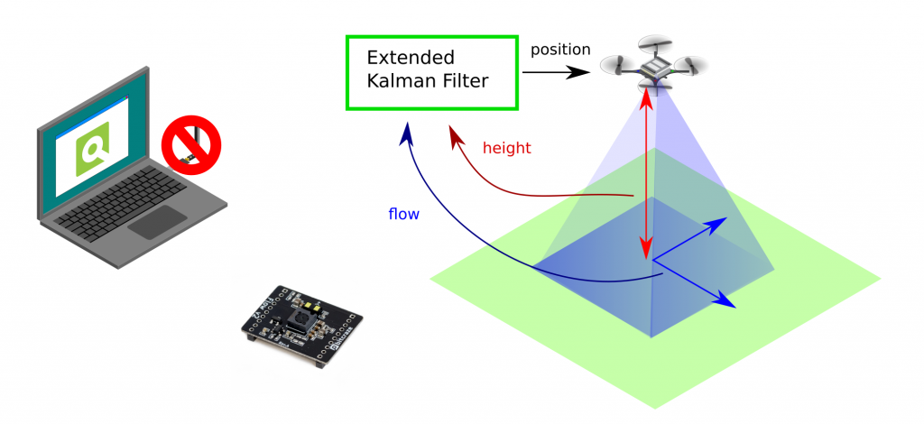
I won’t delve into too much detail but will provide a generic indication of how the Flow deck works. As previously explained in the positioning system blog post, the Flow deck is a relative positioning system with onboard estimation. “Relative” means that wherever you start is the (0, 0, 0) position. The extended Kalman filter processes flow and height information to determine velocity, which is then integrated to estimate the position—essentially dead reckoning. The onboard Kalman filter manages this process, enabling the Crazyflie to use the information for stable hovering.
The optical flow sensor (PMW3901) calculates pixel flow per frame (this old blog post explains it well), and the IR range sensor (VL53L1x) measures height up to 4 meters (under ideal conditions). The Kalman filter incorporates a measurement model that describes the relationship between these two values and the velocity of the Crazyflie. More detailed information can be found in the state estimation documentation. This capability allows the Crazyflie to hover, as explained in the getting started tutorial.
If you want to fly with the Crazyflie and the Flow deck, there are a couple of things to take in mind:
Take off from a floor with texture. Natural texture like wood flooring is probably the best.
The floor shouldn’t be too shiny, and be aware of infrared scattering for the height sensor
The room should be well-lit, as the sensor needs to see the texture.
There are certain situations that the Flow deck has some issues with:
Low or no texture. Flying above something that is only one plain color
Black areas. Similar reason to flying above no texture, but it’s more difficult than usual. Especially with startup, the position estimate diverges
Low light conditions
Flying over its own shadow
We made a video that shows these types of behaviors, starting of course with the most ideal flying conditions:
Moreover, it is also important to note that you shouldn’t fly too high or yaw too often. The latter will make the Crazyflie drift, as the optical flow cannot be distinguished as being caused by the yaw movement.
Developer meeting about Flow deck
We believe that many of the issues people experience are primarily due to the invisibility of the positioning quality. In many of our examples, the Crazyflie will not take off if the position is stable. However, we don’t have a corresponding functionality in our CFclient, as it is more up to the user to recognize when the positioning is diverging. There is a lot of room for improvement in this regard.
This is the reason why the next developer meeting will specifically focus on the Flow deck, which will be on Wednesday the 6th of December, 3 pm central European time. During the meeting, we will explain more about the Flow deck, discuss the issues we are facing, and explore ways to enhance the visibility of positioning quality. Check out this discussion thread for information on how to join.
This week’s guest blogpost is from Matěj Karásek from Flapper Drones, about flying the Nimble + with a positioning system. Enjoy!
Flapper Drones are bioinspired robots flying by flapping their wings, similar to insects and hummingbirds. If you haven’t heard of Flappers yet, you can read more about their origins at TU Delft and about how they function in an earlier post and on our company website.
In this blogpost, I will write about how to fly the Flappers (namely the Flapper Nimble+) autonomously within a positioning system such as the Lighthouse, and will of course include some nice videos as well.
The Flapper Nimble+ is the first hover-capable flapping-wing drone on the market. It is a development platform powered by the Crazyflie Bolt and so it can enjoy most of the perks of the Crazyflie ecosystem, including the positioning systems as well as other sensors (check this overview). If you would like to get a Flapper yourself, just head to the Bitcraze webstore, where there are some units ready to be shipped! (At the time of writing at least…)
Minimal setup
The minimal setup for flying in a positioning system is nearly identical as with a standard Crazyflie. Next to a Flapper with a recent firmware, a Crazyradio dongle, a positioning system (in this post we will use the Lighthouse), and a compatible positioning deck (Lighthouse deck) you will also need: 1) a mount, such that the deck can be attached on top of the Flapper, and 2) a set of extension cables. You can 3D print the mounts yourself (models here), the extension cable prototypes can either be inquired from Flapper Drones, or can be soldered by yourself (in that case, the battery holder deck, standard Crazyflie pin headers and some wires come handy). Just pay attention to connect the cables in the correct way, as if the deck was mounted right on top of the Bolt. The complete setup with the Lighthouse deck will look like this:
Lighthouse deck installation on a Flapper Nimble+. Make sure the extension cables are well secured (e.g. by using the additional cable mount) such they don’t get caught by the gears.
For the Lighthouse, as with regular Crazyflies, the minimum number of base stations (with some redundancy) is 2, but you will get larger tracking volume with more base stations. 4 base stations mounted at 3 m height will give you about 5 meters time 5 meters coverage, which is recommended especially if you want to fly more than 1 Flapper at a time (they are a bit larger than the Crazyflies, after all…). From now on, it is exactly the same as with standard Crazyflies. After you calibrate the Lighthouse system using the standard wizard procedure via the Cfclient, you can just go to the Flight Control Tab and use the “Command Based Flight Control” buttons to take-off, command steps in xyz directions and land. It is this easy!
Flapper Nimble+ in Lighthouse flown via Command Based Flight Control of cfclient
Assisted flight demo
We used this setup in February for the demos we were giving at the Highlight Delft festival in the Netherlands. This allowed people with no drone piloting skills (from 3-year-olds, to grandmas – true story) fly and control the Flapper in a safe way (safe for the Flapper, as the Flapper itself is a very safe platform thanks to its soft wings and low weight). To make it more fun, and even safer for the Flapper, we used a gamepad instead of on screen buttons, and we modified the cfclient slightly such that the flight space can be geofenced to stay within the tracking volume.
Flight demo at Highlight Delft festival, using the Lighthouse and position hold assistance
If you would like to try it yourself (it works also with standard crazyflies), the source code is here (just keep in mind it is experimental and has some known bugs…). To fly in the position-assisted mode, you need to press (and keep pressing) the Alt 1 button, and use the joysticks to move around (velocity commands, headless mode). Releasing the Alt 1 button will make the Flapper autoland. Autoland will also get triggered when the battery is low. You can still fly the Flapper in a direct way when pressing Alt 2 instead.
Flying more Flappers at a time
Again, this is something that works pretty much out of the box. As with a regular crazyflie, you just need to assign a unique address to each of the Flappers and then use e.g. this example python script to run a preprogrammed sequence.
With a few extra lines of code, we pulled this quick demo at the end of the Highlight Delft festival, when we had 30 minutes left before packing everything (one of the Flappers decided to drop its landing gear, probably too tired after 3 evenings of almost continuous flying…):
Sequence with 3 Flappers within Lighthouse positioning system
Other positioning systems
Using other positioning systems is equally easy. In fact, for the Loco Positioning system, the deck can even be installed directly on the Flapper’s Bolt board (no extension cables or mounts are needed). As for optical motion tracking, we do not have experience with Qualisys and the active marker deck, but flying with retro-reflective markers within OptiTrack system can be setup easily with just a few hacks.
When choosing and setting up the positioning system, just keep in mind that due to its wings, the Flapper needs to tilt much more to fly forward or sideways, compared to a quadcopter. This is not an issue with the Loco Positioning system (but there can be challenges with position estimation, as described further), but it can be a limitation for systems requiring direct line of sight, such as the Lighthouse or optical motion tracking.
Ongoing work
In terms of control and flight dynamics, the Flapper is very different from the Crazyflie. Thus, for autonomous flight, there remains room for improvement on the firmware side. We managed to include the “flapper” platform into the standard Crazyflie firmware (in master branch since November 2022, and in all releases since then), such that RC flying and other basic functionality works out of the box. However, as many things in the firmware were originally written only for a (specific) quadcopter platform, the Crazyflie 2.x, further contributions are needed to unlock the full potential of the Flapper.
With the introduction of “platforms” last year, many things can be defined per platform (e.g. the PID controller gains, sensor alignment, filter settings, etc.), but e.g. the Extended Kalman filter, and specifically the motion model inside, has been derived and tuned for the Crazyflie 2.x, and is thus no representative of the Flapper with very different flight dynamics. This is what directly affects (and currently limits) the autonomous flight within positioning systems – it works well enough at hover and slow flight, but the agility and speed achievable in RC flight cannot be reached yet. We are planning to improve this in the future (hopefully with the help of the community). The recently introduced out of tree controllers and estimators might be the way to go… To be continued :)
Thanks Matej ! And for those of you at home, don’t forget that we have our dev meeting next Wednesday (the 5th), where we’ll discuss about the Loco positioning system, but also will take some time for general discussions. We hope to see you there!