One feature of the new Crazyflie 2.0 that we are especially happy about is the new expansion port. We have attached a lot of hardware to the current Crazyflie and we have also seen lots of users attaching their hardware, but it’s not very easy. The current connector is small, you will need to solder and it’s not mechanically stable once you attach something. For the Crazyflie 2.0 we wanted to improve this, making it easier to attach new hardware and to expand the functionality of the platform. When we started looking at this we quickly realized that the small size of our platform limits what kind of interface we can have. We wanted something very small and light, but still it couldn’t be too expensive. While looking for a solution we found some of good alternatives, until you start measuring them and bringing them into our design in KiCad (again, it’s like parking a minivan in your bedroom). Something that didn’t make the selection easier was that we wanted lots of flexibility. We wanted users to be able to add multiple boards, both on the bottom and on the top of the platform. This might sound crazy for a small platform like the Crazyflie, but with the new motors we are able to carry more weight than before. Adding expansion boards will of course effect performance (like flight time) but to the extent that it’s possible, we want to give users the possibility to do as much crazy things as possible with their Crazyflies :-)
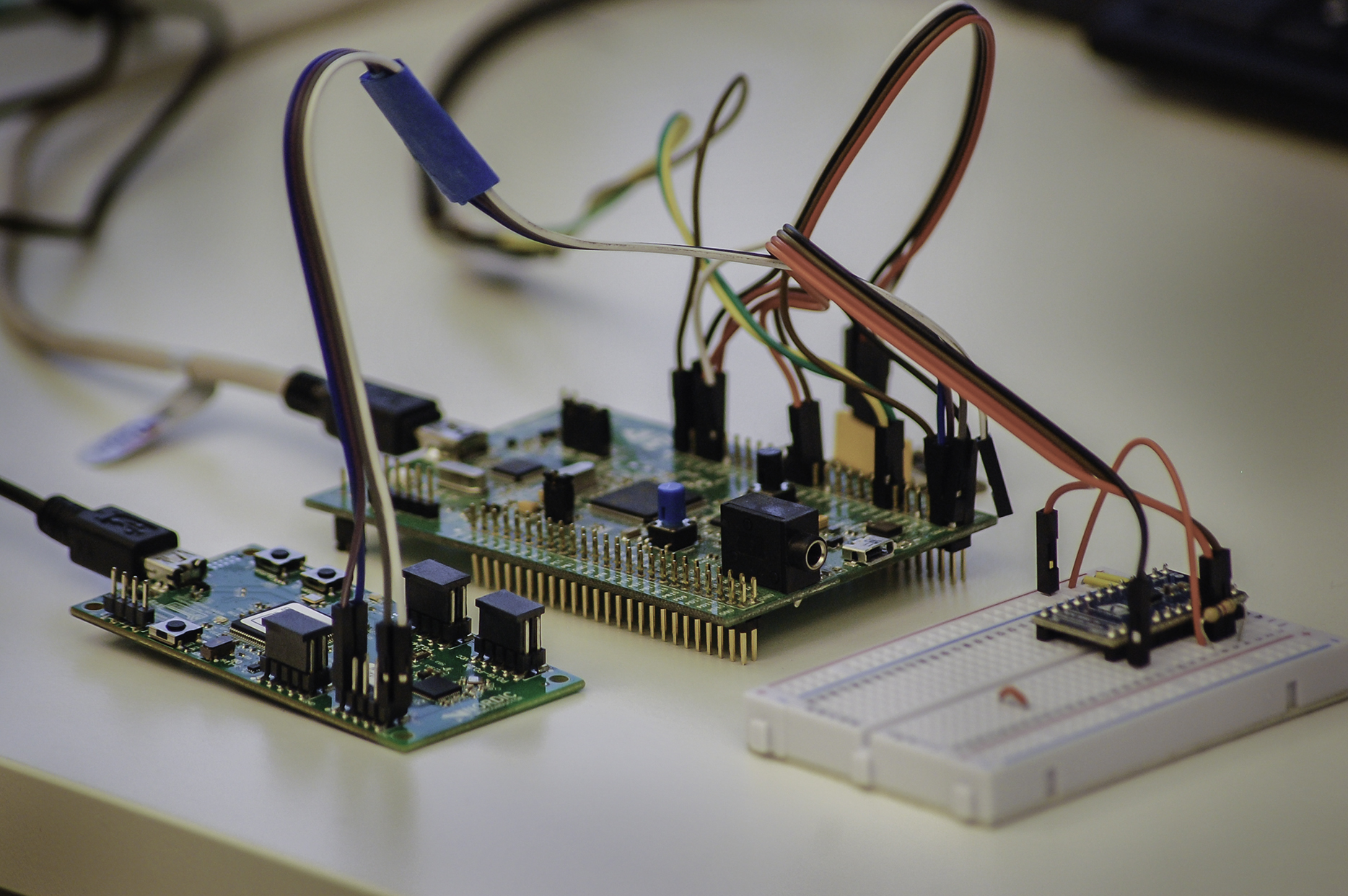
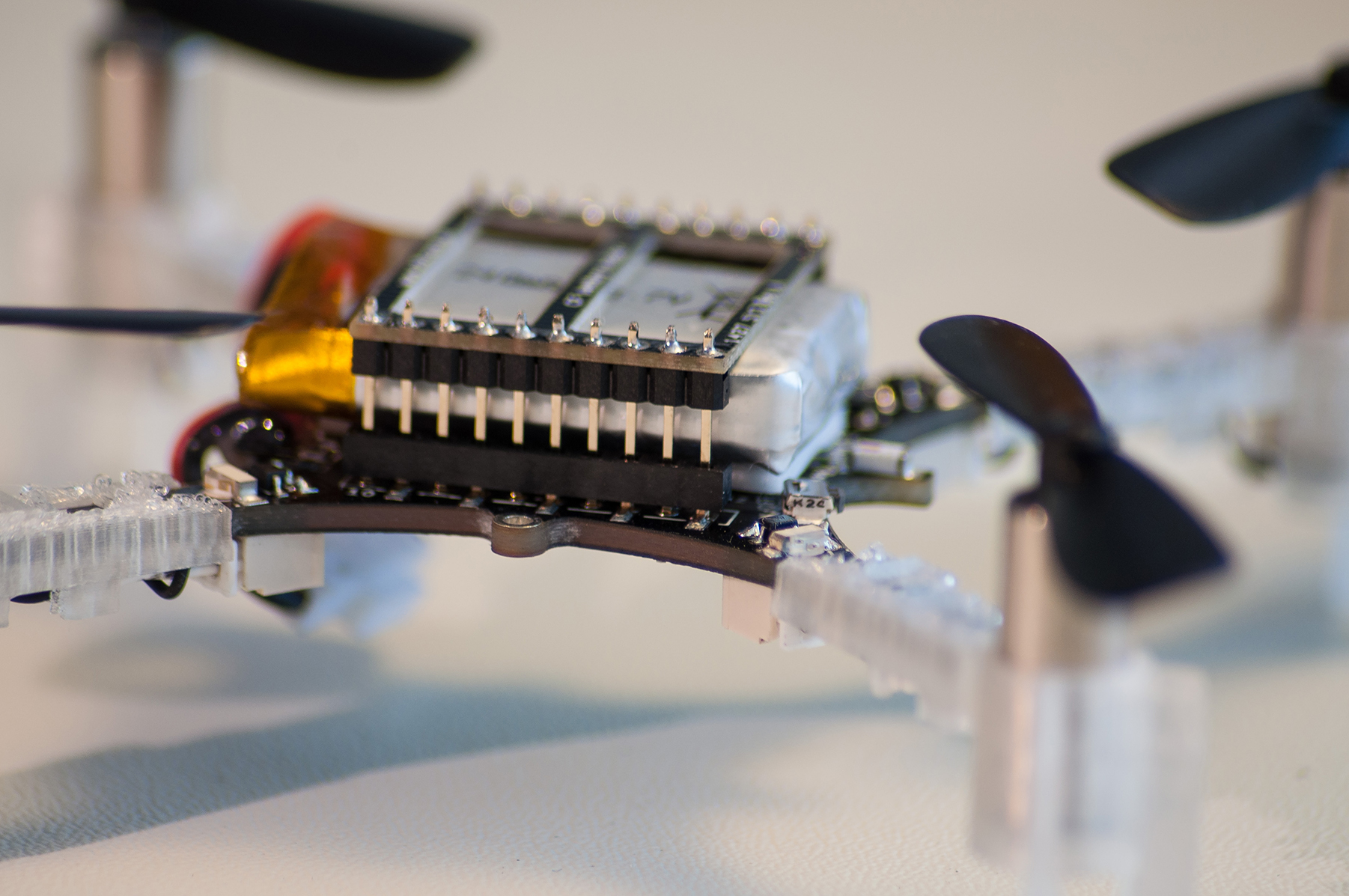
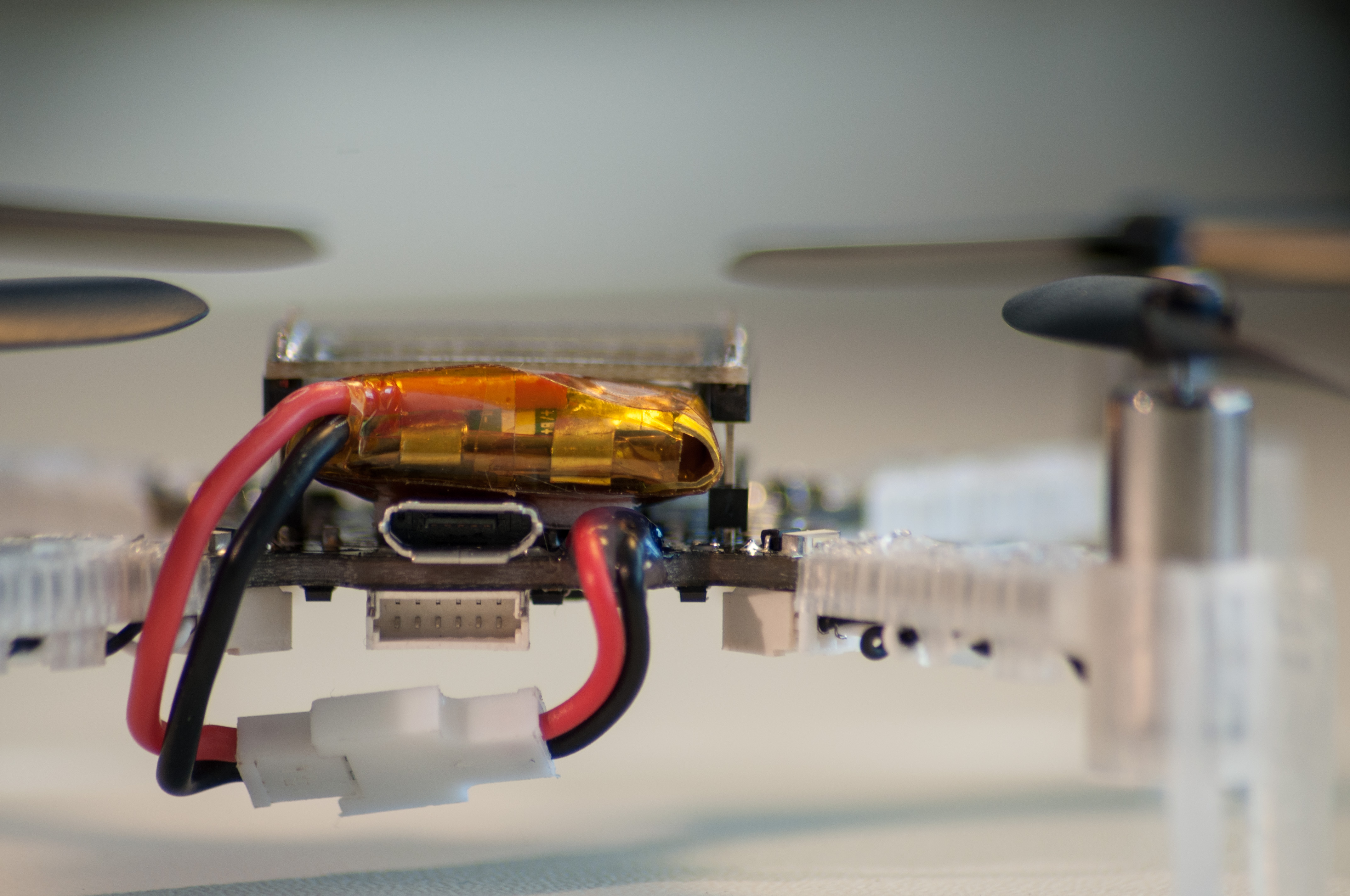
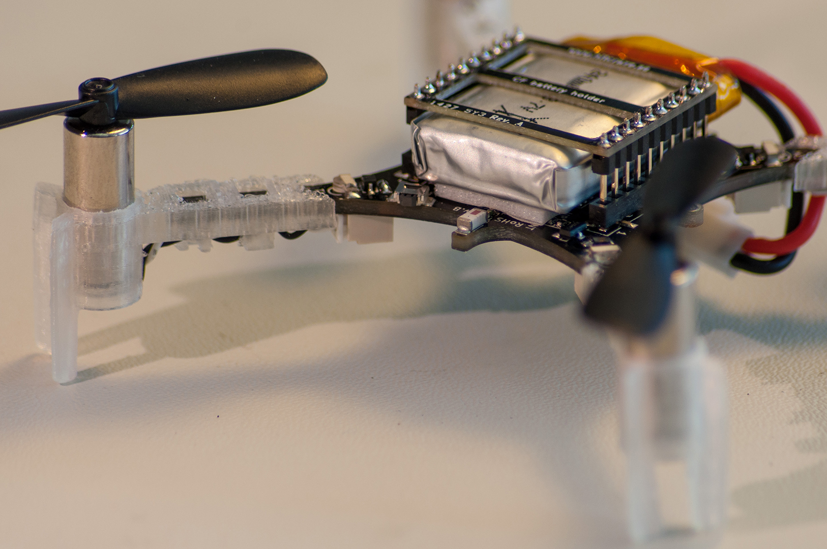
After months of searching (it’s pretty hard finding connectors…) we finally found a solutions that fulfilled all of our requirements. The connectors we found allows users to place multiple boards on the Crazyflie, both on the top and the bottom, and without pre-defined vertical spacing. We only place female connectors on the expansion boards, which means that if you crash and bend the male pins, you just have to exchange them and not any expansion boards. Below are some images showing the expansion connector, the pins and some examples on how you can connect boards. It also shows two of the expansion boards that we have designed, a prototype board and a breakout board for breadboards. In the images we use the breadboard and the breakout board to connect to a pressure sensor from ST and the prototype board to build a flying traffic light :-) The idea of the pattern for the prototype board is taken from ElecFreaks. It allows for easily using both though-hole components and SMD components.
All the boards and the Crazyflie 2.0 with the 3D printed motor mounts are still just prototypes.
Detecting boards
We think that being able to attach different boards is great, but how do we use them in the firmware/software? Well, there are two different use-cases for that. The first one is “pre-made” boards. Aside from the two boards above (prototype and breakout) we have a bunch of ideas and also a few working prototypes that we will write a bit more about later. Let’s use the GPS-expansion that we are working on as an example. When you attach this board you want extra functionality to be available without re-compiling and configuring things. You still want the possibility to hack around in the firmware/software, but you want the hardware to be initialized properly so you don’t have to worry about that. To accomplish this we needed some way to identify the different boards. Again, this needed to be done is a cost-efficient way and without using up too many of the pins in the expansion port. The solution we found is 1-wire memories. So what’s so great about them? Well, they have some nifty features. First of all each produced IC has an unique address, so placing multiple memories on the same buss is no issue. Using a search algorithm you are able to find and identify all the connected memories so that you can address them individually. Secondly they only use, like the name suggest, one wire for communication. This wire is also used for parasitically powering the memory. That means all you need to connect is the one wire and ground. Last, but not least, they are fairly small. The ones we use are in a SOT23 package.
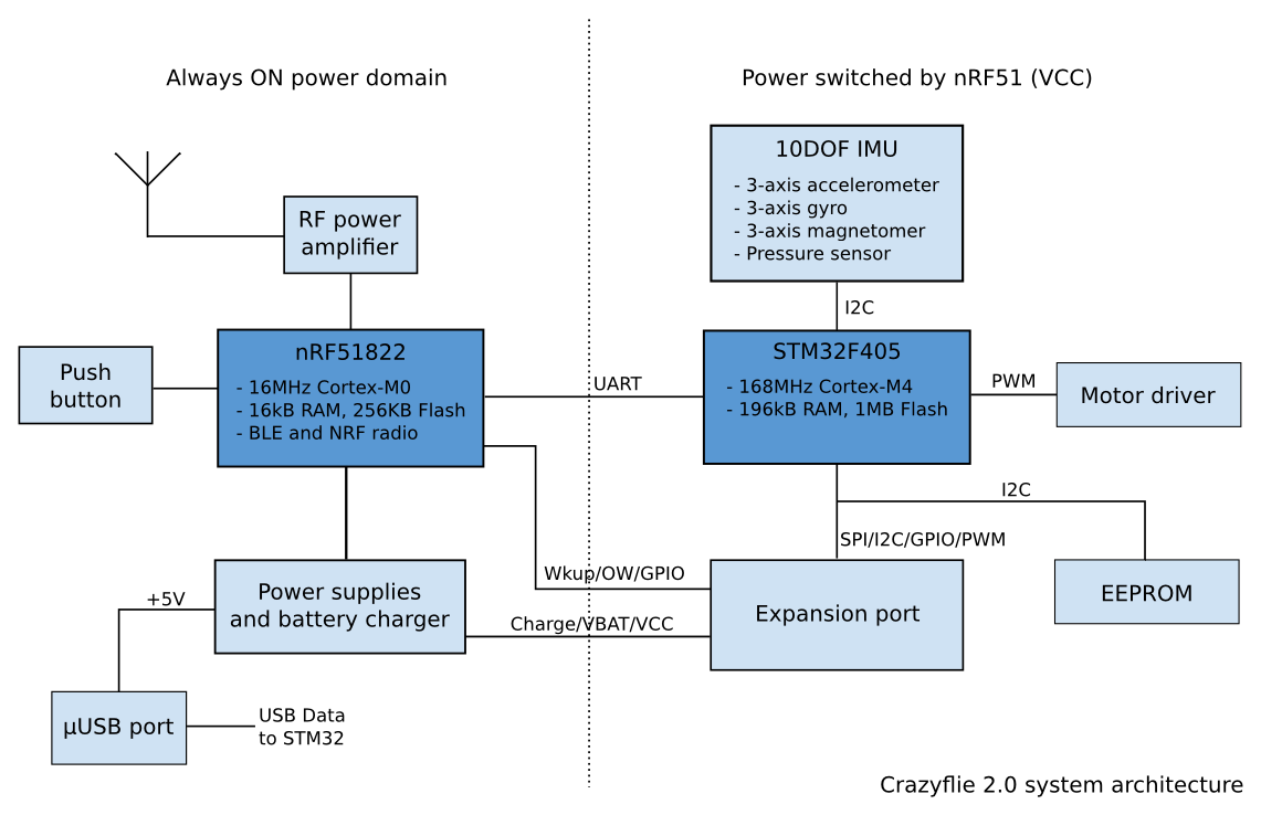
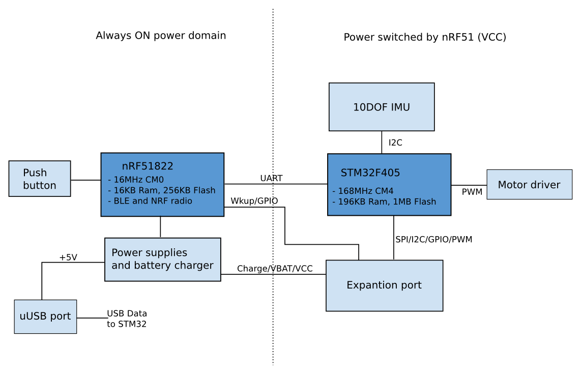
So how are we using these memories? We are placing a memory on every board we design (except for boards like the prototype and breakout boards). The memory is very small, but it’s enough to contain some information about the board. So during production each memory will be programmed with things like what board it is, which revision and what resources (i.e what pins in the expansion port) the board uses. At start-up the 1-wire bus will be scanned and all the memories will be read to detect what boards are attached. Why store what pins the expansion boards use? Well, the nice thing is that the 1-wire bus is connected to the nRF51 (here’s some info on the system architecture). Since the nRF51 is responsible for power management (i.e switching on power for the STM32F4) it’s possible to scan all the memories and detect conflicts in resources before powering on the main system and the expansion boards. Let’s say you attach two boards that use the same UART. This will result in issues when the systems starts running. To protect against this the nRF51 will check if there are any conflicts and won’t power on the system if there is.
The second use-case for expansion boards are the ones you make yourself. Then you might not be interested in using the 1-wire to detect your board. Therefore it’s in no way mandatory to use that feature, it’s just something that we think will make working with our platform easier for our users. But in case you are interested in detecting your own boards, the firmware will support programming the memory and we will link to the correct parts at suppliers.
The pinout of the expansion port
The expansion connector consists of 2 rows of 10 pins each with the spacing of 2mm and has the following pinout:
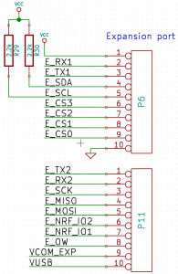
Crazyflie 2.0 expansion port
P6
- VCC – 3V0 regulated supply (max ~50 mA consumption). Only powered when the STM32F4 is powered.
- STM32F4 UART 1 (RX/TX)
- STM32F4 I2C bus (400kHz)
- STM32F4 4xGPIO (can be used as chip select for SPI)
- GND – platform signal ground
P7
- STM32F4 UART 2 (RX/TX)
- STM32F4 SPI (SCK, MISO, MOSI)
- nRF51 2xGPIO that could be used for GPIO but will have the following reserved:
- nRF51 wakeup – allows waking up from an expansion board
- nRF51 external power indication – will indicate if an expansion board is powering the system or not
- nRF51 1-wire memory access
- VCOM – unregulated direct access to power after charger (max 1 A consumption). The voltage is VUSB if a charger is connected and VBAT otherwise. Currently this power supply is always on (even when the system is powered off) witch allow for making always-on expansion board. However we are looking at inserting a high-side switch which would allow also switching this supply off if needed, making prototyping and design of expansion boards a bit simpler.
- VUSB – unregulated direct access to uUSB power. This can either be used to get uUSB power or to supply uUSB power to the platform (like an external charging board that powers and charges the system).
The pins that are connected to the STM32F4 can be used as GPIO or for other functionality that they are multiplexed with, like timers.
Making expansion boards
As many of you probably know, we strive after using open source tool for our development. So for electronics design we use KiCad, an open source EDA suite that works on Linux/Windows/Mac. To make it easier for users to design and make their own expansion boards we have created a template for the design. It contains the initial schematics as well as layout. The connectors are added in the correct positions and the memory is also in. To make things even easier, the layout contains drawings of the Crazyflie 2.0 board outline and connectors, to easily see how the board will fit. As with everything else this needs some cleanup when the final design is in place, but then it will be released under the CC-BY-SA 4.0 license. Looping back to the 1-wire memories, if you make your own board will it be possible to get in on the automatic detection? Sure, the more the merrier. But we still haven’t specified exactly how this will work technically, so we will have to get back on the specifics. If you are interested in hacking something together a great way to go is first to try out the design on a breadboard, then solder it together on the prototype board and finally do the layout in KiCad and order it at a batch-PCB service.


 During the initial design of the new Crazyflie we tried coming up with different use-cases for the new platform. We are not designing a “end-user” product that is intended for a specific end-use, instead we are designing a platform that is aimed at giving us and other users as much flexibility as possible to define the end-use themselves. But we still needed something to aim for, to try out our design on, and see if it could be done. One of these use-cases ended up being a flying sensor node. This might seem like a very specific usage, but we thought that if we come up with a design that would fulfill our basic idea and also a few far fetched ideas, then we would have something good. Hopefully this will be the case :-)
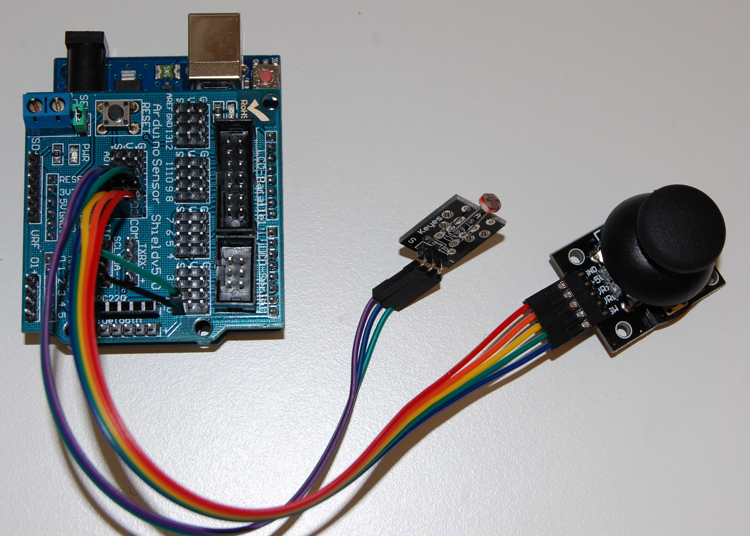