This week’s Monday post is a guest post written by members of the Computer Science and Artificial Intelligence Lab at MIT.
One of the focuses of the Distributed Robotics Lab, which is run by Daniela Rus and is part of the Computer Science and Artificial Intelligence Lab at MIT, is to study the coordination of multiple robots. Our lab has tested a diverse array of robots, from jumping cubes to Kuka youBots to quadcopters. In one of our recent projects, presented at ICRA 2017, Multi-robot Path Planning for a Swarm of Robots that Can Both Fly and Drive, we tested collision-free path planning for flying-and-driving robots in a small town.
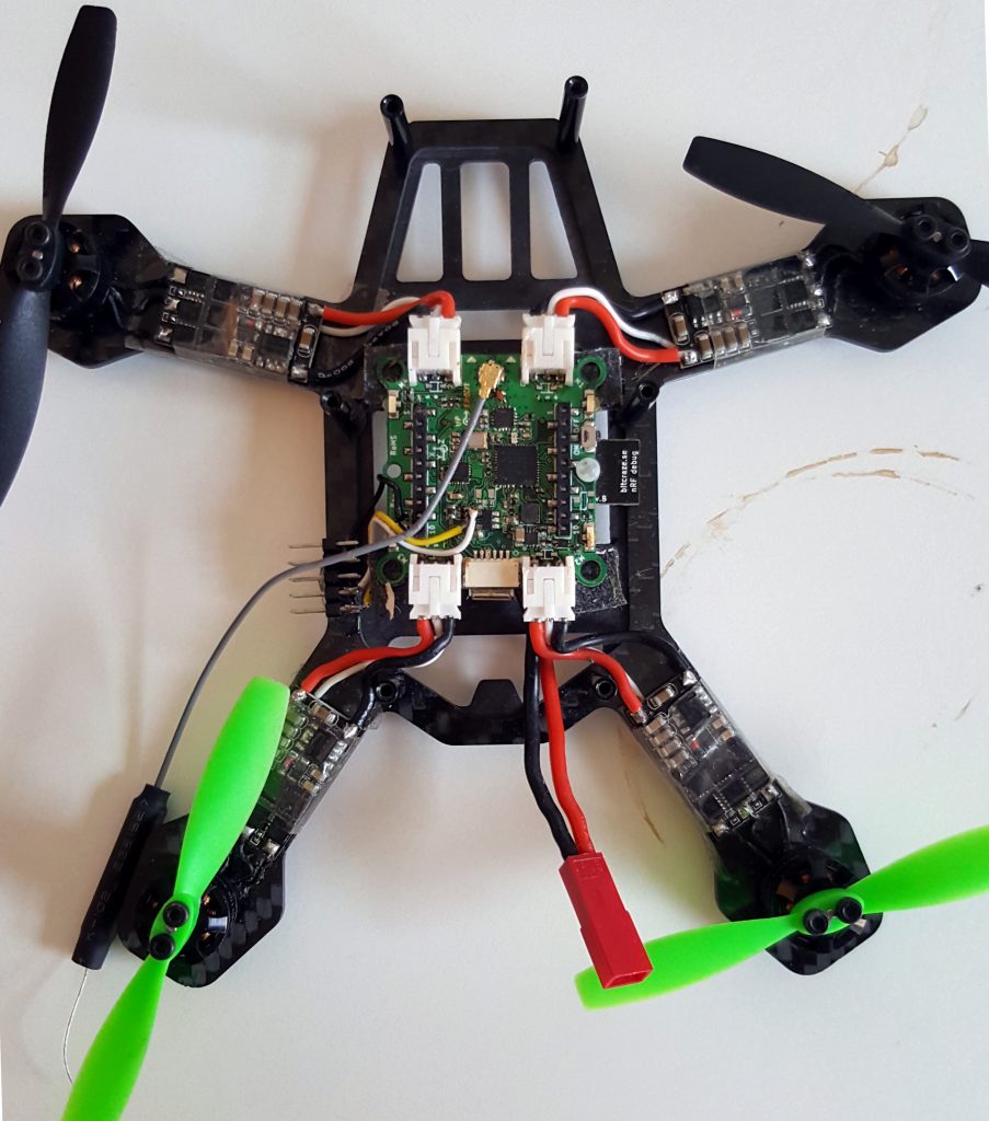
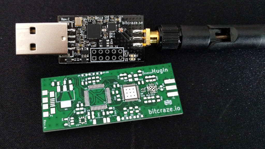
Robots that can both fly and drive – in particular wheeled drones – are actually somewhat of a rarity in robotics research. Although there are several interesting examples in the literature, most of them involve creative ways of repurposing the wings or propellers of a flying robot to get it to move on the ground. Since we wanted to test multi-robot algorithms, we needed a robot that would be robust, safe, and easy to control – not necessarily advanced or clever. We decided to put an independent driving mechanism on the bottom of a quadcopter, and it turns out that the Crazyflie 2.0 was the perfect platform for us. The Crazyflie is easily obtainable, safe, and (we can certify ourselves) very robust. Moreover, since it is open-source and fully programmable, we were able to easily modify the Crazyflie to fit our needs. Our final design with the wheel deck is shown below.
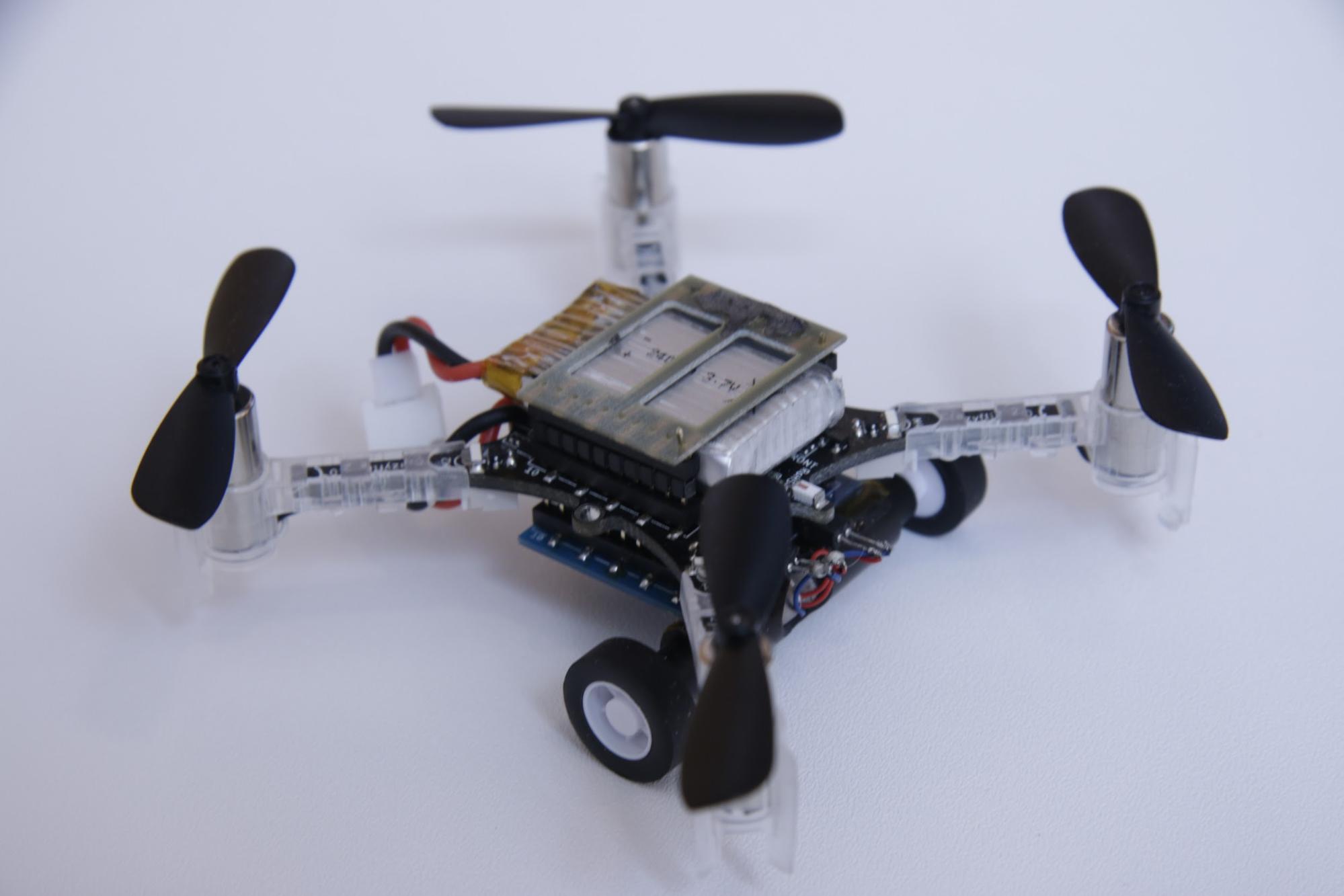
A photo of the Crazyflie 2.0 with the wheel deck.
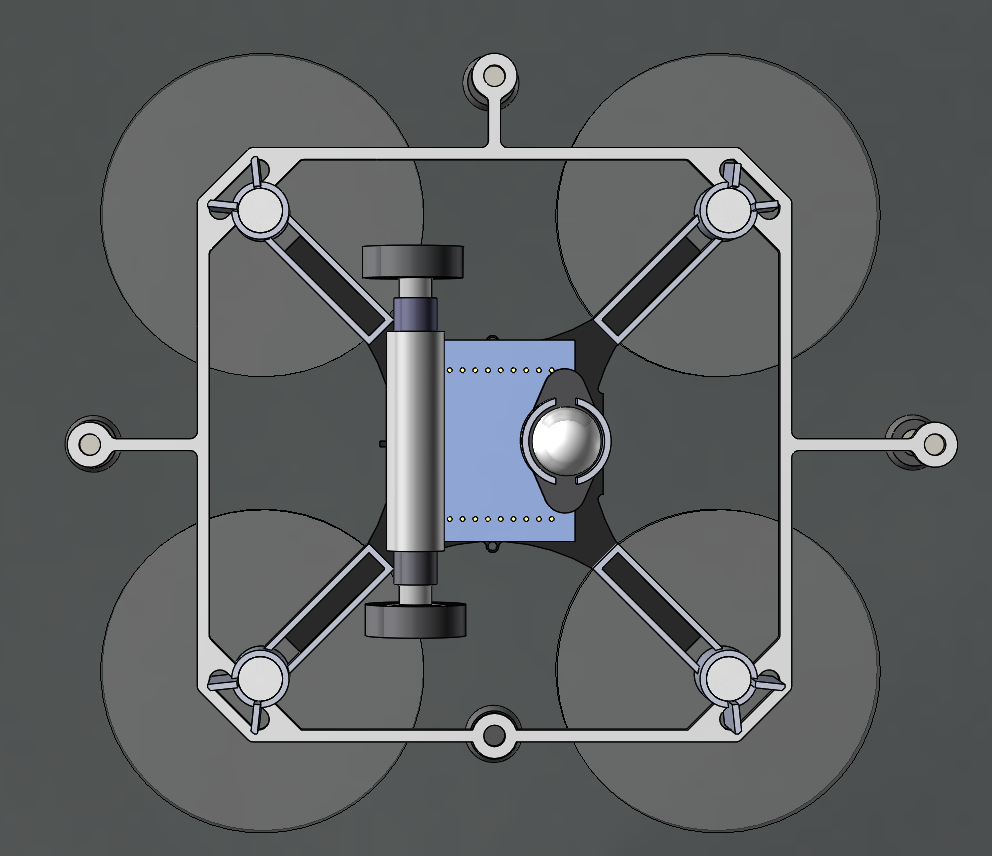
A model of the Crazyflie 2.0 with the wheel deck from the bottom
The wheel deck consists of a PCB with a motor driver; two small motors mounted in a carbon fiber tube epoxied onto the PCB; and a passive ball caster in the back. We were able to interface our PCB with the pins on the Crazyflie so that we could use the Crazyflie to control the motors (the code is available at https://github.com/braraki/crazyflie-firmware). We added new parameters to the Crazyflie to control wheel speed, which, in retrospect, was not a good decision, since we found that it was difficult to update the parameters at a high enough rate to control the wheels well. We should have used the Crazyflie RealTime Protocol (CRTP) to send custom data packages to the Crazyflie, but that will have to be a project for another day.
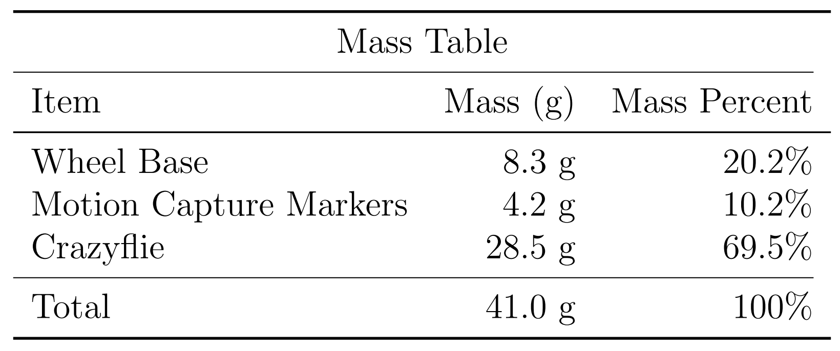
The table below shows the mass balance of our miniature ‘flying car.’ The wheels added 8.3g and the motion capture markers (we used a Vicon system to track the quads) added 4.2g. So overall the Crazyflie was able to carry 12.5g, or ~44% of its body weight, and still fly pretty well.
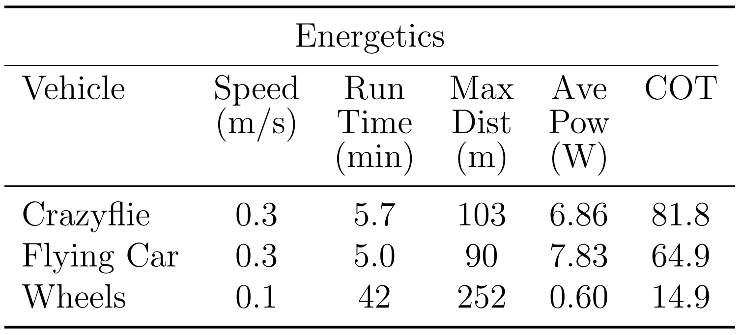
Next we measured the power consumption of the Crazyflie and the ‘Flying Car.’ As you can see in the graph below, the additional mass of the wheels reduced total flight time from 5.7 minutes to 5.0 minutes, a 42-second or 12.3% reduction.
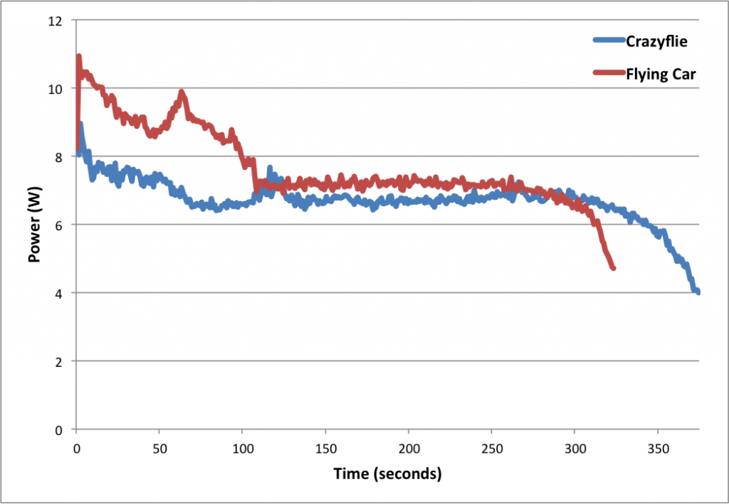
Power consumption of the Crazyflie vs. the ‘Flying Car’
The table below shows more comparisons between flying without wheels, flying with wheels, and driving. The main takeaways are that driving is much more efficient than flying (in the case of quadcopter flight) and that adding wheels to the Crazyflie does not actually reduce flying performance very much (and in fact increases efficiency when measured using the ‘cost of transport’ metric, which factors in mass). These facts were very important for our planning algorithms, since the tradeoff between energy and speed is the main factor in deciding when to fly (fast but energy-inefficient) versus drive (slow but energy-efficient).
Controlling 8 Crazyflies at once was a challenge. The great work by the USC ACT Lab (J. A. Preiss, W. Hönig, G. S. Sukhatme, and N. Ayanian. “Crazyswarm: A Large Nano-Quadcopter Swarm,” ICRA 2017. https://github.com/USC-ACTLab/crazyswarm) has made our minor effort in this field obsolete, but I will describe our work briefly. We used the crazyflie_ros package, maintained by Wolfgang Hönig from the USC ACT Lab, to interface with the Crazyflies. Unfortunately, we found that a single Crazyradio could communicate with only 2 Crazyflies at a time using our methods, so we had to use 4 Crazyradios, and we had to make a ROS node that switched between the 4 radios rapidly to send commands. It was not ideal at all – moreover, we had to design 8 unique Vicon marker configurations, which was a challenge given the small size of the Crazyflies. In the end, we got our system to work, but the new Crazyswarm framework from the ACT Lab should enable much more impressive demos in the future (as has already been done in their ICRA paper and by the Robust Adaptive Systems Lab at Carnegie Mellon, which they described in their blog post here).
We used two controllers, an air and a ground controller. The ground controller was a simple pure pursuit controller that followed waypoints on ground paths. The differentially steered driving mechanism made ground control blissfully simple. The main challenge we faced was maximizing the rate at which we could send commands to the wheels via the parameter framework. For aerial control, we used simple PID controllers to make the quads follow waypoints. Although the wheel deck shifted the center of mass of the Crazyflie, giving it a tendency to slowly spin in midair, overall the system worked well given its simplicity.
Once we had the design and control of the flying cars figured out, we were able to test our path planning algorithms on them. You can see in the video below that our vehicles were able to faithfully follow the simulation and that they transitioned from flying to driving when necessary.
Our work had two goals. One was to show that multi-robot path planning algorithms can be adapted to work for vehicles that can both fly and drive to minimize energy consumption and time. The second goal was to showcase the utility of flying-and-driving vehicles. We were able to achieve these goals in our paper thanks in part to the ease of use and versatility of the Crazyflie 2.0.