We already wrote in a previous blog post that we where working on a Lighthouse positioning receiver deck for the Crazyflie 2.0. In this post we will describe a bit what has been the development process so far for this deck as it is an example of how to develop with the Crazyflie. Basically, our way of working often is to try to get one things working after another, this is what we have done here: we start from a hack and then we replace hardware and software pieces one after the other to make sure we always have one half (hardware of software) we can relie on.
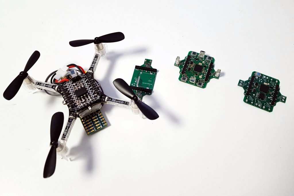
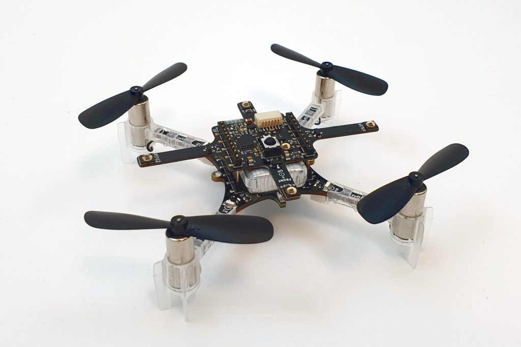
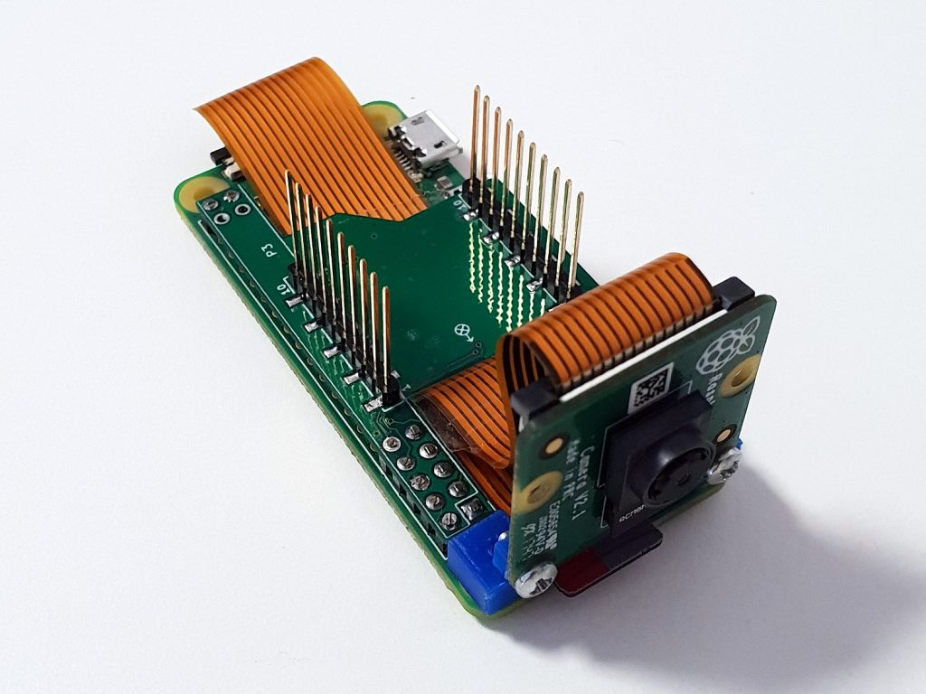
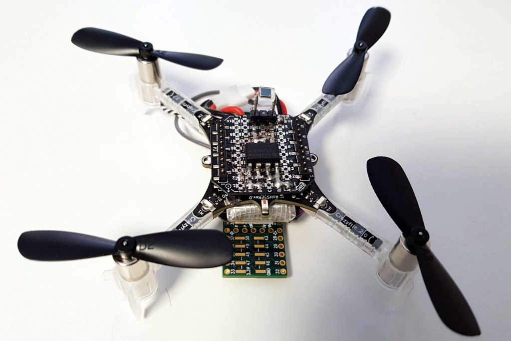
The lighthouse deck started as a Fun Friday project, and as such we usually want to hack something together to see if the idea can work. So I looked around the web to get some information as of how to receive the lighthouse positioning signals and decode it. I found the vive-diy-position-sensor GitHub project by ashtuchkin. The project describe the schematic and contains the software for a Teensy board to receive a lighthouse 1.0 signal and calculate the position of the receiver. I went forward and cabled the circuit on a Crazyflie prototyping deck and attached a Teensy board to another prototyping deck. The idea is to install these two board above and bellow a Crazyflie:
Discreet-component Lighthouse receiver
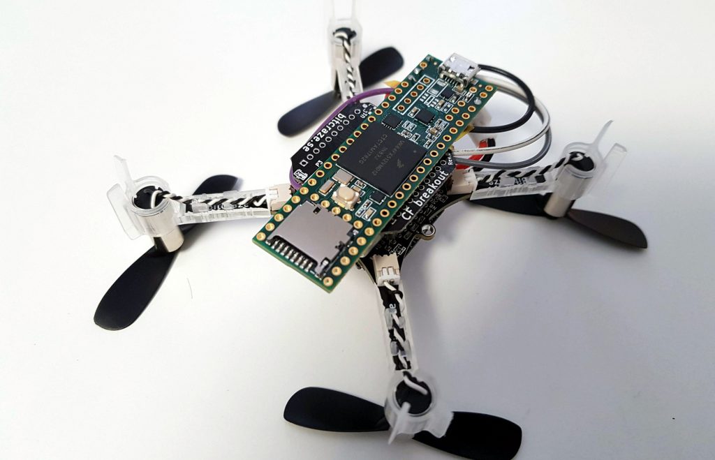
Teensy to decode the lighthouse signals
The signal from the lighthouse receiver goes to the Teensy, then the serial port of the Teensy is connected to the serial port of the Crazyflie. As a first approach the Teensy was configured and we could get the position data using the Teensy USB port. When everything was working correctly I could implement a small deck driver in the Crazyflie to receive the position and push it in the Kalman filter. This way I could get a Crazyflie 2.0 flying in lighthouse with minimal firmware work.
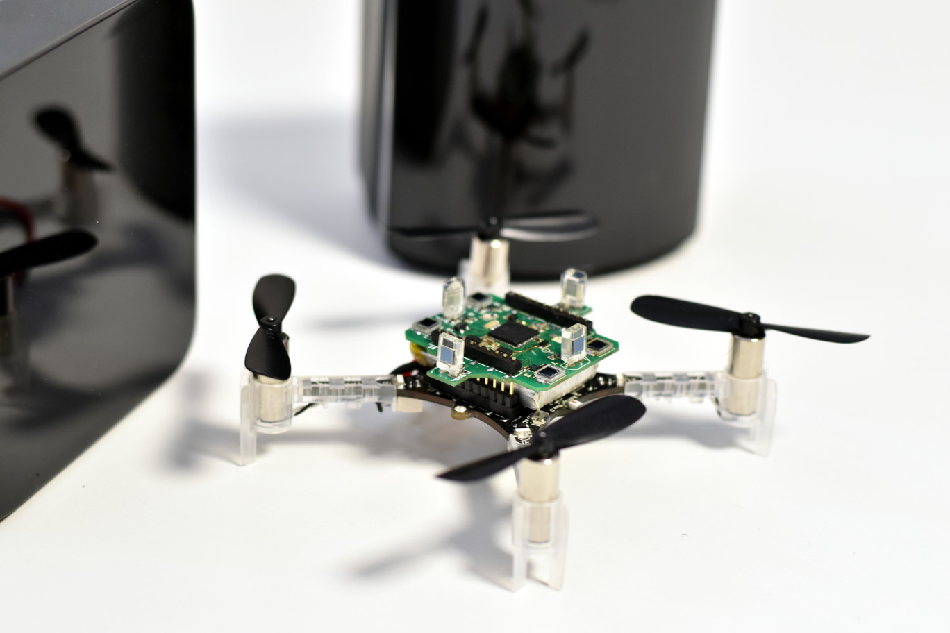
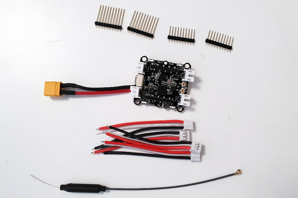
The obvious next step was to get rid of the Teensy, this was done by implementing the lighthouse pulse acquisition and interpretation in the Crazyflie. Once that was done, we could make our own deck. Instead of using op-amp we used the official receiving chip available at this time, the TS3633:
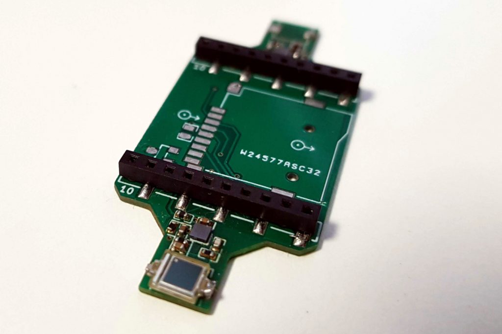
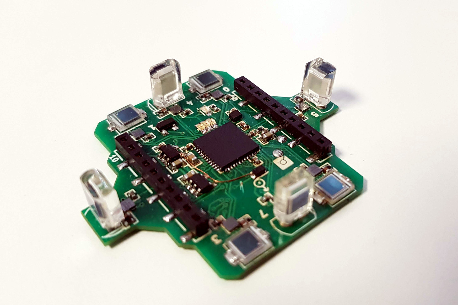
First lighthouse receiving deck prototype
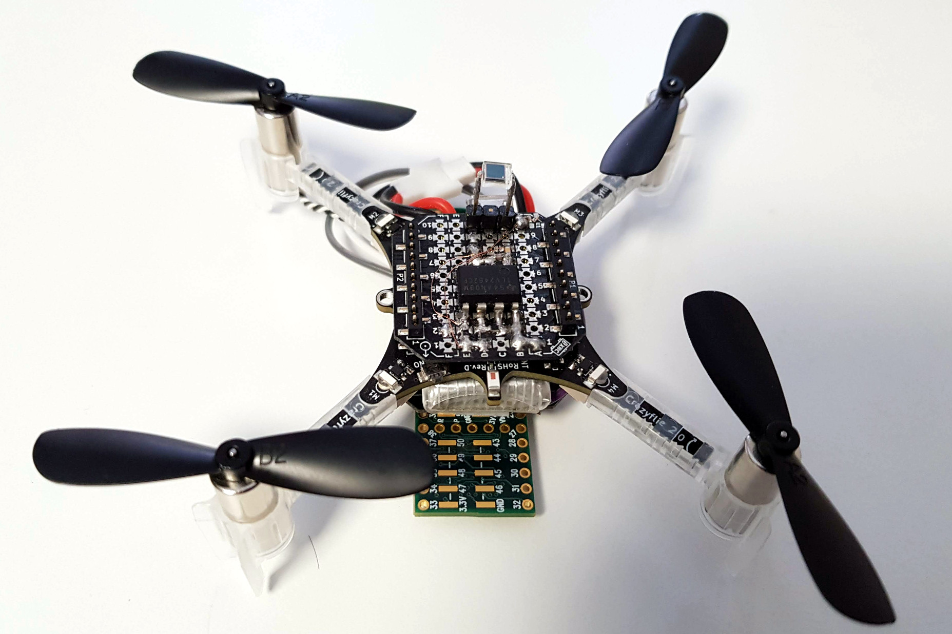
This board implements up to two receiver which would allow to get the orientation as well as the Position of Crazyflie. Due to questionable soldering only one receiver has ever worked but the prototype was useful to test the concept anyway, one of the lesson learned is that the receiving angle of the two flat is not big enough to fly very high, with the two lighthouse base station near the ceiling we could only fly up to ~1.5m before loosing the signal. We would need a microcontroller or other chip capable of acquiring the signals on the deck since the Crazyflie 2.0 deck port only has two input capable of acquiring the pulses.
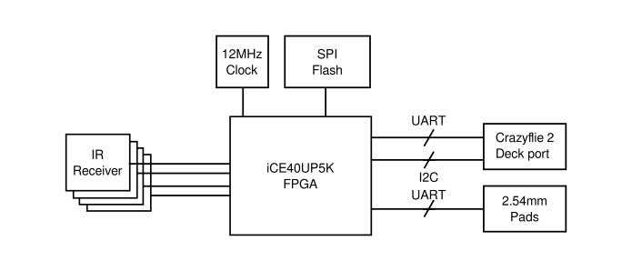
At this point informations about Lighthouse 2.0, the next version of Lighthouse tracking that will allow to cover much bigger area, started appearing on the internet and a new receiver chip was release to receive the signal, the TS4231. One big difference was that Lighthouse 2.0 would transmit data in the laser carrier. The data transmitted are in the range of 1 to 10MHz dixit the TS4231 datasheet so it makes them impractical to acquire with a microcontroller. This gives us a perfect opportunity to play with the iCE40 FPGA and the icestorm open-source toolchain that has just been release.
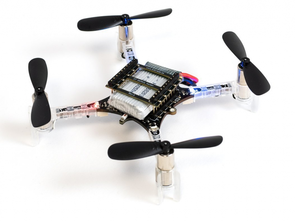
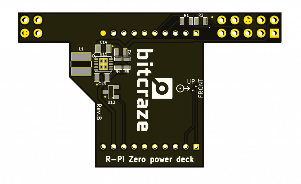
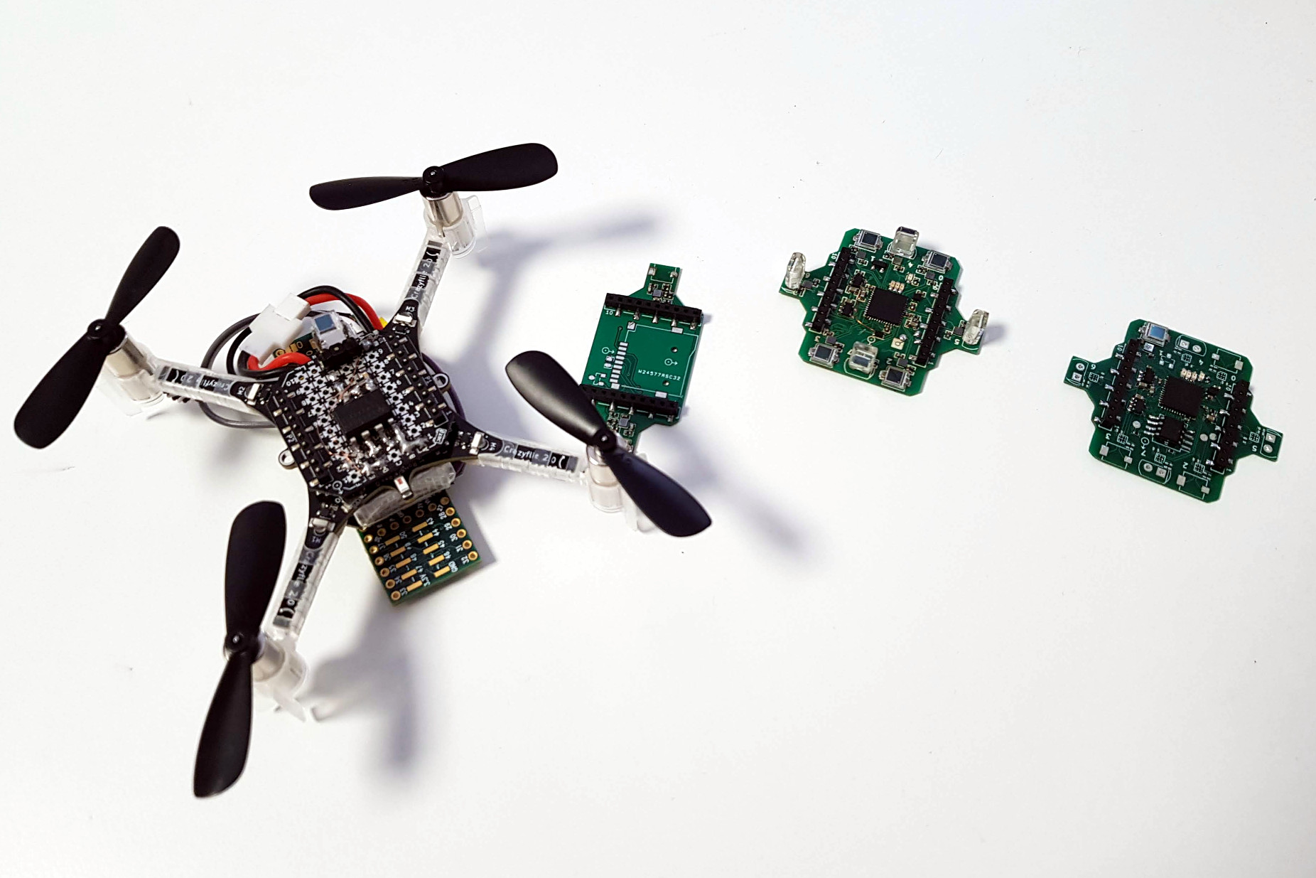
The result is a deck containing enough receiver to cover a much bigger flying space and an iCE40UP5K FPGA to acquire the signals sent by the lighthouse. There is already two prototype of this design: one without SPI flash, so the Crazyflie would have to embed the FPGA configuration bitstream and program it at startup and the latest one has an SPI flash so the deck can start by itself:
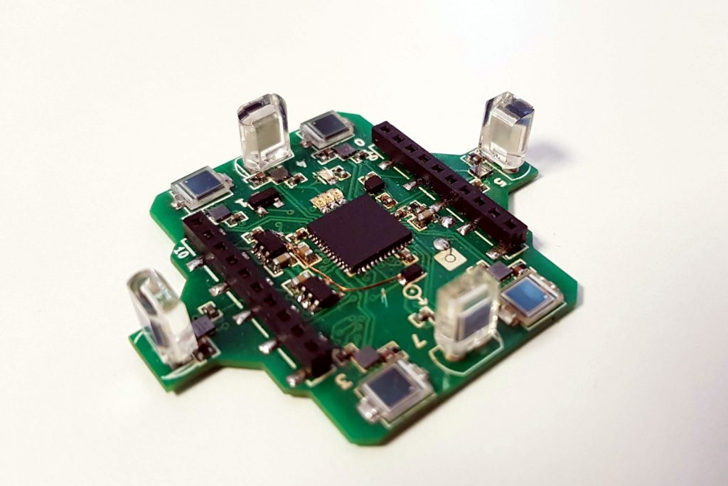
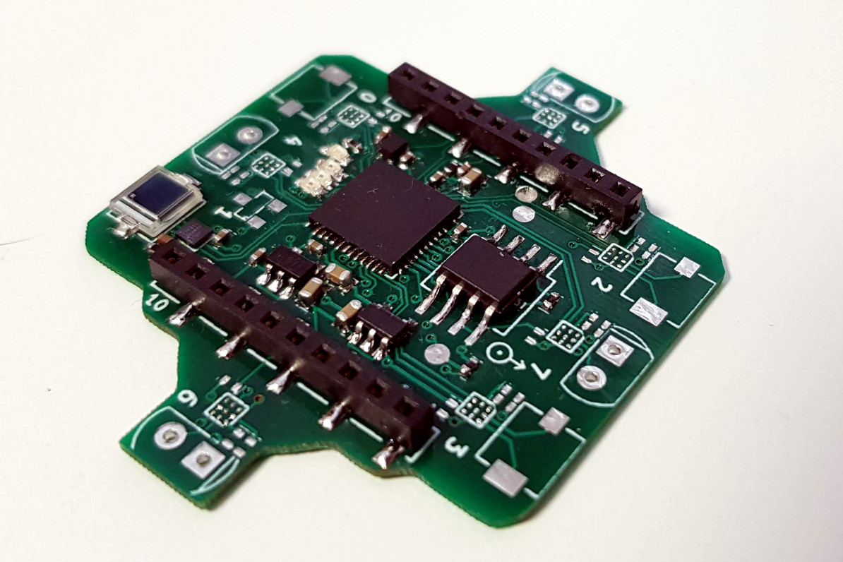
First FPGA-Based lighthouse deck prototype
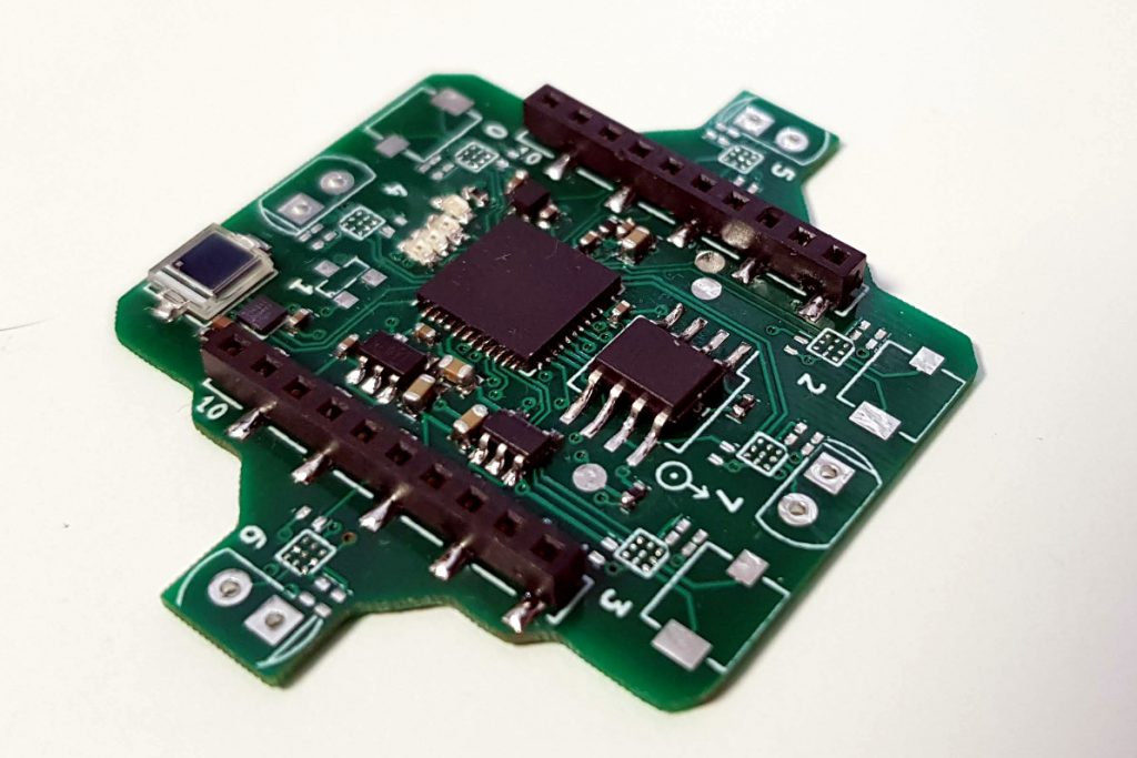
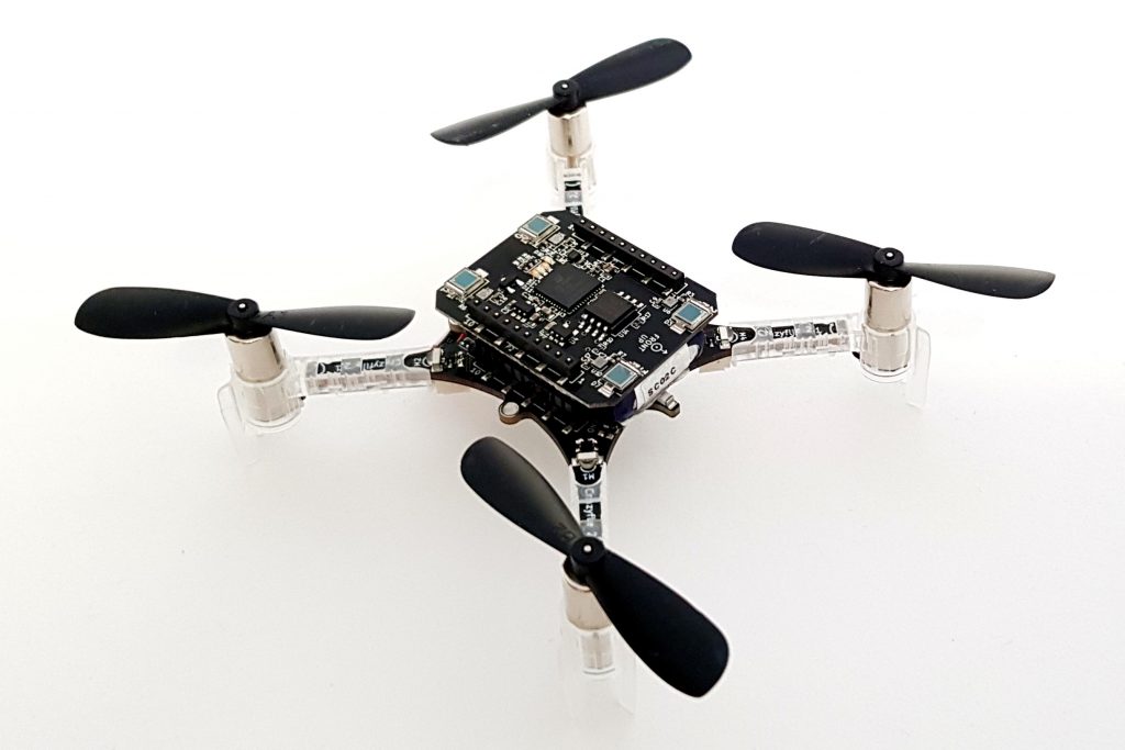
Partially populated second FPGA-Based lighthouse deck prototype, now with SPI flash
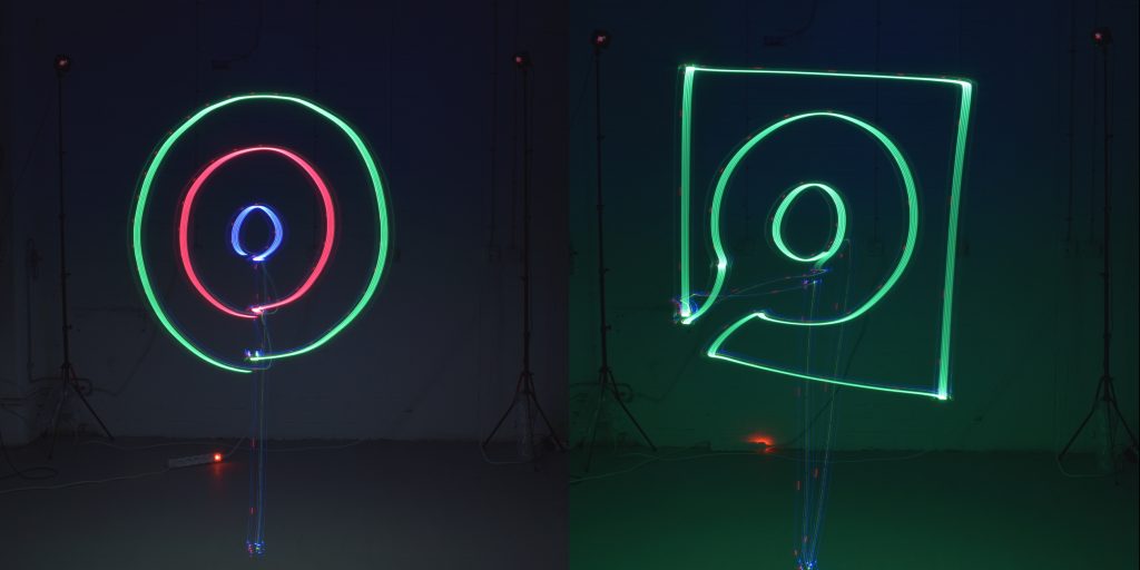
As a first approach the FPGA will acquire the Lighthouse 1 pulses and send the raw timing via a serial port to the Crazyflie. The Crazyflie can then decode and interpret the pulse. I am currently playing with the idea of maybe running a picorv32 Risc-V 32 bits CPU core in the deck, this will allow to acquire and interpret the pulses in the deck and send angles to the Crazyflie, this would greatly lighten the processing load on the Crazyflie 2.0. Eventually this FPGA should be able to acquire and decode the Lighthouse 2.0 signals.
This is very much work in progress and we will write more about the Lighthouse deck when we have further results.