As many out there think is is more fun to fly the Crazyflie rather then develop upon it (like we do :-)) we have quickly looked at ways to pilot it with a RC transmitter. This forum thread is a good starting point for a developer discussion. To summarize it a bit there are many ways of implementing it which all require more or less development and has different pros/cons
- Attach the Crazyradio PA to the expansion module/port of an RC transmitter.
- Implement the E-Sky transmitter protocol or other nRF24L01+ protocols in the nRF51.
- Using the DeviationTx code and a nRF24L01+ module.
- Attaching a RC receiver to the deck (expansion port) interface.
Today I will write a bit more about the DeviationTx as it is a great open source project and that it has support for the Crazyflie. It was over a year ago we got contacted by Victor who wanted to implement the Crazyflie protocol in the DeviationTx code base, which he did pretty quickly. We feel ashamed for taking so long to try it out. So during the weekend I freed up some time and gave it a shot. The DeviationTx project replaces the firmware in Walkera transmitters with a better one which has the possibility to support a great amount of RC models. However many of them use different transceivers modules so this must be added to the hardware. Well a bit of hardware hacking is always fun and we had a nRF24L01+PA module laying around. They have a module installation document but I found it easier follow this guide as I had the same type of module and transmitter (Devo7e).
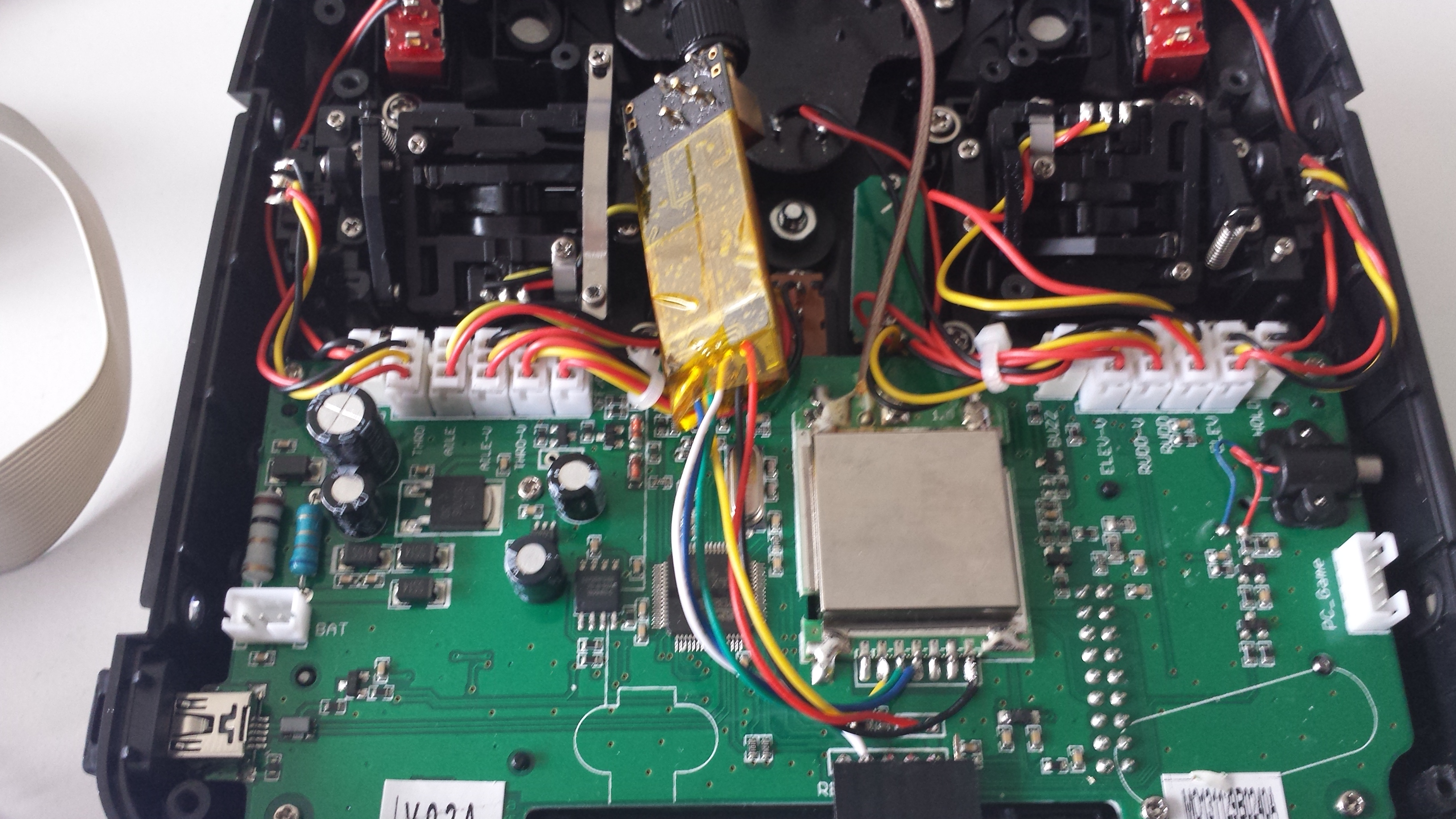
The module installation was done pretty quickly but what took time was to update the firmware. The instructions tells one to download the walkera update tool but I just couldn’t find it on their website, nor the original walkera devo7e firmware (which they recommend to test with first). Thankfully I could find one using google and ended up using this link. Next thing was to fire up a windows 7 virtual machine to install it in which it worked without problems. So did the flashing of the DeviationTx firmware, I flashed the nightly build 4.0.1 and copying the file system according to the instructions. What I forgot though was to edit the hardware.ini file to enable the module which I understood when the protocol selection had a star in front of the name <*CFlie> (OK, I admit, I thought the hardware wasn’t working at first…). Then I setup a new model using the <CFlie> and I used the Fixed ID to setup the address, The data rate and channel are combined in the fixed id using channel as lowest two decimal digits and the rate the first were 0, 1, and 2 for 250kbit/s, 1Mbit/s, and 2Mbit/s respectively. So channel 80 on 2Mbit/s is encoded as 280 and channel 80 on 250kbit/s as 80.
And boy I was happy when I saw the green led (radio com led) blink on the Crazyflie 2.0, but nothing happened when I pushed the trust… Then I remembered, we recently implemented a lock so that a zero thrust must be sent at least once for it to unlock (to prevent Crazyflie to fly away if the gamepad is not setup correctly and constantly sends 100% thrust :). Looking into the source code one could see the trust was at minimum 5535 which was never unlocking the thrust. Removing this lock in the Crayflie 2.0 firmware and it was flying! but in plus mode… The Deviation cflie module code seem to rotate the pitch/roll setpoints.
Next step will be to do some modifications to the Deviation cflie module for Crazyflie 2.0, adding code to unlock the thrust and disabling the axis rotation, then make a pull request to the DeviationTx project for everyone to enjoy.
A big thanks to the DeviationTx project and to Victor for the cflie module implementation! Ohh, and by the way, they are making a universialTx module that will support almost any RC model out there, including Crazyflie, can’t wait to see that.