Category: Crazyflie

Finally here is the last, and probably most interesting part of the “Measuring propeller RPM” series, see part 1 and part 2 to catch up. Now it is time to gather some data and display what we get.

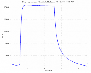
As described in part 2 we are now able to measure each propeller RPM with the expansion board we made and with the code we added. This can, as been described in part 2, be logged to a csv file using the cfclient. Next thing would be to do something useful with it. To do that we use Octave (very similar to Matlab but open source). The first thing that could be interesting to know is the step response for a  motor and propeller. This was acquired by altering the Crazyflie 2.0 firmware a bit to do a step from zero to max trust and then to zero again. It was done on M1 with a fully charged battery.

M1 step response


The motor goes from zero to 25k rpm in about 180ms, quite impressive. What is also interesting is that the falling slope in the range 15k to 20k rpm is quite similar to the rising slope in the same region. The inertia of the turning parts of the motor and the propeller is quite low so this energy will quickly be consumed when the motor and propeller starts to coast. This is good as it will lead to better maneuverability.
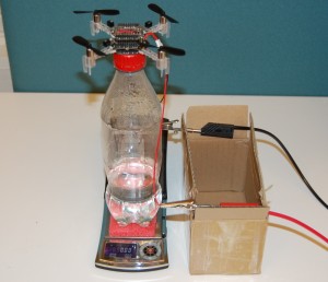


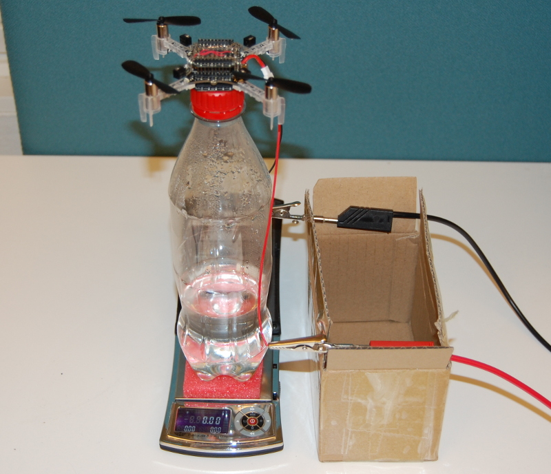
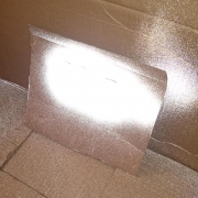
cf2 thrust fixtureKnowing the RPM is great but it is the thrust that is most interesting. So to get this we need a rig where we can measure it. We made one out of a bottle to which we glued a prototype board on that we put on a scale, not a perfect rig but simple and probably good enough. Then we made a program that ramped up the PWM from 0% to 93.75% in 16 steps with stabilization disabled. We also connected the Crazyflie 2.0 to a power box where we could measure the current. The program would increase the thrust in 16 steps and during each step we took a reading of the thrust and current. The RPM, voltage and PWM was logged over the cfclient at the same time. Some manual work was needed afterwards to correlate the data and get it into a table. While in the table a lot of interesting plots could be graphed.
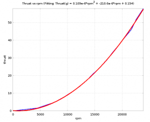
rpm and thrustThe first one would be the rpm and thrust as this transfer function is interesting. By using the Octave polyfit function the second order fit could be found. It is a pretty accurate fit and with this fit it is easier to get the thrust, as the rpm is the only variable needed, which is easier to measure. The fitting function returned by polyfit is:

Thrust (in gram) = 1.0942e-07*rpm² – 2.1059e-04*rpm + 0.15417.


Here is a combined plot of some other interesting parameters. Notice that the voltage graph is ~quadratic, the current ~square-root and the power linear. From the power graph one can find out that the thrust efficiency is about 3.8 gram/W. Not super good but pretty good for a quad of the Crazyflie 2.0 size.

thrust_v_a_w_rpm_tight

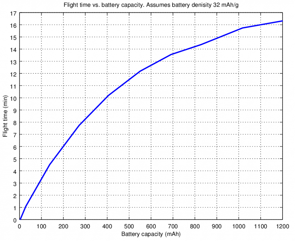
Another interesting graph is the graph of the flight time. Since we know the power consumption and the battery characteristics we can plot a graph of an estimated flight time depending on the battery size. This graph makes the assumption the battery capacity per weight is 32mAh/g.

flighttime_capacity

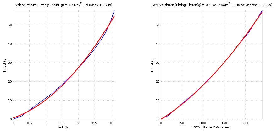
And finally the transfer function we set out to find, the PWM to thrust. The problem with this is that motors are controlled by voltage (PWM) and the voltage comes from the battery, which varies with the power taken from the battery due to internal resistance. Therefor we made two fitting functions, one based on measured battery voltage while applying PWM, and one based on the PWM. Looking at the graph one interesting thing is that the polyfit is making a better fit (red curve) for the PWM. I would have expected the opposite. Something that we will have to investigate further. Or maybe one of our readers have the answer?

pwm_to_thrust

On the wiki we will update this analysis with some more details and the raw data so if you are interested please have a look! Hopefully using this information we can make the Crazyflie 2.0 fly even better.

On the news side there is a new version of the Android client available on Google play, thanks Fred! Also Fred has uploaded the slides of his Crazyflie lightning talk at Fosdem 2015.
We finally got some time to follow up on the previous blog post Measuring propeller RPM: Part 1. In this post we will continue where we left of and describe a little about the software we have implemented.

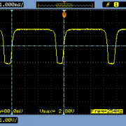
The sensor output, as showed in the scope picture, can be connected directly to a digital input. We connected them to the expansion port signals TX2, RX2, IO2 and IO3 as they are all internally connected to a timer with capture capability, TIM5_CH3, TIM5_CH4, TIM3_CH2, TIM3_CH1 respectively. With the capture functionality it is possible to trigger a timer read on events like a pin change. Thus it is not that difficult to calculate the period time of the input signal which can be used to calculate the rpm. Setting up the timer to run at 1us tick was a bit tricky but manageable. With 1us tick it will wrap around, it’s a 16 bit timer, so after 1us * 65536 = 65.5ms. This means the slowest rpm that can be measured is about 458 rpm (1/(2*65.5ms)*60). The division by 2 is because there are 2 blades on the prop. Since hovering happens way over 458 rpm it doesn’t matter much that we can’t measure any slower speed.

Next thing was to setup the capture compare. The ST library already provides the basic API, TIM_ICInitStructure, so it was more or less just a matter of finding how to configure it. The capture part of the timer can do quite fancy things but in the end we decided it was easiest to just use it the simple way, were it stores the timer value in the corresponding capture compare register on a predefined edge. As the register values will be overwritten when the next pulse comes we setup a interrupt handler to take care of the result. What the interrupt handler ended up to do was to copy the timer value, use that to calculate the rpm and then save the result in a variable. It turned out to be good to do an average of the two latest values as the pulses was not fully symmetrical because of the two blades. This was then done the same way for each propeller input and, voilà, rpm measurements was taken. (Well, there certainly was a bit of hair pulling before it all worked but in the end it worked! Love that feeling)

Getting it down to a cfclient was a piece of cake using the logging framework. We just defined the variables to be logged, setup the logging in the cfclient and it could all be plotted. The variables was defined using the macros below.

LOG_GROUP_START(rpm)
LOG_ADD(LOG_UINT16, m1, &m1rpm)
LOG_ADD(LOG_UINT16, m2, &m2rpm)
LOG_ADD(LOG_UINT16, m3, &m3rpm)
LOG_ADD(LOG_UINT16, m4, &m4rpm)
LOG_GROUP_STOP(rpm)

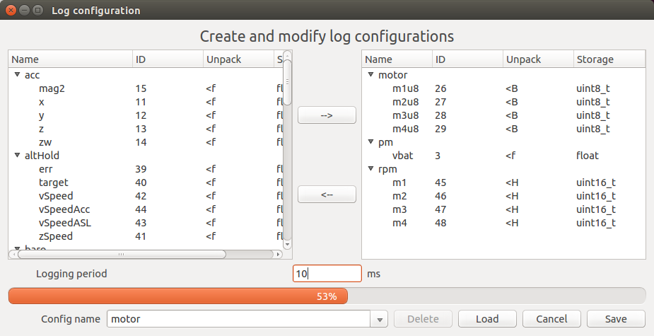
Then by connecting the the Crazyflie a log configuration could be created called “motor” containing the rpm values as well as voltage and PWM.

log configuration rpm

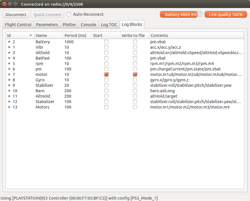
After that by opening the Log Blocks tab the “motor” log configuration could be enabled a written to files. The data log output folder can be opened from the menu by selecting “Settings -> Open config folder”. In my case in “logdata/20150202T17-29-49/motor-20150202T17-35-09.csv”. This CSV file can then be imported to a program such as Octave, Matlab, Spreadsheet etc for further analysis.

Log write to file

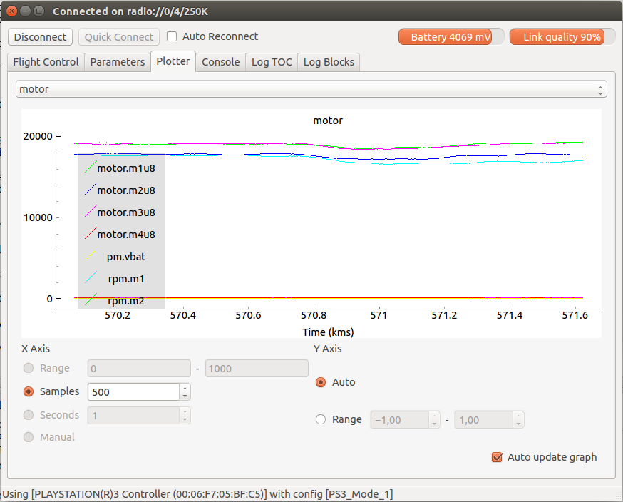
The data can also be plotted in real-time using the plotter as in the picture below. Hmmm, interesting, the Crazyflie 2.0 seems to hover at about 19000 rpm with the RPM measurement board attached.

plotting of rpm


The idea was to do the analysis part in this post as well but it turned out to be a little bit to much, therefore stay tuned for the final analyzing part!

During the last week there’s been lots of work, but we don’t have that much to show for it. We’ve spent a lot of time discussing what we should do during 2015. Last year there was a clear focus: develop, release and ship the Crazyflie 2.0. But up until now we haven’t really discussed what the goals for 2015 are. It’s not that we don’t have ideas, there’s always lots of ideas. It’s more about finding a common focus to work towards. It’s still ongoing, but there’s a few points that we know. We will of course continue the development (firmware, software, clients) of the Crazyflie as well as creating more expansions for the Crazyflie 2.0. For the expansion boards we’ve already talked a bit about it before, but for the firmware/software side we haven’t communicated our plan. The reason for this is simple, there’s not really been a plan for this. The main focus has been stabilization and creating clients for iPhone and Android. But now that it’s done we need to move forward with new features. If you have any feedback on this please let us know. Something that we are hoping to work on is ROS integration. (Edit: well, what do you know, this has already been started by Wolfgang Hoenig, the power of open source! Here’s a link) Once we figure out the plan we will let you now :-)

Fred, the main developer of the Crazyflie Android client, is doing a presentation about the Crazyflie at FOSDEM next weekend. Arnaud will be attending as well so if you would like to meet up, let us know!

But a few things happened during last week:

  • There’s a new release of the Android Client (thanks Fred!), so make sure to upgrade your apps!
  • We’ve added LED-ring settings to the FlighTab in the latest version on the develop branch of the client.
  • We released a bug-fix version of the python client. This new version fixes Crazyflie 2.0 configuration.
  • We added a some guideline for contributing to the client. We hope to streamline the contribution process to be more efficient at it. Tell us if you have any comments.

As for the RPM measurements and analysis we’re working on it, but it’s not ready yet… We are however making progress and it’s been very interesting, have a look at the thrust fixture we made :-).

cf2 thrust fixture

We have had numerous request to get a transfer function from the motor PWM output to propeller RPM. The next step would then be to get the propeller RPM to thrust transfer function as well. With that it is easier to do calculations on the system and mathematical models. So this and probably next post will be about how to obtain this function and also give a bit of insight in how one can do development with the Crazyflie 2.0.

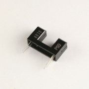
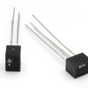
First thing how do one do propeller RPM measurement? A quick search on the internet and you will find that using an optical switch is a common method. I also found this guide written for Arduino which was a great start. Since I preferable wanted to measure the RPM while flying the switch needed to be small and lightweight. I found two types that could be useful. A slotted type and a reflective type. The reflective type, QRD1114, is small and promising but would it work? I got some of each type just in case.

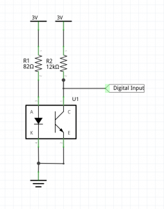
Now the optical switch needs interfacing and power. Sparkfun made a good tutorial using the QRD1114 sensor so I will not go into details. Since we use 3V instead I adjusted the resistor for the LED to 82 ohms instead. This will give me ~20mA emitter current. I also played a bit with the sensor output pull-up resistor. If you go with a to strong pull-up, the sensor will need a lot of light to pull it down and if it is to week, it will rise to slow. 12k pull-up seams like a good compromise in my lighting conditions.

Optical switch circuit


As a first thing I wired it up on a breadboard using the Crazyflie 2.0 breakout board to get a sense if it would work or not. My finding by measuring the output signal with a multimeter is that it is pretty sensitive to surrounding light but that could be solved by flying in a dim room since it is mainly intended to be used for research.

Now it was time to build a circuit using the prototyping expansion board. I also multiplied the circuit 4 times so I can measure all 4 motors. The inputs I use was TX2, RX2, IO2 and IO3. This because they are all connected to timers so I could use the input capture timer functionality later when I get to the software part. Bending the legs on the QRD1114 was a pretty fiddly job but worth it as it came out so cool in the end. Before I connected it to the Crazyflie 2.0 I measured the current draw and it all seamed OK, ~80mA (4 x 20mA). I also double checked all the connections since it is easy to put a lot of time thinking it is a software fault later if things aren’t working as they should.

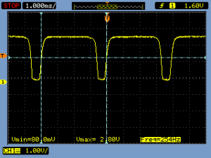
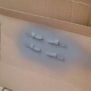
As a first test I just turned on one of the motors at a PWM of 10000 and measuerd the sensor output with a scope. The black color of the propeller wasn’t so good so I searched around in the office and found some reflective paint we used a while ago. I painted the backside of the propeller and it made a big difference. In the pictures below you can find the scope picture using a 12k pull-up and some pictures of the painted props.

Next part I will start doing the software and analysis so stay tuned!

The Crazyflie 2.0 supports two types of radio protocols out of the box: ESB (Enhanced ShockBurst) for Crazyradio/Crazyradio PA USB dongle compatibility and  Bluetooth LE for mobile devices. All Crazyflie 2.0’s are shipped with a radio bootloader, able to update virtually all the different parts of the firmware running in Crazyflie 2.0. We thought we would do a post to explain a bit further how it all fits together. Even though the Crazyflie 2.0 supports Bluetooth LE, the preferred way is to use the Crazyradio/Crazyradio PA when doing development. Flying via Bluetooth is very practical since there’s no additional hardware needed except for a mobile device, but the Crazyradio/Crazyradio PA has minimal latency, more bandwidth and works easily with computer. This makes it ideal for development and other advanced usage.

(On a side note, some of our products are currently out of stock (like the Crazyradio PA and LED-ring). We have started the next batches, so they should arrive soon. Until then have a look at our distributor page to find our products.)

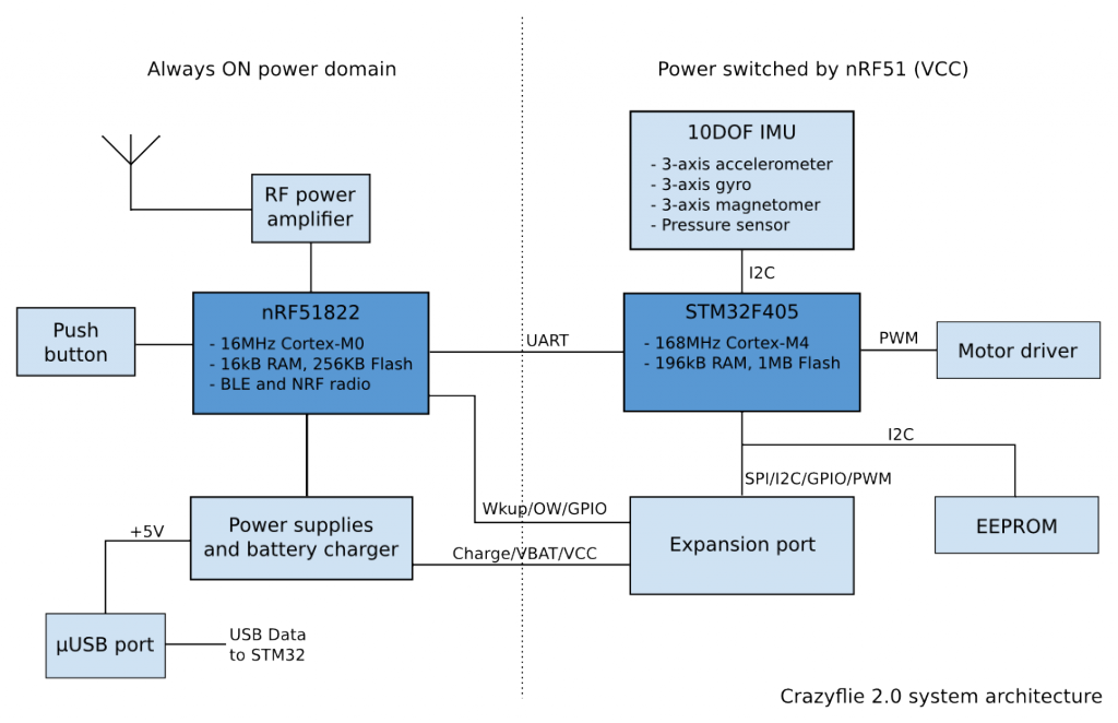
Crazyflie 2.0 architecture

For the radio of Crazyflie 2.0 we choose the nRF51822. The great thing with this chip is that it integrates a radio compatible with our existing Crazyradio USB dongle as well as with Bluetooth Low Energy. The nRF51 also integrates an ARM Cortex-M0 MCU enabling radio protocols to be implemented directly in the chip. However this MCU is not powerful enough to be used by itself in our quadcopter development platform, so we put a powerful STM32F4 Cortex-M4 168MHz on the side to do the heavy work.

The nRF51 mainly handles radio and power management and the STM32F4 handles all the rest: flight control, expansion port, log, param, etc. As far as the radio is concerned the nRF51 act as a bridge: CRTP packets are received by the nRF51 and sent unmodified to the STM32F4 and the STM32F4 sends raw CRTP packets to the nRF51 that transmit it by the radio. This means that the STM32 firmware is unaware of the physical communication protocol, it can be Bluetooth, Shockburst or something else, it makes no difference it is still CRTP packets. CRTP is the protocol used to control Crazyflie, it encapsulates all commands and messages exchanged between the client and the Crazyflie.

Enhanced Shockburst (ESB)

Enhanced Shockburst is a radio physical protocol implemented in some Nordic Semiconductor 2.4GHz radio chips. In the nRF24 chip, used by Crazyradio (PA) and the original Crazyflie, this protocol is implemented in hardware and we have little control over it. The nRF51 used in Crazyflie 2.0 offers more control on the radio physical packet and ESB since it’s implemented in software instead.

ESB handles ack and retries: The Crazyradio sends a packet on a given channel and waits for an ack. If a Crazyflie receives the packet without error it sends an ack packet. If an ack is received, the Crazyradio can send the next packet. If no ack is received Crazyradio will automatically retry by sending the same packet again. The current implementation will retry to send a packet forever, so all packet are guaranteed to be transmitted as long as a Crazyflie is in range. Packets are sent back by the Crazyflie by adding a data payload to the ack packet. Close to 80 different channel can be used and every packet is sent with an access address, so more than one Crazyflie could share the same channel.

Enhanced Shockburst using the Crazyradio (PA) offers the lowest latency that can be expected. The minimum latency to send a packet is estimated to about 2ms (1ms minimum for USB and 1ms measured latency for the radio at 2Mbps without any retries). With the Crazyflie 2.0 and the Crazyradio PA it also offers the maximum range with 20dBm power output.

For the original Crazyflie there is an implementation of the E-sky RC transmitter protocol. This permits controlling the Crazyflie directly from an RC transmitter. It is technically possible to implement this protocol in the Crazyflie 2.0 nRF51, but it hasn’t been done yet.

Bluetooth Low Energy

In the Crazyflie 2.0 Bluetooth low energy is implemented as a CRTP bridge: CRTP packet are written and read using Bluetooth. This simplifies greatly the implementation, but does not make full use of the Bluetooth LE functionality. It is planned to add more Bluetooth capabilities for things like communicating the battery status and being able to switch ON or OFF the Crazyflie with a mobile devices.

On the nRF51 side the Bluetooth functionality is implemented using the Nordic Semiconductor S110 Bluetooth stack. This stack runs independently of the firmware. Nordic calls this a softdevice and it’s a fitting description of how it works. It almost looks like a hardware device from the firmware point of view as it is not linked into the main firmware.

However we do not currently have the right to distribute the supporting files for the stack, so unfortunately you will have to download them yourself if you want to compile your own nRF51 Bluetooth firmware. To do so you must own a Nordic Semiconductor development kit. Even though some of the kits are pretty cheap, we do not like this situation at all so we are working on solving it. However we made sure that it is possible to compile the nmRF51 firmware without Bluetooth, to avoid the added dependencies. This means that you can still build your own nRF51 firmware to work with a Crazyradio/Crazyradio PA.

Bootloader/firmware upgrade

The Crazyflie 2.0, like the original Crazyflie, is upgradable wirelessly with radio. The radio bootloader has been enhanced to work both with ESB and Bluetooth LE. Both nRF51 and STM32F4 can be upgraded and it is even possible to upgrade the nRF51 Bluetooth stack and bootloader.

Currently the bootloader is working with Crazyradio on ESB. Bluetooth implementation for iPhone and Android is still work in progress. The STM32F4 can also be upgraded via USB and so, for people that does not have a Crazyradio, the first Crazyflie 2.0 firmware upgrade has been released for USB DFU as well as the classical radio bootloader update package.

This week is going to be an exiting week! Crazyflie 2.0 has started to ship and we are pushing out a lot of code during the week. We wish that we would have gotten more time to work on the code before releasing it, but all three of us have been really busy with production. With the first units now shipping we can finally switch focus to software and documentation. Since there’s quite a few source code projects we are releasing, they each get its own bold headline below. As we role out the different releases we will update this post and post the link in social networks.

iOS Client

main_screen_joysticks_appimg

iOS joystick screen – Download on Appstore

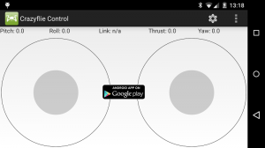
This is our first ever iOS app, and it’s just been released. It got accepted just in time and you can get it from the AppStore, free of course. Currently it is pretty simple, you can connect to a Crazyflie 2.0 and fly it with thumb controls. There is a settings menu where you can adjust sensitivities and configure mapping. The app is all open source and the code can be found here on Github.

Android Client

main_screen_with_app

Android joystick screen – Android app on Google Play

This is more or less the same as the client that has been available for the Crazyflie Nano Quadcopter, but now we have added Bluetooth LE support. Since this app has been manged by our community member Fred for a while it has more functionality then the iOS app, such as tilt control. One cool feature is that you can connect a gamepad with a USB-OTG cable to the phone to get better flight precision with real thumb sticks. The app is all open source and the code can be found here on github. Thanks to Fred Sauer the Crazyflie app has been available for a while now on the market, but now we have taken over the ownership of it. Due to a change in the certificate used to sign the app you will have to re-install the application to get the latest version (market link).

PC Client

The PC client written in Python has got some new features to support the Crazyflie 2.0. E.g. the bootloader in Crazyflie 2.0 is different as it now contains two MCU. It also has a EEPROM which needs new functionality, but other then that we are trying to keep things as common as we can to make things easier. The code is all open source and the code can be found here on Github. Edit: We have made a new tag (2014.12.1), source-code is available here and a windows installer is available here.

Crazyflie 2.0 Firmware – STM32

This firmware is based from the Crazyflie Nano Quadcopter firmware and the aim is to merge the old and new code, but we haven’t had the time to do it yet. Therefore it is now located in its on crazyflie2 branch on Github. We plan to merge them together but more work needs to be done before this is possible, a perfect job for the cold and dark winter months here in Sweden.

Crazyflie 2.0 Bootloader – STM32

This is the code that can flash new code into the STM32F405 MCU. Now the data comes from the nRF51 MCU over the uart, so the booatloader had to be updated. The code is all open source and will be released later this week on Github.

Crazyflie 2.0 Firmware – nRF51

This firmware is completely new and handles the radio communication (Bluetooth LE and Shockburst, compatible with Crazyradio). It also handles the power management and the expansion boards 1-wire memories. The code is all open source and will be released later this week on Github.

Crazyflie 2.0 Bootloader – nRF51

The program to load new code into the nRF51 over the radio link. It also boots the STM32 in bootloader mode and serves as a radio gateway to be able to flash it. The bootloader handles Bluetooth and shockburst so that not only the PC client but also future version of the mobile apps will be able to update the Cazyflie 2.0 firmware. The code is all open source and will be released later this week on Github.

Hardware

We have not yet had time to finalize the hardware files. We are reorganizing the kicad lib and we need to clean things up properly. The hardware projects therefor have to wait, but the schematics has been released if anyone needs to see how things are connected.

Winner of the expansion board naming contest

We have now done a local vote. We are almost hundred percent sure this voting was not tampered with. And the winner is… Flykit. So even though Flykit got a lot of “proxy” votes online it seems the local people liked the same thing. Deck finished second, strange, maybe the voters had read the online vote results… Anyway congratulations to Ramin who will receive a Crazyflie 2.0! We still have not decided if we should go with Flykit or Deck for the real expansion board name. As soon as we have decided we will let you all know.

Starting up production and doing the first batch of a product is always problematic, no matter how well you try to plan it. So just like for the Crazyflie 1.0, we decided to pack our bags and leave for Shenzhen for the production of the first batch of the Crazyflie 2.0. When we launched the first Crazyflie we tried to take things easy and minimize the number of products we launched at once. But for the Crazyflie 2.0 we went all in and launched 13 new products at once. Some of these are just spare parts, but many are more complex products. It’s been a few busy months to say the least :-)

Production

The production timeline that we have been working towards for the Crazyflie 2.0 has been pretty tight. So our main goal with this trip was to help out in any way possible to make sure that everything was going smoothly. Like I wrote above, we are launching a fair amount of boards at the same time. The Crazyflie 2.0 itself is of course the most complex, but also the Crazyradio, the LED-ring and Qi expansion requires a lot of attention. Aside from that there’s also the debug-kit and prototype/breakout boards as well as all the spare parts that should be inspected. Everything started off very well and things was going ahead of schedule, somehow we became the ones slowing things down. We had to work almost around the clock to catch up. In the end though it was all worth it because on Saturday it all came together and everything was following schedule.

Delivery

Since things are running according to the schedule it means the products will start to ship Monday the 8th of December. So if you have chosen Air mail there is a big chance it will reach you before X-mas, but not guaranteed. If you have chosen a faster method, DHL or UPS you will get your pre-order before X-mas.

Getting to Shenzhen

Going from Sweden to Shenzhen is a pretty long journey, but that doesn’t mean it has to be super expensive. Since Shenzhen is very close to Hong Kong, the easiest for us have been to fly to Hong Kong and take the bus/train to the border at Lo Wo (map). The bus ride takes over an hour, but it’s filled with beautiful views of Hong Kong so time passes quickly. Once you are at Lo Wu you can walk across the boarder to mainland China and go directly down into the metro. While entering the metro it’s easy to pick up a Chinese SIM card for your phone and a metro card. The Chinese SIM we got was about 15 USD which also includes 300 MB of data. If you are on your way to Seeedstudio then make sure to check out their guide for getting there.

Huaqiangbei

If you are an electronics enthusiast or just like electronics you need to visit Huaqiangbei in Shenzhen. It is the worlds largest electronics market and things that can’t be found here, I’m not so sure it can be found at all. The prices are extremely low but be aware of fake products and quality problems. E.g if you buy a cheap 32GB SD card you can almost be sure it is a fake and only holds a true 4 – 8GB, so we can’t recommend you to get one there. Many guides has been written about Huaqiangbei so we won’t write yet another one. If you want to read more we can recommend dangerousprototypes guides.

Expansion board naming contest results postponed yet another week

After checking the voting log we could see that most of the naming alternatives had been tampered with. We had some idea that maybe we could filter out the suspicious ones but our attempt failed so we are back on square one. We still want to give away a Crazyflie 2.0 kit to the winning name but we more or less decided to have a local voting process with people aorund our office instead. We will therefore need more time to select the winner. As we won’t be able to ship the award unit before the 8th of December anyway so we decided to postpone it yet another week to be able to gather the local votes, which will be a lot harder to tamper with. So be sure to check back next Monday.

Wow, we are a bit overwhelmed with all the naming suggestions we got for our expansion board last week. It’s fun to see so many people joining in and having an opinion, thanks to everyone that dropped a suggestion. After discussing it we decided to put favorite suggestions into a poll and see what our readers likes the best. Make your voice heard and take part in the voting below! And in case anyone missed it the winning contribution will get a Crazyflie 2.0 developer pack.

What should be name of the Crazyflie 2.0 expansion boards (tampered with)

  • Flykit (36%, 242 Votes)
  • Deck (32%, 215 Votes)
  • Bitboard (11%, 77 Votes)
  • Crazymod (6%, 39 Votes)
  • Payload (4%, 26 Votes)
  • Flieboard (3%, 19 Votes)
  • Pod (3%, 19 Votes)
  • Fliekit (2%, 16 Votes)
  • Companion (1%, 10 Votes)
  • Avionic (1%, 10 Votes)
  • Fliemod (1%, 5 Votes)

Total Voters: 678

Loading ... Loading ...

In other news we are spending the week in Shenzhen in China, visiting Seeedstudio and helping out with the testing of initial production samples. So far everything is on track and today we got to fly the first mass produced Crazyflie 2.0! Here’s a picture of it before we broke it loose and got it into the air. Next week we will post lots of updates and photos from our trip. Until then, don’t forget to vote :-)

first_cf2

As everyone probably knows by now, one of the new features of the Crazyflie 2.0 is the improved expansion port. It’s something that we’ve been putting a lot of effort in and we’re really looking forward to see what you will do with it. However a couple of weeks ago we realized something: We don’t have a good name for the expansion boards. Arduino calls them sheilds, the Beaglebone capes, but what should the Crazyflie’s boards be called? Up until now we have just been calling them “expansion board”, like “LED-ring expansion board”.  As far as we know this is the first flying platform that has this type of expansion port, and we think it deserves a cool name. Don’t you? We have been trying to come up with something ourselves and our current best idea is “deck”, as in the different levels on an airplane. But we’re a bit stuck there, we haven’t come up with something else and we think there must be a better name then “deck”.

So we thought that we would turn to our readers and community for help. In order to find a name to call our expansion boards we thought we would organize a little competition this and next week. For this week we would love to get some ideas in the comments for naming and then next week we will do a poll to vote for a winning contribution. To sweeten the deal we thought that we would  throw in a Crazyflie 2.0 developer edition (which includes debug-adapter, proto- and breakout board and a Crazyradio PA) to the first comment that holds the winning contribution. But before everyone beings posting ideas, here’s a few rules:

  • Only one idea per comment, if you have more then post more comments. By posting an idea of the name you give us the right to use it, otherwise there wouldn’t be much point in posting it ;-)
  • Our WordPress is set-up for reviewing posts before they are accepted, but once you are accepted as poster you can freely post. This means that some comments will appear directly and some won’t. But to judge whoever is first we will use the timestamp of the comment.
  • The best ideas will be collected in a poll next week. Then everyone will get a chance to vote for the name they think is best during the week and then a winner is selected
  • The winner of the poll is the one with the highest number of votes and this user will receive a Crazyflie 2.0 developer edition. But even if everyone likes the name we still reserve the right to use something else, but you will still get the price :-)

So start brainstorming and get the chance to be the inventor of the Crazyflie expansion boards name! Also the winner of a Crazyflie 2.0.. :-)

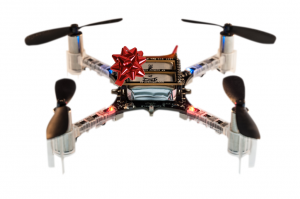
cf2 front rosette

At the moment we are just overloaded with work and we haven’t had time to be so active in the forum lately. We feel really bad about this and hope things will change as soon as the Crazyflie 2.0 is starting to ship. Until then we hope our community can step in and help us out, it would mean a lot to us. We have already got a lot of help from Chad, thanks a lot for that Chad and others! For urgent matters you can still reach us at our contact address found in the about page.

Oh, one last thing. The manufacturing of the first batch of Crazyflie 2.0 it’s still on track and no delays to report. When we have any updates on a final estimated shipping date we will let you know.

The production of the first Crazyflie 2.0 batch is still on track. Currently all the components are being purchased and when they are all in, the assembly will start. We are still busy preparing things for the production, but we have now slowly shifted over to software and firmware development. The last week has been spent implementing the bootloader and implementing our communication protocol (CRTP) over USB support.

The bootloader has gone from a simple piece of firmware to something that’s more complex. For the Crazyflie 2.0 we have a dual-MCU architecture, which means that we have to flash two MCUs instead of one. Aside from that we now also support bootloading via Bluetooth LE as well as the enhanced shockburst protocol. Another fact that complicates things is that the nRF51 uses a closed binary for it’s Bluetooth LE support, which means we have to take special care when upgrading it. But the trickiest part of all this is to make it safe so that it’s always possible to rescue the system without needing a JTAG/SWD dongle if something goes wrong. It’s important to get it right, since the bootloader is flashed during production it can’t be updated at a later stage without using JTAG/SWD.

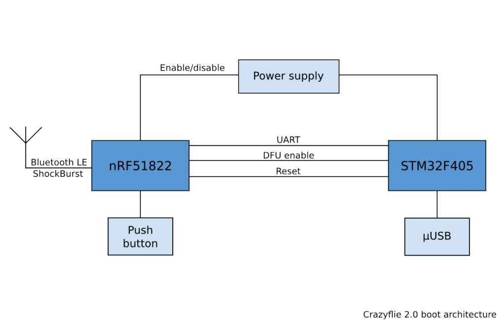
The Crazyflie 2.0 only has one button and it’s connected to the nRF51. Instead of directly switching on/off the power to the platform like on the Crazyflie 1.0, the button is now multi-functional. Pressing it will turn on/off the power and put the nRF51 to sleep, but holding it down when powering on the Crazyflie 2.0 will affect the start-up behavior. By holding it down 1.5 seconds the bootloader will launch and by holding it down 5s the STM32F4 will start in DFU mode (Device Firmware Upgrade). One of the reasons for designing in the DFU functionality was to use it as a last resort to rescue the system in case we couldn’t make the nRF51 bootloader secure. Another reason for it is that we always try to design in lots of possibilities, even if we can’t find a use for it we are hoping someone else will.

Crazyflie 2.0 boot arch

CRTP over USB is something that’s been on our TODO list for at least 2 years, but we have never gotten around to it. One idea we had was for building a bigger quadcopter using a Raspberry Pi and a Crazyflie connected to it via USB. The Crazyflie would still be used as the real-time control board, but would receive commands on the USB. This would allow the Crazyflie to become a quadcopter control board using our normal Python API for commands from Linux. This way we could for instance create a higher level autonomous system. But now we needed it for one of our test-rigs, so we had to sit down and get it done. For the implementation we use a raw USB device (i.e class 0) where we use the end-points to send CRTP packets back and forth from the PC. Since a CRTP packet is smaller than a USB packet, there’s no need for flow control or any extra protocols, we just receive new packets on the OUT requests and send a new packets back on the IN requests (if there’s any available). This fits nicely into the current architecture of the Crazyflie Python Lib and the firmware, but it still needs some cleaning up. Once everything is done it will be merged into the main firmware as well.