During the last week we’ve taken a big step, moving to Python 3! The reason for the move is that Python 3 is becoming broadly adopted and it has more features that we want to make use of. Also 3 > 2. This post will explain a bit of what we did, some of the problems we encounters and the current status. The numbers 2 and 3 will be thrown around a lot in the text, but to precise we’re talking about versions 2.7+ and 3.4+ (even more precise it’s been tested on 2.7.9 and 3.4.3). The next release of the client will run on Python 3, but if you want to test it now just clone the development branch on GitHub.
Status
If you have developed applications using the API and Python 2 then you might be getting a bit worried right about now. The compatibility for both Python 2 and 3 will be kept for most things, except for the client:
This will be compatible with both 2 and 3:
- The Crazyflie Python API (everything in lib/cflib)
- The examples for the Crazyflie Python API (everything in examples)
- The ZMQ server using the Crazyflie Python API (bin/cfzmq)
- The Crazyflie command-line bootloader (bin/cfloader)
But the main clients will only have Python 3 compatibility:
- The Crazyflie Python client (bin/cfclient)
- The Crazyflie Python headless client (bin/cfheadless)
API Examples
While doing the porting we’ve also added more examples to cover more of the Crazyflie Python API. In order to keep 2/3 compatibility for the API it’s important to be able to test it easily with the different versions. We are having unit-tests on the TODO-list, but until then we’ve been using the API examples to test. All the examples should run with both Python 2 and 3. It’s also a good thing with more examples showing how to use the API…
Porting and compatibility
The approach we used was to first run the 2to3 utility to automatically to as much as possible of the porting. After that we had to fix the rest of the errors manually and also maintain the dual 2/3 compatibility of the API.
In our previous implementation we made use of strings to store binary data that we were sending/receiving. But because of incompatibilities between Python 2 and 3 this didn’t fit very well. To make things neat for the API we found a container where we could store bytes that works with both Python 2 and 3, the bytearray. Even though we use the same type, there’s still some subtle differences in usage between the versions. After doing some testing we found ways where the syntax was the same for Python 2/3.
First of all bytearrays can be created from a string, tuple or list. When indexed by the [] operator it will give you the value of each byte.
>>> d = bytearray([i for i in range(10)])
>>> d
bytearray(b'\x00\x01\x02\x03\x04\x05\x06\x07\x08\t')
>>> d[5]
5
The main point is getting something meaningful out of the bytearray when doing the communication, here’s a few examples:
Unpacking a byte, an integer and a word from the first 7 bytes (little endian)
>>> struct.unpack("<BIH", a[:7])
(0, 67305985, 1541)
Getting a string from a subset of the data can be done by using decode and the char-set to use for decoding. We use ISO-8859-1 since the Crazyflie does not support Unicode (yet?).
>>> d = bytearray([i for i in range(97,100)])
>>> d
bytearray(b'abc')
>>> d.decode("ISO-8859-1")
'abc'
You can also easily get a tuple or a list:
>>> list(d)
[97, 98, 99]
>>> tuple(d)
(97, 98, 99)
And you can also concatenate:
>>> d + d
bytearray(b'abcabc')
And find a byte:
>>> d.find(bytearray((98, )))
1
But there’s also a few things we couldn’t get to work in a good way and have to check which version we’re running and execute different code, like the queue import that has changed name.
if sys.version_info < (3,):
    import Queue as queue
else:
    import queue
Another problem we haven’t solved is creating a bytearray from a string, so it’s also
if sys.version_info < (3,):
    self._data = bytearray(data)
else:
    self._data = bytearray(data.encode('ISO-8859-1'))
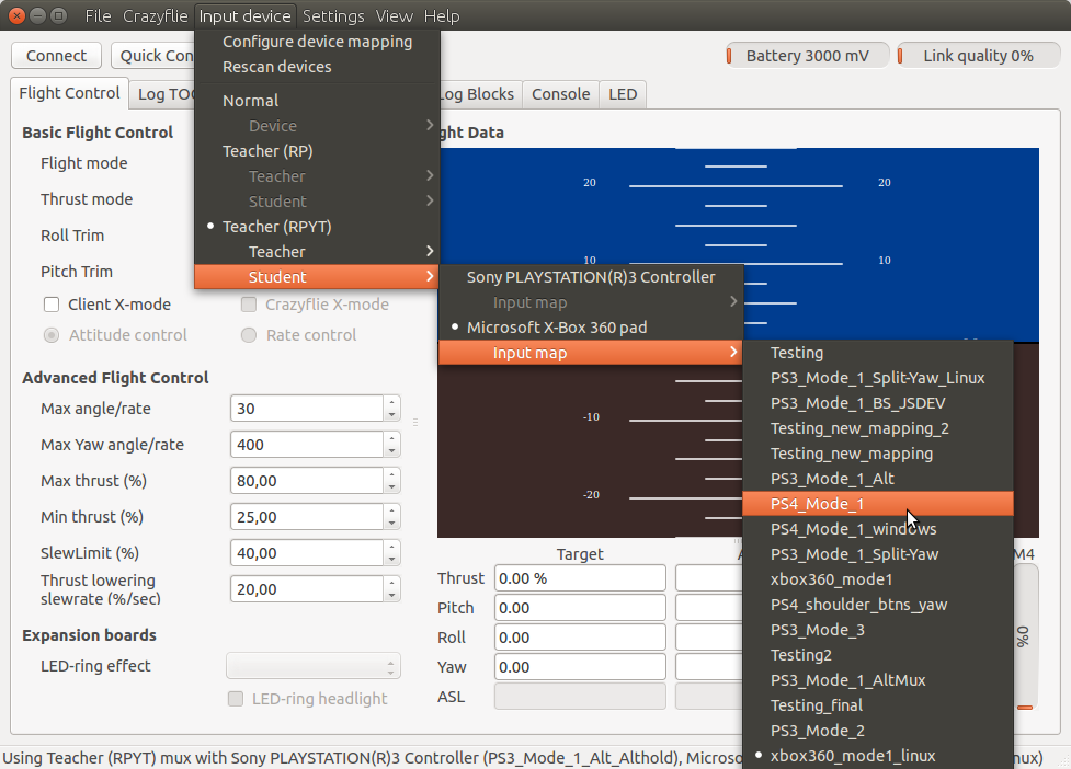
As for the client code that was ported to Python 3 without keeping the backwards compatibility there wasn’t any big issues. The biggest change was the PyQT4 API where there’s a few things that have improved when placing custom Python data in GUI objects. Before QVariant was used for this. You would create a QVariant object that wrapped the Python object. To get data out from the QVariant again you would have to explicitly say what type it had by calling the correct function (like toInt()). Now this is a lot smoother. QVariant has been skipped and you just use the Python type directly.
For more information have a look here where we found a lot of useful tips. Don’t hesitate to leave a comment if you think we could have done things differently or if you have any tips!
What’s not working
There’s still a few things we’re not sure how to fix and we have to look into it a bit more. These are:
- There doesn’t seem to be any Python 3 bindings for the Leap Motion. According to this it’s possible to build the bindings yourself.
- The Python 3 bindings to Marble for the GPS tab hasn’t been investigated yet
PEP-8
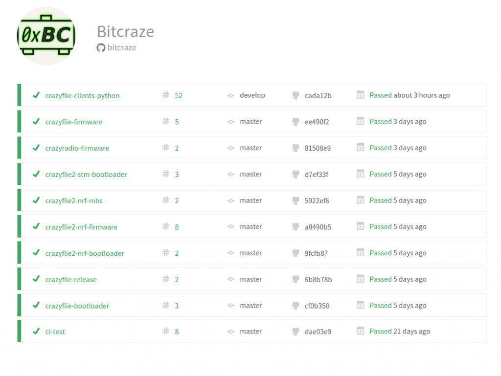
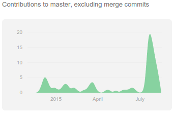
On a side note we’ve started using Travis CI (more on this next week) and will start creating unit-tests for the Crazyflie Python API. As a first step we’re running PEP-8 on all the code. This will be checked automatically for all commits and pull-requests.