We have been working with our indoor positioning system for over a year now and during that time the interest for the Loco positioning system have continuously been growing. Universities all over the world are already using our system and the attention we have received have been very encouraging. But the system has been a bit hard to set up and lacking in documentation. So we decided that this had to be fixed before we could leave early access.
So now we’re happy to announce that the Loco positioning system has reached a state where it’s out of “Early access” and we’re excited to see even more customers starting to use the system. We would like to thank everybody in the community that has been contributing to the project, this is what makes open source great!
Below are some of the steps we’ve taken to make it easier to use.
Getting started guide
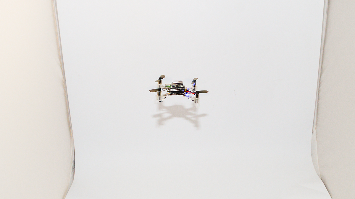
We have created a brand new “Getting started with Loco positioning” tutorial that will replace the old “Getting started” video that we made. The tutorial contains a step-by-step guide for flying one Crazyflie 2.0 autonomously using two way ranging. The more advanced features such as TDoA is still considered as experimental and won’t be covered in this tutorial. We are very happy with the outcome of this tutorial but please help us out and try the tutorial and give us feedback.
LPS tool
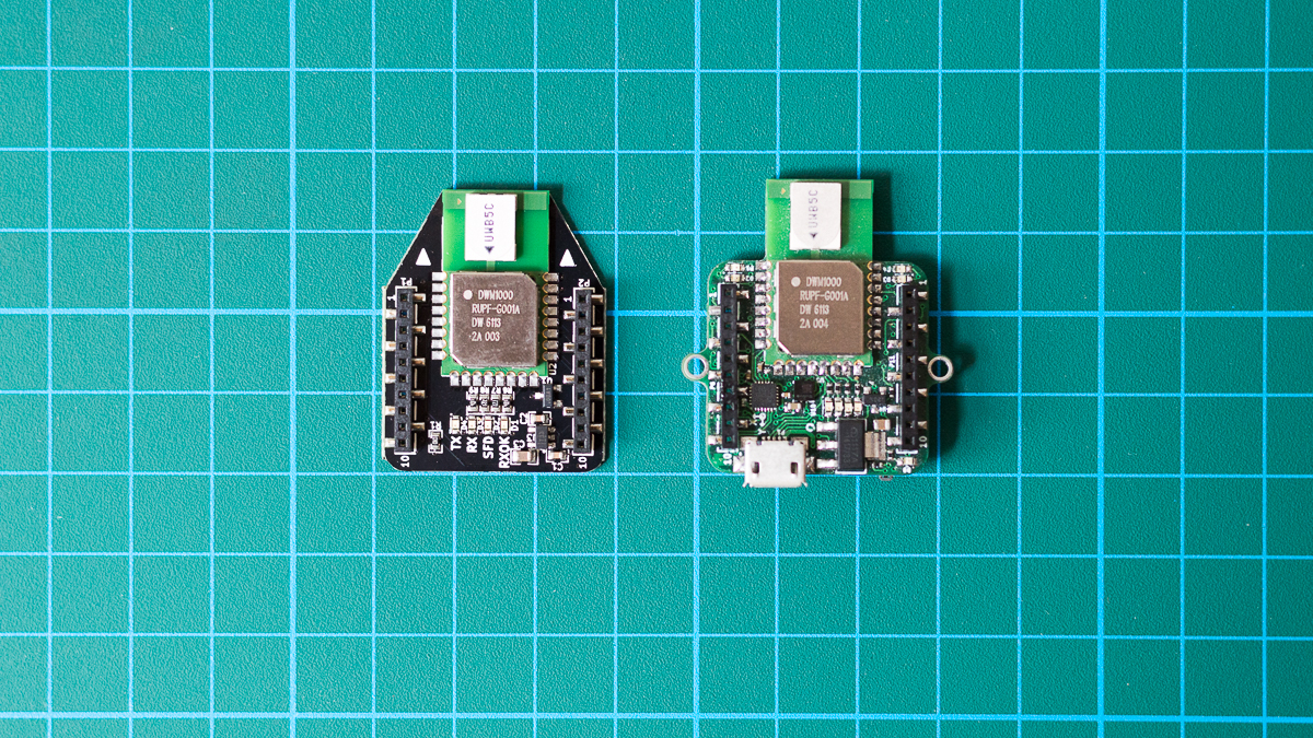
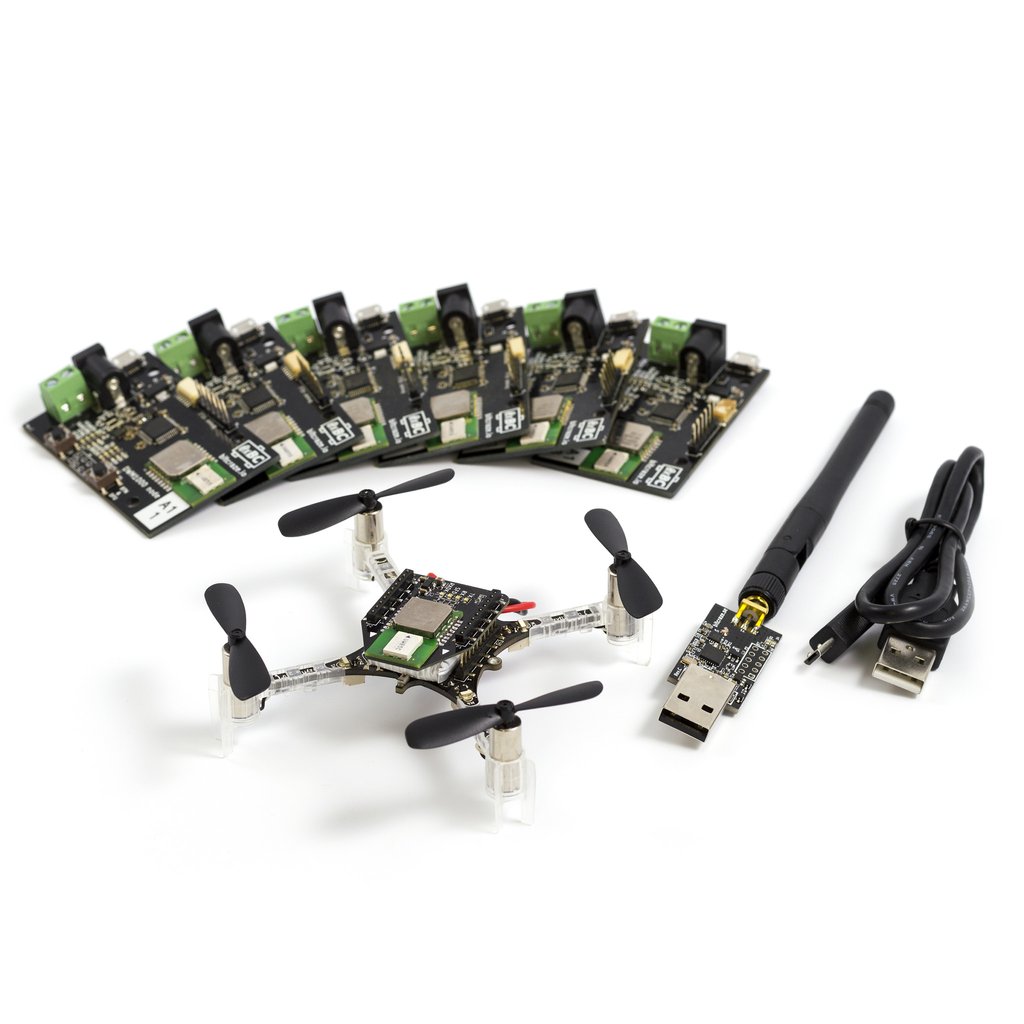
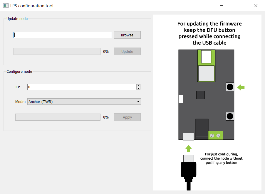
In order to easily configure and upgrade the firmware for the Loco positioning nodes we’ve created the LPS tool. With it you can set the address of the node, the mode and also upgrade the firmware easily.
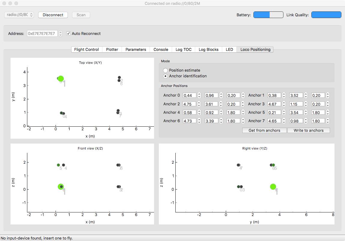
LPS tab
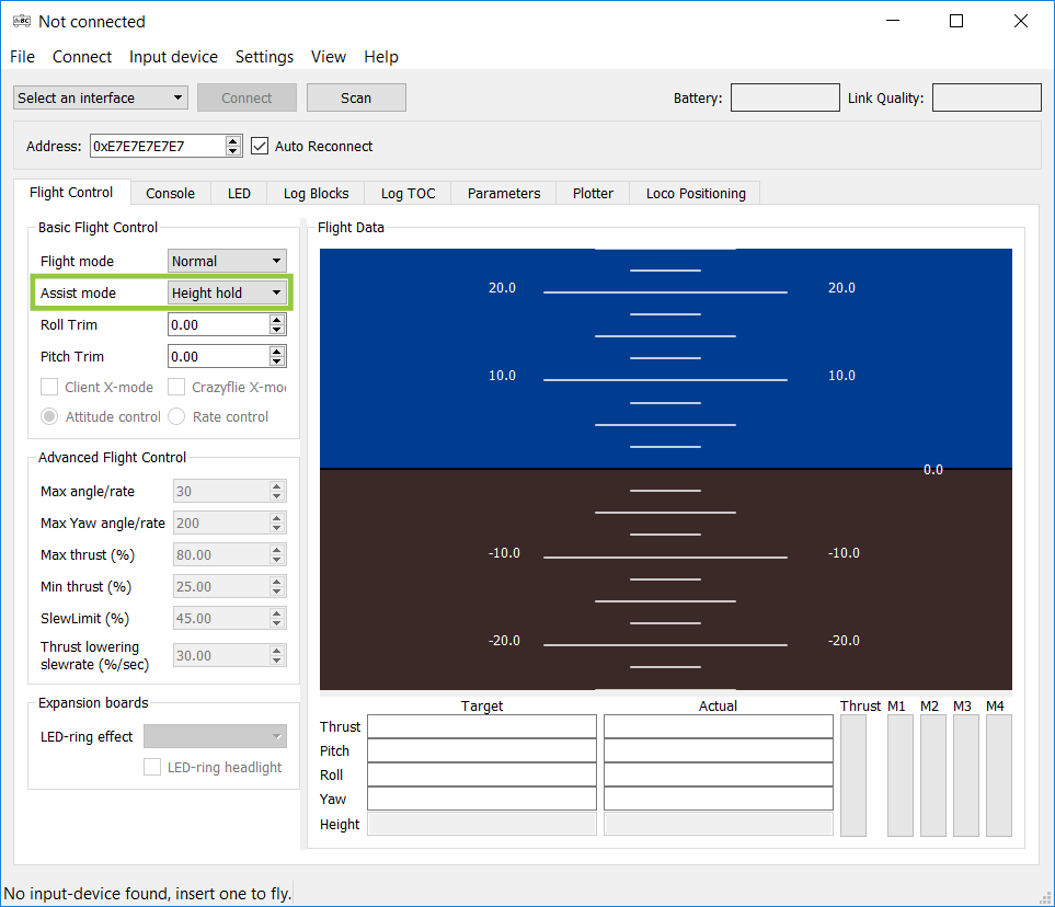
Up until lately there hasn’t been any support for the Loco positioning system in our Crazyflie Python client, instead we’ve been using ROS. It’s a great tool and very powerful tool, but ROS can be a bit complicated with specific requirements on the environment in which it runs. So we wanted to be able to perform basic use-cases directly in our client, like setting up the system, debugging it and flying with it. In order to achieve this we created the Loco positioning tab and a new flight mode called Position hold.
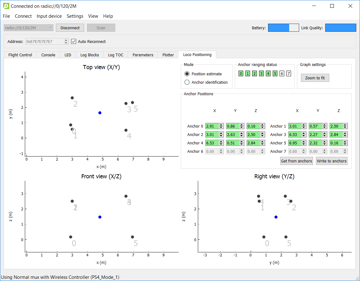
The Loco positioning tab is used to set-up the system and view it’s status. You can configure the position of the anchors, easily see which anchors you’re close to and if all the anchors are responding as they should. It’s also possible to see the layout of the system and the Crazyflies position in it.
For flying the Crazyflie we’ve added the Position hold mode. When enabled this will translate gamepad input into velocity control set-points that are followed using the positioning.
Wiki documentation
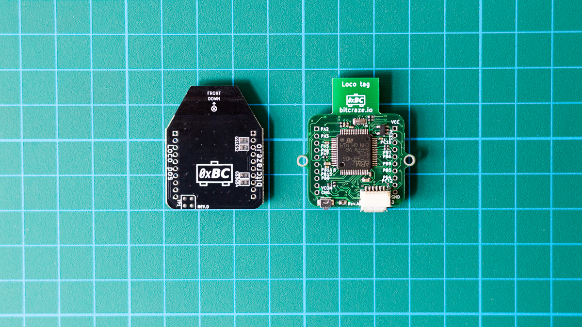
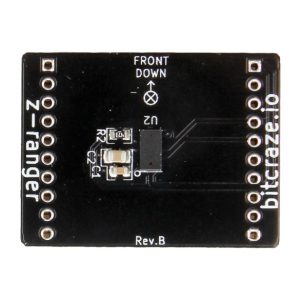
We’ve added technical documentation for the Loco positioning system to the wiki and we’ve also created product pages with schematics and details on the hardware for the Loco positioning node and deck. In the documentation you can find useful things like protocol documentation and details on our reference set-up that we use in our lab. Sine the system is still continuously evolving this is a working document that will continue to be improved over time and we hope to push the boundaries further for swarm flying and robotics in general.
ICRA
Finally a reminder, if your are attending 2017 IEEE International Conference on Robotics and Automation in Singapore you can meet us in booth C08 from 30/5 – 01/6. We will show autonomous flight with the Crazyflie 2.0 enabled by the the Loco Positioning System. Come by have a chat with us and see the Loco positioning in action!
You will also be able to attend the presentation of the paper “Crazyswarm: A Large Nano-Quadcopter Swarm” by researchers from USC during Wednesday 31/5 at 11:15.
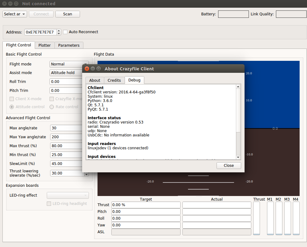
Releases
To support the features mentioned above we’ve released version 2017.05 of the Crazyflie Python client and Crazyflie firmware.