The Flow deck has been around for some time already, officially released in 2017 (see this blog post), and the Flow deck v2 was released in 2018 with an improved range sensor. Compared to MoCap positioning and the Loco Positioning System (based on Ultrawideband) that were already possible before, optical flow-based positioning for the Crazyflie opened up many more possibilities. Flight was no longer confined to lab environments with set-up external systems; people could bring the Crazyflie home and do their hacking there. Moreover, doing research for exploration techniques that cannot rely on external positioning systems was possible with it as well. For example, back in my day as a PhD student, I relied heavily on the Flow deck for multi-Crazyflie autonomous exploration. This would have been very difficult without it.
However, despite the numerous benefits that the Flow deck provides, there are also several limitations. These limitations may not be immediately familiar to many before purchasing a Crazyflie with a Flow deck. A while ago, we wrote a blog post about positioning systems in general and even delved into the Loco Positioning System in detail. In this blog post, we will explore the theory of how the Flow deck enables the Crazyflie to fly, share general tips and tricks for ensuring stable flight, and highlight what to avoid. Moreover, we aim to make the Flow deck the focus of next week’s Developer meeting, with the goal of improving or clarifying its performance further.
Theory of the Flow deck
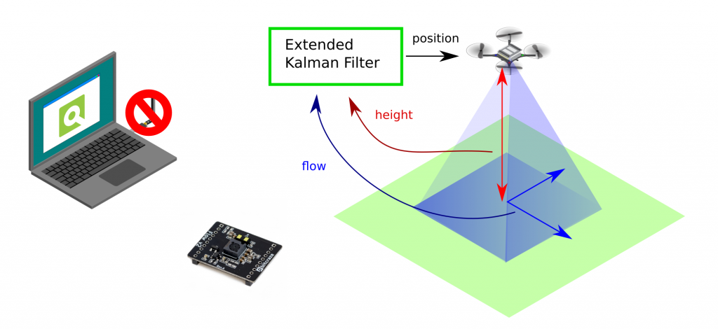
I won’t delve into too much detail but will provide a generic indication of how the Flow deck works. As previously explained in the positioning system blog post, the Flow deck is a relative positioning system with onboard estimation. “Relative” means that wherever you start is the (0, 0, 0) position. The extended Kalman filter processes flow and height information to determine velocity, which is then integrated to estimate the position—essentially dead reckoning. The onboard Kalman filter manages this process, enabling the Crazyflie to use the information for stable hovering.
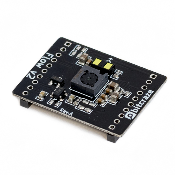
The optical flow sensor (PMW3901) calculates pixel flow per frame (this old blog post explains it well), and the IR range sensor (VL53L1x) measures height up to 4 meters (under ideal conditions). The Kalman filter incorporates a measurement model that describes the relationship between these two values and the velocity of the Crazyflie. More detailed information can be found in the state estimation documentation. This capability allows the Crazyflie to hover, as explained in the getting started tutorial.
If you want to fly with the Crazyflie and the Flow deck, there are a couple of things to take in mind:
Take off from a floor with texture. Natural texture like wood flooring is probably the best.
The floor shouldn’t be too shiny, and be aware of infrared scattering for the height sensor
The room should be well-lit, as the sensor needs to see the texture.
There are certain situations that the Flow deck has some issues with:
Low or no texture. Flying above something that is only one plain color
Black areas. Similar reason to flying above no texture, but it’s more difficult than usual. Especially with startup, the position estimate diverges
Low light conditions
Flying over its own shadow
We made a video that shows these types of behaviors, starting of course with the most ideal flying conditions:
Moreover, it is also important to note that you shouldn’t fly too high or yaw too often. The latter will make the Crazyflie drift, as the optical flow cannot be distinguished as being caused by the yaw movement.
Developer meeting about Flow deck
We believe that many of the issues people experience are primarily due to the invisibility of the positioning quality. In many of our examples, the Crazyflie will not take off if the position is stable. However, we don’t have a corresponding functionality in our CFclient, as it is more up to the user to recognize when the positioning is diverging. There is a lot of room for improvement in this regard.
This is the reason why the next developer meeting will specifically focus on the Flow deck, which will be on Wednesday the 6th of December, 3 pm central European time. During the meeting, we will explain more about the Flow deck, discuss the issues we are facing, and explore ways to enhance the visibility of positioning quality. Check out this discussion thread for information on how to join.
In this blogpost we will teach you how to fly the Crazyflie beyond edges without crashing, using only on-board sensors. Come join in!
Safe flights across edges are achievable!
Introduction
UAVs have seen tremendous progress in the last decades and have since moved from research labs to various real-world environments. Small UAVs (so-called micro air vehicles, MAVs) like the Crazyflie open up even more possibilities. For example, their size allows them to traverse narrow passages or fly in cluttered environments (as recently showcased in this blog post). However, in order to achieve these complex tasks the community must further improve the cognitive ability of these MAVs in order to avoid crashes.
One task on this list and today’s topic is the possibility to fly at constant altitude irrespective of the terrain. This feature has been discussed in the community already two years ago. To understand the problem, let’s look at the currently implemented solution: With the Flow deck mounted the Crazyflie uses a 1D lidar sensor to estimate its vertical position. This vertical position (more or less) equals the current sensor reading. On flat floors this solution works very well. However, if the Crazyflie shall traverse through a narrow window or fly above irregular terrain its altitude will change based on the sensor readings. This can lead to unstable flights, as in the following video, or even crashes!
You might wonder: why not use any of the other great tools from the Bitcraze universe? Indeed, the Lighthouse positioning system and the Loco positioning system work well for absolute positioning (as we have seen earlier, e.g., in this blog post). However, the required setups are often not available in difficult environments. Alternatively, the barometer could be used to achieve a solution based solely on on-board sensors. In fact, Bitcraze has proposed an altitude hold functionality a few years ago. This is a cool feature, but its positioning accuracy of “roughly ±15cm” is not fully satisfying. Finally, relying on the on-board IMU alone will inevitably lead to drifting over time.
Thus, we propose a solution based on the Flow deck and the Multiranger deck. This approach, only based on on-board sensors, allows to fly at constant altitude with obstacles above, below, or even both above and below the Crazyflie. Kristoffer Skare developed this solution when he worked with us as an intern in 2021.
Technical Description
As a first step, the upward-facing lidar of the Multiranger deck is incorporated in the same way the downward-facing lidar of the Flow deck is used in the firmware. This additional measurement can then be used in the extended Kalman filter (EKF) to improve the state estimation. Currently, the EKF estimates and outputs 1 value for the altitude. For our purpose two more states are added to the EKF: one state is defined as the height of the object under the Crazyflie compared to the height where the altitude state is defined as 0. Similarly, the other state is defined as the height of the object above the Crazyflie compared to the same reference height. The Crazyflie keeps therefore track of the environment in order to keep its own altitude constant. To achieve this, an edge detection was implemented: The errors between the predicted and measured distance are tracked in both the upward or downward range measurement. If either of these errors is too large the algorithm assumes that the floor or roof has changed (while the original EKF would think the drone’s position has changed, triggering a change in thrust). Thus, the corresponding state gets updated. For more details on the technical implementation and the code itself, check out our pull request.
Results
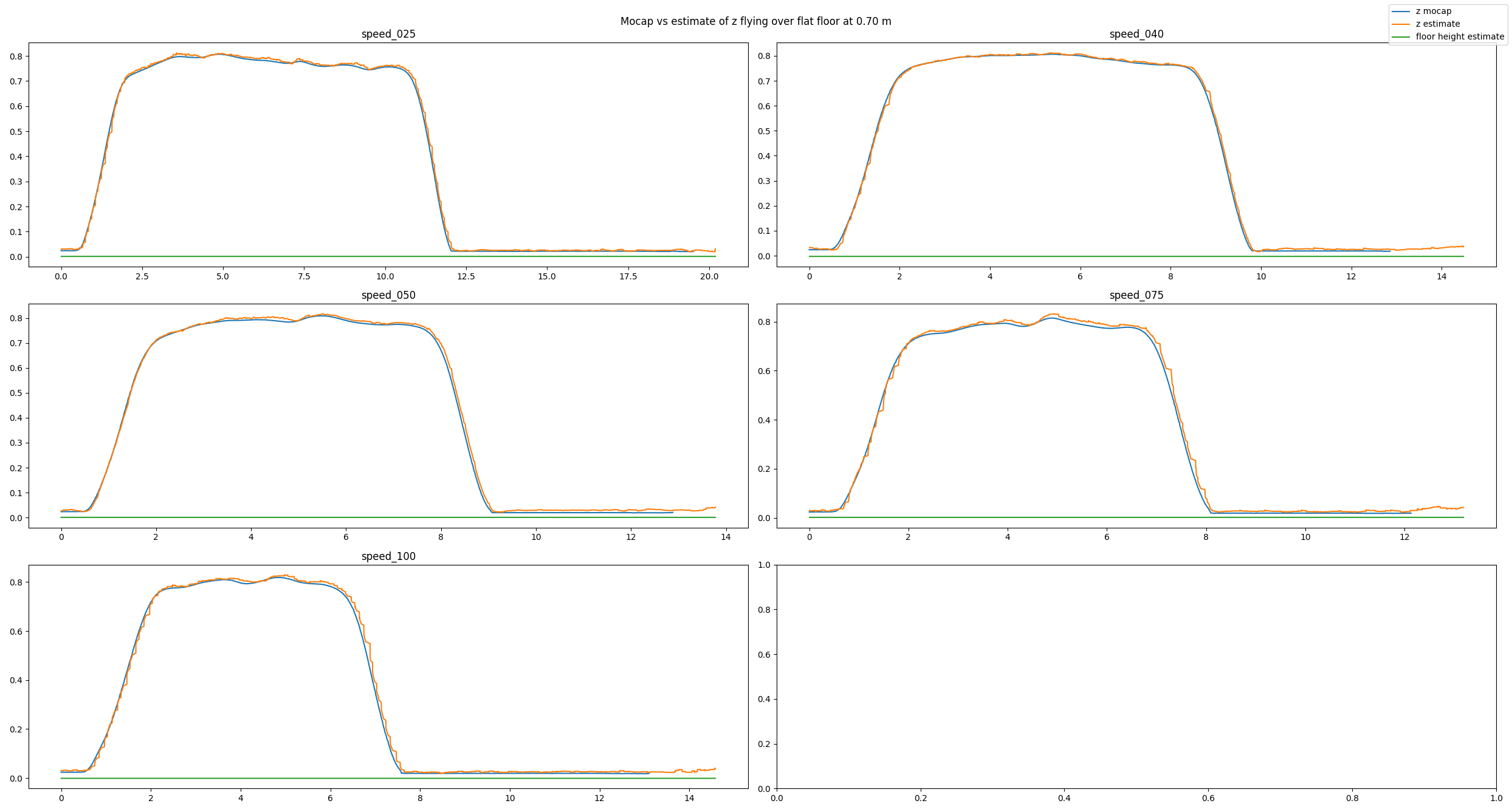
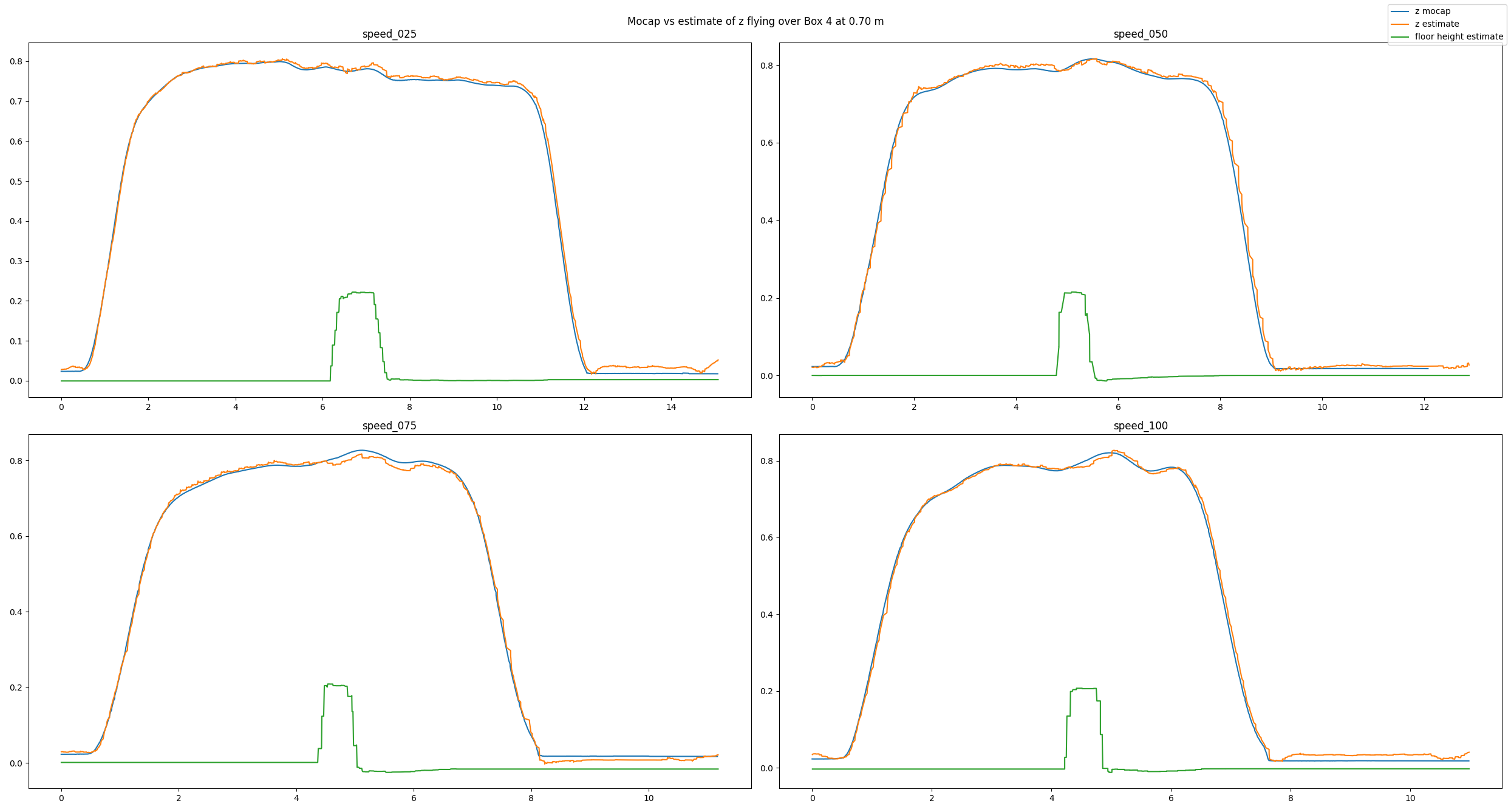
To analyze our approach we have used a Qualisys motion capture system. We have conducted many different tests: flying over different obstacles, flying at different velocities, flying at different altitudes, or even flying under different lighting conditions. Exemplarily, in this post we will have a look at a baseline example, a good estimate, and a bad estimate. In each picture you can see the altitude (in meters) over time (in seconds) for different flight speeds (in centimeters per second). You will see three lines: The motion capture ground truth (blue), the altitude estimated by our code (orange), and the new state keeping track of the floor height (green). For each plot, the Crazyflie takes off, flies in positive x direction, and lands.
In the baseline experiment, it flies over a flat floor. Clearly, the altitude estimates follow the ground truth values well, and the floor is correctly estimated to be flat.
Baseline experiment flying over a flat floor
In the next example, we have added a box with an approximate height of 0.225 m and made the Crazyflie fly over it. Despite the obstacle the altitude estimates follow the ground truth values well. Note how the floor estimates indicates the shape of the box.
Experiment flying over a box
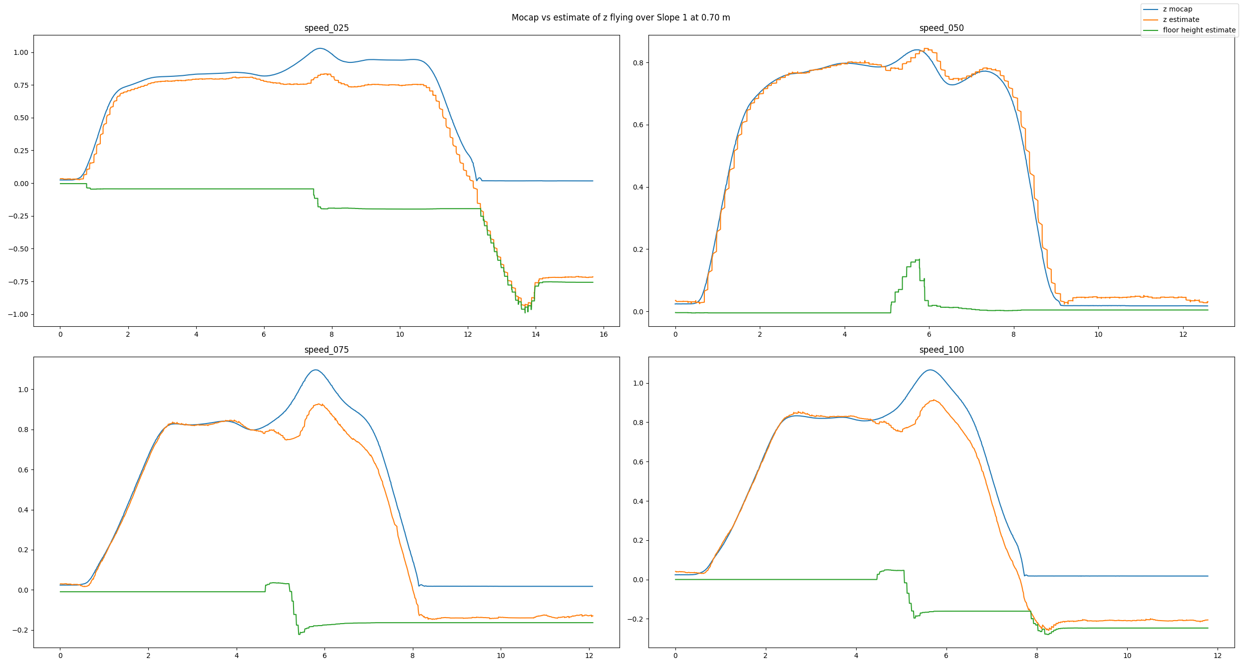
Because the algorithm is based on an edge detection, we had a hunch that smoothly changing obstacles will pose a problem. Indeed, the estimates can be messy as we see in the next example. Here, the Crazyflie flies over an orthogonal triangle, with the short leg at 0.23 m pointing upwards and the long leg with 0.65 m pointing in flight direction (thus forming a slope). For different flight speeds different the estimates turn out quite differently.
Experiment flying over a slope
If you don’t like looking at plots, check out this video with some cool shots instead!
Conclusion
To summarize, we propose a solution for constant altitude flight with Crazyflies, using the Flow deck and the Multiranger deck. We have tested it successfully under various circumstances. Still, we see some potential for improvement, e.g. when dealing with slopes. In addition, the current implementation is quite a change to the original EKF, which poses a problem for integration.
Thus, a way forward can be an out-of-tree build to ease the use of the solution for the community. At SINTEF we certainly plan to deploy this code in all of our tests in 2022, which will hopefully allow us to gather more experience and thus find further ways to improve or tune the system.
We want to emphasize that this is not a perfect solution. That means a) you should use it with care and b) you are very much welcomed to contribute. E.g. feel free to chime in in the pull request, test the code in your environments, propose improvements, or implement an out-of-tree build! :) Maybe you can even come up with an alternative approach for constant altitude flights?
If you want to check out more of our work, visit our website. Also, keep reading this amazing blog from Bitcraze as we try to be back some day (if Bitcraze wants us hehe)!
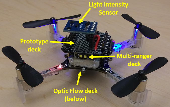
Our team’s Crazyflie quadcopter was equipped with Bitcraze’s Optic Flow deck and Multi-ranger deck. A BH-1750 light intensity sensor was soldered to a Bitcraze Prototype deck to complete our hardware.
The Crazyflie 2.1 was the perfect robotics platform for an introduction to autonomous robotics at the University of Washington winter quarter 2020. Our Bio-inspired Robotics graduate course completed a series of Crazyflie projects throughout the 10 weeks that built our skills in:
Python
Robot Operating System (ROS)
assembling custom sensors
writing new drivers
designing and testing control algorithms
trouble shooting and independent learning
The course was offered by UW Mechanical Engineering’s Autonomous Insect Robotics Laboratory, headed by Dr. Sawyer B. Fuller. The course was supported by PhD candidate Melanie Anderson, who has done fantastic research with her Crazyflie-based Smellicopter. The final project was an opportunity to turn a Crazyflie quadcopter into a bio-inspired autonomous robot. Our three person team of UW robotics grad students included Nishant Elkunchwar, Krishna Balasubramanian, and Jessica Noe.
Light Seeking Run-and-Tumble Algorithm Inspired by Bacterial Chemotaxis
The goal for our team’s Crazyflie was to seek and identify a light source. We chose a run-and-tumble algorithm inspired by bacterial chemotaxis. For a quick explanation of bacterial chemotaxis, please see Andrea Schmidt’s explanation of chemotaxis on Dr. Mehran Kardar’s MIT teaching page. She provides a helpful animation here.
In both bacterial chemotaxis and our run-and-tumble algorithm, there is a body (the bacteria or the robot) that can:
move under its own power.
detect the magnitude of something in the environment (e.g. chemical put off by a food source or light intensity).
determine whether the magnitude is greater or less than it was a short time before.
This method works best if the environment contains a strong gradient from low concentration to high concentration that the bacteria or robot can follow towards a high concentration source.
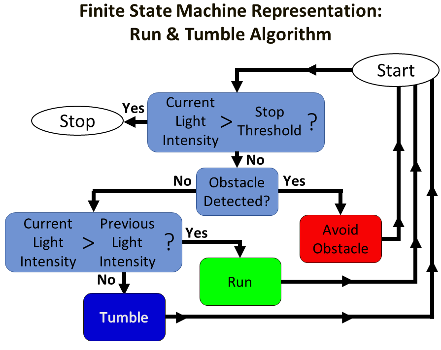
The details of the run-and-tumble algorithm are shown in a finite state machine diagram below. The simple summary is that the Crazyflie takes off, begins moving forward, and if the light intensity is getting larger it continues to “Run” in the same direction. If the light intensity is getting smaller, it will “Tumble” to a random direction. Additional layers of decision making are included to determine if the Crazyflie must “Avoid Obstacle”, or if the source has been reached and the Crazyflie quadcopter should “Stop”.
The run-and-tumble algorithm represented as a finite state machine.
Crazyflie Hardware
To implement the run-and-tumble algorithm autonomously on the Crazyflie, we needed a Crazyflie quadcopter and these additional sensors:
Bitcraze Prototype deck with BH-1750 light intensity sensor
The Optic Flow deck was a key sensor in achieving autonomous flight. This sensor package determines the Crazyflie’s height above the surface and tracks its horizontal motion from the starting position along the x-direction and y-direction coordinates. With the Optic Flow installed, the Crazyflie is capable of autonomously maintaining a constant height above the surface. It can also move forward, back, left, and right a set distance or at a set speed. Several other pre-programmed movement behaviors can also be chosen. This Bitcraze blog post has more information on how the Flow deck works and this post by Chuan-en Lin on Nanonets.com provides more in-depth information if you would like to read more.
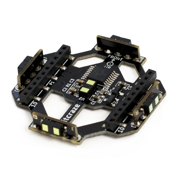
The Bitcraze Multi-ranger deck provided the sensor data for obstacle avoidance. The Multi-ranger detects the distance from the Crazyflie to the nearest object in five directions: forward, backward, right, left, and above. Our threshold to trigger the “Avoid Obstacle” behavior is detecting an obstacle within 0.5 meters of the Crazyflie quadcopter.
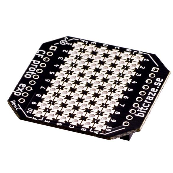
The Prototype deck was a quick, simple way to connect the BH-1750 light intensity sensor to the pins of the Crazyflie to physically integrate the sensor with the quadcopter hardware. This diagram shows how the header positions connect to the rows of pads in the center of the deck. We soldered a header into the center of the deck, then soldered connections between the pads to form continuous connections from our header pin to the correct Crazyflie header pin on the left or right edges of the Prototype deck. The Bitcraze Wiki provides a pin map for the Crazyflie quadcopter and information about the power supply pins. A nice overview of the BH-1750 sensor is found on Components101.com, this shows the pin map and the 4.7 kOhm pull-up resistor that needs to be placed on the I2C line.
It was easy to connect the decks to the Crazyflie because Bitcraze clearly marks “Front”, “Up” and “Down” to help you orient each deck relative to the Crazyflie. See the Bitcraze documentation on expansion decks for more details. Once the decks are properly attached, the Crazyflie can automatically detect that the Flow and Multi-Ranger decks are installed, and all of the built-in functions related to these decks are immediately available for use without reflashing the Crazyflie with updated firmware. (We appreciated this awesome feature!)
Crazyflie Firmware and ROS Control Software
Bitcraze provides a downloadable virtual machine (VM) to help users quickly start developing their own code for the Crazyflie. Our team used a VM that was modified by UW graduate students Melanie Anderson and Joseph Sullivan to make it easier to write ROS control code in the Python coding language to control one or more Crazyflie quadcopters. This was helpful to our team because we were all familiar with Python from previous work. The standard Bitcraze VM is available on Bitcraze’s Github page. The Modified VM constructed by Joseph and Melanie is available through Melanie’s Github page. Available on Joseph’s Github page is the “rospy_crazyflie” code that can be combined with existing installs of ROS and Bitcraze’s Python API if users do not want to use the VM options.
“crazyflie-firmware” – a set of files written in C that can be uploaded to the Crazyflie quadcopter to overwrite the default firmware
In the Bitcraze VM, this folder is located at “/home/bitcraze/projects/crazyflie-firmware”
In the Modified VM, this folder is located at “Home/crazyflie-firmware”
“crazyflie-lib-python” (in the Bitcraze VM) or “rospy_crazyflie” (in the Modified VM) – a set of ROS files that allows high-level control of the quadcopter’s actions
In the Bitcraze VM, “crazyflie-lib-python” is located at “/home/bitcraze/projects/crazyflie-lib-python”
In the Modified VM, navigate to “Home/catkin_ws/src” which contains two main sets of files:
“Home/catkin_ws/src/crazyflie-lib-python” – a copy of the Bitcraze “crazyflie-lib-python”
“Home/catkin_ws/src/rospy_crazyflie” – the modified version of “crazyflie-lib-python” that includes additional ROS and Python functionality, and example scripts created by Joseph and Melanie
In the Modified VM, we edited the “crazyflie-firmware” files to include code for our light intensity sensor, and we edited “rospy-crazyflie” to add functions to the ROS software that runs on the Crazyflie. Having the VM environment saved our team a huge amount of time and frustration – we did not have to download a basic virtual machine, then update software versions, find libraries, and track down fixes for incompatible software. We could just start writing new code for the Crazyflie.
The Modified VM for the Crazyflie takes advantage of the Robot Operating System (ROS) architecture. The example script provided within the Modified VM helped us quickly become familiar with basic ROS concepts like nodes, topics, message types, publishing, and subscribing. We were able to understand and write our own nodes that published information to different topics and write nodes that subscribed to the topics to receive and use the information to control the Crazyflie.
A major challenge of our project was writing a new driver that could be added to the Crazyflie firmware to tell the Crazyflie system that we had connected an additional sensor to the Crazyflie’s I2C bus. Our team referenced open-source Arduino drivers to understand how the BH-1750 connects to an Arduino I2C bus. We also looked at the open-source drivers written by Bitcraze for the Multi-ranger deck to see how it connects to the Crazyflie I2C bus. By looking at all of these open-source examples and studying how to use I2C communication protocols, our team member Nishant Elkunchwar was able to write a driver that allowed the Crazyflie to recognize the BH-1750 signal and convert it to a sensor value to be used within the Crazyflie’s ROS-based operating system. That driver is available on Nishant’s Github. The driver needed to be placed into the appropriate folder: “…\crazyflie-firmware\src\deck\drivers\src”.
The second change to the crazyflie-firmware is to add a “config.mk” file in the folder “…\crazyflie-firmware\tools\make”. Information about the “config.mk” file is available in the Bitcraze documentation on configuring the build.
The final change to the crazyflie-firmware is to update the make file “MakeFile” in the location “…\crazyflie-firmware”. The “MakeFile” changes include adding one line to the section “# Deck API” and two lines to the section “# Decks”. Information about compiling the MakeFile is available in the Bitcraze documentation about flashing the quadcopter.
Making additions to the ROS control architecture
The ROS control architecture includes messages. We needed to define 3 new types of messages for our new ROS control files. In the folder “…\catkin_ws\src\rospy_crazyflie\msg\msg” we added one file for each new message type. We also updated “CMakeLists.txt” to add the name of our message files in the section “add_message_files( )”.
The second part of our ROS control was a set of scripts written in Python. These included our run-and-tumble algorithm control code, publisher scripts, and a plotter script. These are all available in the project’s Github.
Characterizing the Light Sensor
At this point, the light intensity sensor was successfully integrated into the Crazyflie quadcopter. The new code was written and the Crazyflie quadcopter was reflashed with new firmware. We had completed our initial trouble shooting and the next step was to characterize the light intensity in our experimental setup.
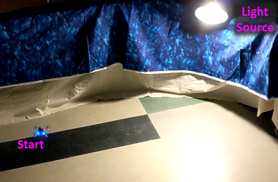
Experimental setup for light intensity characterization.
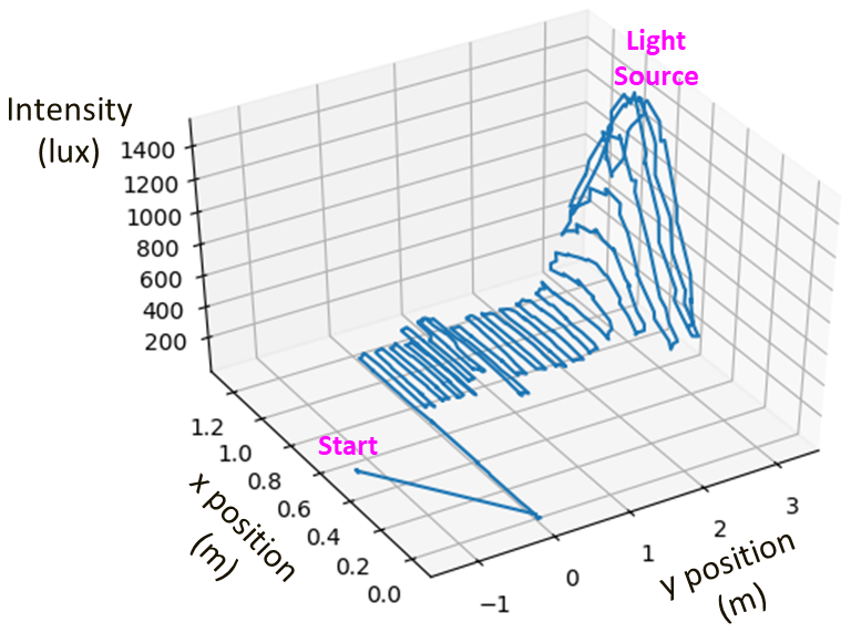
This characterization was done by flying the Crazyflie at a fixed distance above the floor in tightly spaced rows along the x and y horizontal directions. The resulting plot (below) shows that the light intensity increases exponentially as the Crazyflie moves towards the light source.
The light characterization allowed us to determine an intensity threshold that will only happen near the light source. If this threshold is met, the algorithm’s “Stop” action is triggered, and the Crazyflie lands.
Light intensity (units of lux) was experimentally characterized by piloting the Crazyflie in a linear pattern at a constant height above the ground. The resulting plot shows that light intensity is characterized by an exponential roll off in both the x and y directions.
Testing the Run-and-Tumble Algorithm
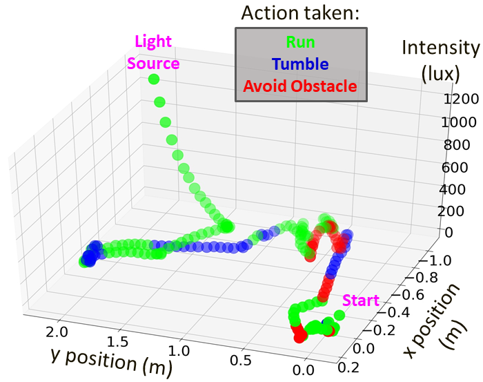
With the light intensity characterization complete, we were able to test and revise our run-and-tumble algorithm. At each loop of the algorithm, one of the four actions is chosen: “Run”, “Tumble”, “Avoid Obstacle”, or “Stop”. The plot below shows a typical path with the action that was taken at each loop iteration.
Flight Tests of the Run-and-Tumble Algorithm
In final testing, we performed 4 trial runs with 100% success locating the light source. Our test area was approximately 100 square feet, included 1 light source, and 2 obstacles. The average search time was 1:41 seconds.
The “Avoid Obstacle” and “Run” behavior are demonstrated in the above video clip (1.5x actual speed).
The “Run” and “Tumble” actions are demonstrated in the above video clip (2x actual speed). At the end, the “Stop” action is demonstrated when the light intensity reaches the threshold value of 800 lux, indicating that the Crazyflie has found the light source and should land.
Lessons Learned
This was one of the best courses I’ve taken at the University of Washington. It was one of the first classes where a robot could be incorporated, and playing with the Crazyflie was pure fun. Another positive aspect was that the course had the feel of a boot camp for learning how to build, control, test, and improve autonomous robots. This was only possible because Bitcraze’s small, indoor quadcopter with optic flow capability made it possible to safely operate several quadcopters simultaneously in our small classroom as we learned.
This development project was really interesting (aka difficult…) and we went down a few rabbit holes as we tried to level up our knowledge and skills. Our prior experience with Python helped us read the custom example scripts provided in our course for the ROS control program, but we had quite a bit to learn about the ROS architecture before we could write our own control scripts.
Nishant made an extensive study of I2C protocols as he wrote the new driver for the BH-1750 sensor. One of the biggest lessons I learned in this project was that writing drivers to integrate a sensor to a microcontroller is hard. By contrast, using the Bitcraze decks was so easy it almost felt like cheating. (In the nicest way!)
On the hardware side, the one big problem we encountered during development was accidentally breaking the 0.5 mm headers on the Crazyflie quadcopter and the decks. The male headers were not long enough to extend from the Flow deck all the way up through the Prototype deck at the top, so we tried to solder extensions onto the pins. Unfortunately, I did not check the Bitcraze pin width and I just soldered on the pins we all had in our tool kits: the 0.1 inch (2.54 mm) wide pins that we use with our Arduinos and BeagleBones. These too-large-pins damaged the female headers on the decks, and we lost connectivity on those pins. Fortunately, we were able to repair our decks by soldering on replacement female headers from the Bitcraze store. I wish now that the long pin headers were available back then.
In summary, this course was an inspiring experience and helped our team learn a lot in a very short time. After ten weeks working with the Crazyflie, I can strongly recommend the Crazyflie for robotics classes and boot camps.