Loco positioning system is still in Early access which means that things are moving fast. Since the release of the loco positioning system a Kalman filter has been contributed by Mike Hammer at ETH Zurich. The Kalman filter allows to calculate the position estimate in the Crazyflie and merges the Loco positioning system information with internal sensor to generate a much better estimate. We also worked on improving the anchor firmware, it is now ranging faster and we fixed a bug that was making the anchor hang sometime. Finally stephanbro on github pushed an improved position controller that improved the stability of flight a lot.
Because of all these changes we have decided to make a new video and to rewrite the documentation on the wiki a bit. Enjoy!
On the development side, we have extended the Loco Positioning system to position 2 concurrent Tags by using TDMA (Time Division Multiple Access) where each Tag is allocated a time slot to use to range to the anchors.
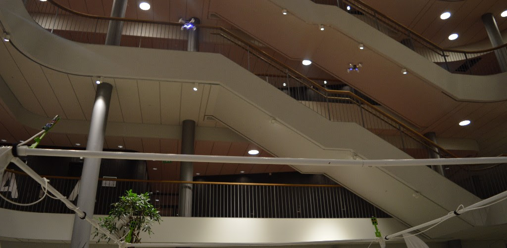
This works fine for a few Tags, but does not scale very well for a larger numbers of tags. If you want to experiment by yourself there is some instruction in the git commit. Be aware that this is still experimental enough for us to break it without warning so keep track of the git commits when you pull the latest version of the firmware. Currently we are working on a TDoA (Time Difference Of Arrival) mode that will scale to concurrently position virtually an infinite number of tags, hopefully you will soon be able to see commits on that on our Github projects.