The Lighthouse V2 implementation has been simmering away for a long time in the Bitcraze kitchen and in this blog post we will give you an update on the current status and what is remaining for a full release of this tasty dish.
We believe we have solved most of the major technical hurdles (last famous words) on the way to a working implementation that uses Lighthouse V2 base stations for positioning, now it is mostly work to implement the functionality that is remaining. As described in this post we now have a new FPGA binary that has the ability to decode both V1 and V2 base stations, and this was a major step forward. This new binary is used in the Crazyflie firmware master branch, and if the Lighthouse deck is used with the latest Crazyflie firmware, the new FPGA binary will automatically be flashed to the deck.
What has changed?
The new FPGA binary uses a different UART protocol to communicate with the Crazyflie. This protocol has been implemented in the firmware and hopefully there is no functional difference compared to the previous FPGA binary when using Lighthouse V1 base stations.
We have added a first version of Lighthouse V2 base station decoding, but it is still a bit limited. As a start we decided to “emulate” V1 base stations to be able to reuse as much of the existing code as possible. For now we support only 2 base stations and they must use channel 1 and 2 (used to be called modes). The V2 angles are transformed into V1 angles and fed into the old positioning logic and are handled exactly the same way as before. Even though this works, it is not the optimal solution and we hope to be able to refine it later on.
We have also written a python script to estimate base station geometry (positions and orientation) using the Lighthouse deck. This removed the requirement to use software from Steam which should simplify the set up process. Please see the (still limited) documentation. Note that this calibration method only supports the basestation V1… for now!
There is a lot of code that has been modified and the FPGA implementation is completely new, it is not unlikely that there is functionality that is unstable or broken, or configurations that are not supported. If you happen to notice any bugs, please let us know!
What is remaining?
The functional areas that needs to be implemented or cleaned up before we leave the Early Access stage is the following:
Calibration data
The calibration data is embedded in the modulated light from the base stations and describes imperfections from the manufacturing process for each individual. This data is not read yet for V2 and will increase the precision when available.
Support for more than 2 base stations
Lighthouse V2 base stations are designed for systems with more than 2 base stations. The Crazyflie firmware needs to be extended for this functionality to work, including handling of geometry data, logging, memory management and some other bits and pieces.
Native V2 positioning
The angles from the V2 base station should be fed directly into the kalman filter for positioning, instead of first being transformed into V1 angles. This will increase robustness and reduce data loss.
Client support
We want to add a tab in the python client where a Lighthouse system can be monitored, configured and managed. It should, for instance enable the user to configure and visualize base station geometry.
FPGA binaray management
Currently the FPGA binary is included in the Crazyflie firmware and it is automatically uploaded to the deck when booted. This is not a viable long term solution and we hope to be able to find a more generic way of handling deck binaries.
Conclusions
As can be seen, there is still quite some work to be done before the Lighthouse V2 stew is ready to be served, but we are definitely starting to smell some nice flavours from the kitchen!
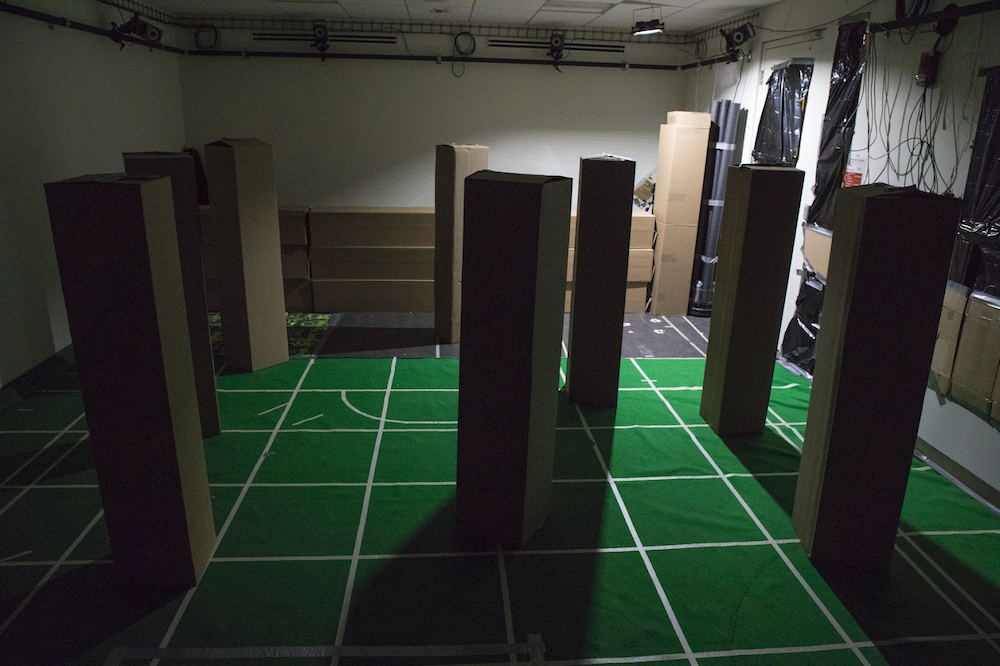
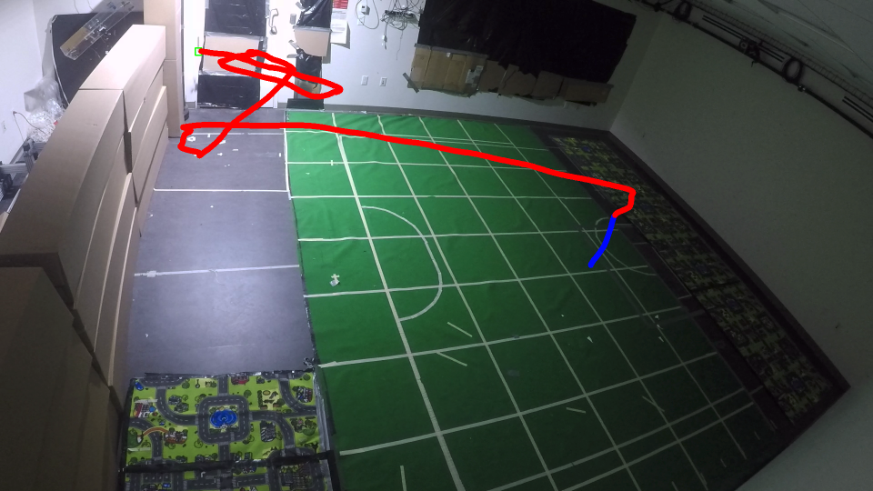
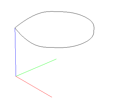
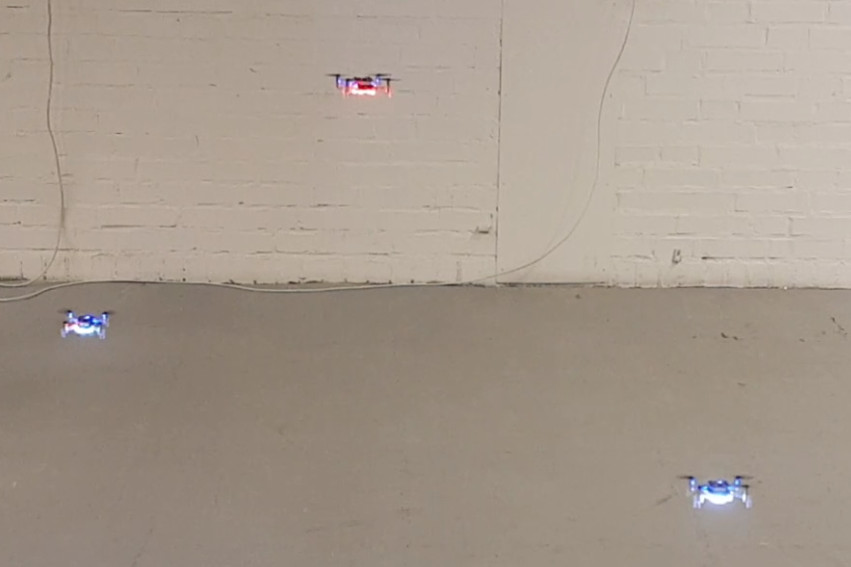
Finally a view from Kristoffer’s home lab, currently in the summer house. Three base stations are set up as a Fun Friday hack to see what it would take to use more than 2. Luckily it did not take too much time to get this to work :-)