This autumn when we had our quarterly planing meeting, it was obvious that there would not be any conferences this year like other years. This meant we would not meet you, our users and hear about your interesting projects, but also that we would not be forced to create a demo. Sometimes we joke that we are working with Demo Driven Development and that is what is pushing us forward, even-though it is not completely true it is a strong driver. We decided to create a demo in our office and share it online instead, we hope you enjoy it!
The wish list for the demo was long but we decided that we wanted to use multiple positioning technologies, multiple platforms and multiple drones in a swarm. The idea was also to let the needs of the demo drive development of other technologies as well as stabilize existing functionality by “eating our own dogfood”. As a result of the work we have for instance:
- improved the app layer in the Crazyflie
- Lighthouse V2 support, including basic support for 2+ base stations
- better support for mixed positioning systems
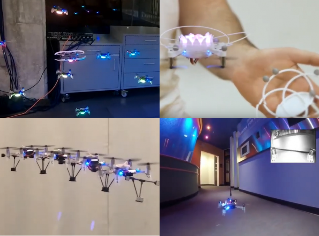
First of all, let’s check out the video
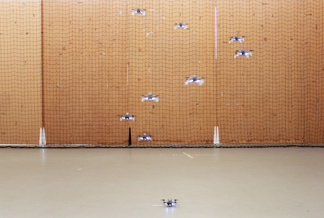
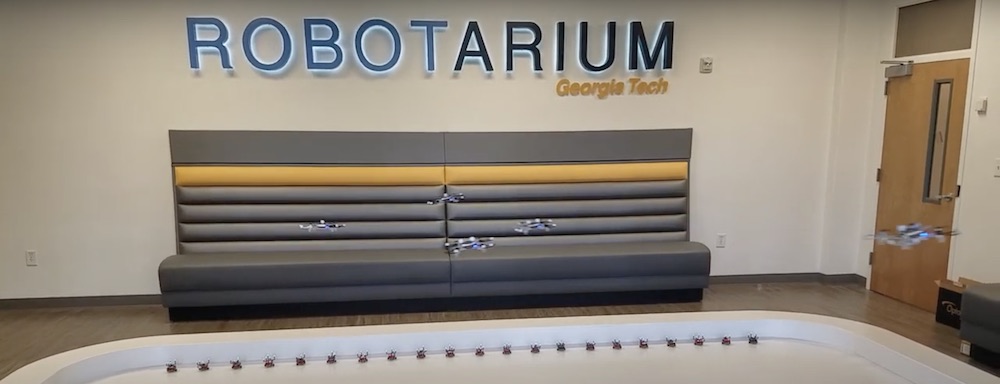
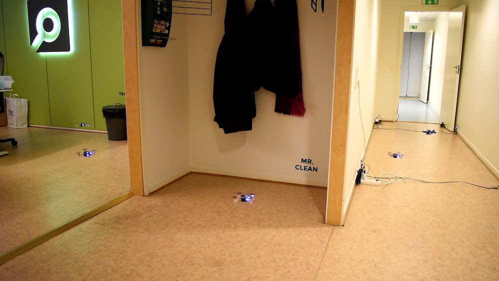
We are using our office for the demo and the Crazyflies are essentially flying a fixed trajectory from our meeting room, through the office and kitchen to finally land in the Arena. The Crazyflies are autonomous from the moment they take off and there is no communication with any external computer after that, all positioning is done on-board.
Implementation
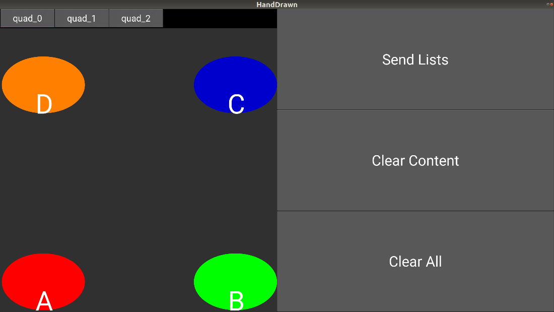
The demo is mainly implemented in the Crazyflie as an app with a simple python script on an external machine to start it all. The app is identical in all the Crazyflies so the script tells them where to land and checks that all Crazyflies has found their position before they are started. Finally it tells them to take off one by one with a fixed delay in-between.
The Crazyflie app
When the Crazyflie boots up, the app is started and the first thing it does is to prepare by defining a trajectory in the High Level Commander as well as setting data for the Lighthouse base stations in the system. The app uses a couple of parameters for communication and at this point it is waiting for one of the parameters to be set by the python script.
When the parameter is set, the app uses the High Level Commander to take off and fly to the start point of the trajectory. At the starting point, it kicks off the trajectory and while the High Level Commander handles the flying, the app goes to sleep. When reaching the end of the trajectory, the app once more goes into action and directs the Crazyflie to land at a position set through parameters during the initialization phase.
We used a feature of the High Level Commander that is maybe not that well known but can be very useful to make the motion fluid. When the High Level Commander does a go_to for instance, it plans a trajectory from its current position/velocity/acceleration to the target position in one smooth motion. This can be used when transitioning from a go_to into a trajectory (or from go_to to go_to) by starting the trajectory a little bit too early and thus never stop at the end of the go_to, but “slide” directly into the trajectory. The same technique is used at the end of the trajectory to get out of the way faster to avoid being hit by the next Crazyflie in the swarm.
The trajectory
The main part of the flight is one trajectory handled by the High Level Commander. It is generated using the uav_trajectories project from whoenig. We defined a number of points we wanted the trajectory to pass through and the software generates a list of polynomials that can be used by the High Level Commander. The generated trajectory is passing through the points but as a part of the optimization process it also chooses some (unexpected) curves, but that could be fixed with some tweaking.
The trajectory is defined using absolute positions in a global coordinate system that spans the office.
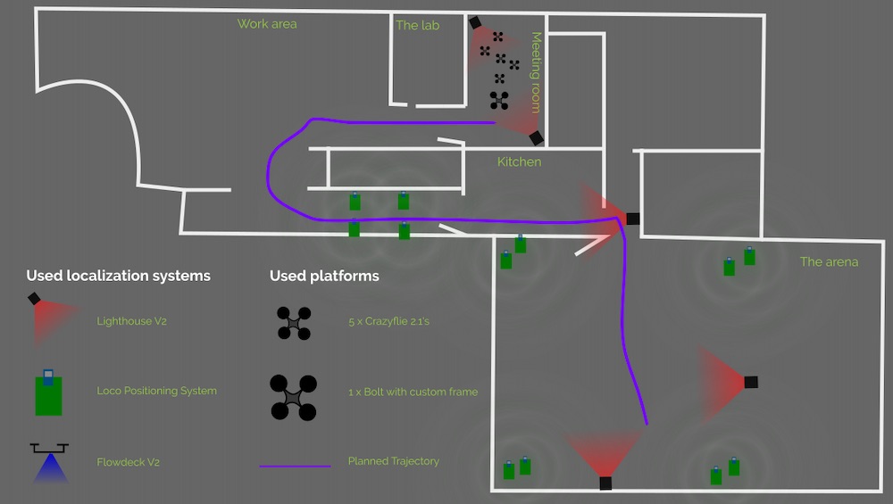
Positioning
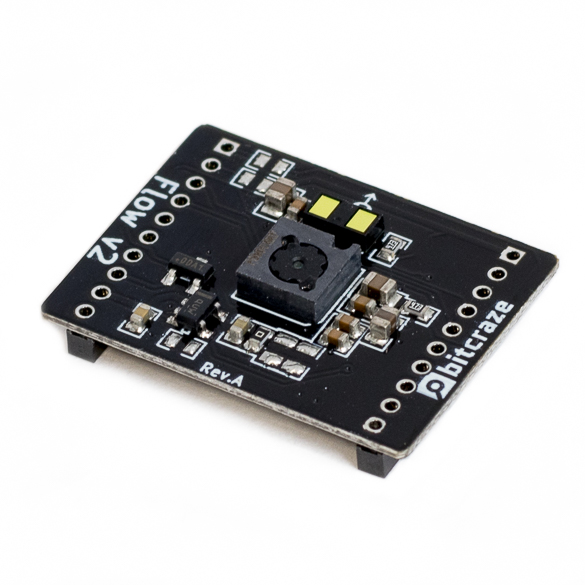
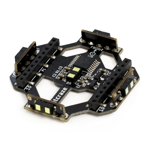
We used three different positioning systems for the demo: the Lighthouse (V2), the Loco Positioning system (TDoA3) and the Flow deck. Different areas of the flight space is covered by different system, either individually or overlapping. All decks are active all the time and pick up data when it is available, pushing it into the extended Kalman estimator.
In the meeting room, where we started, we used two Lighthouse V2 base stations which gave us a very precise position estimate (including yaw) and a good start. When the Crazyflies moved out into the office, they only relied on the Flowdeck and that worked fine even-though the errors potentially builds up over time.
When the Crazyflies turned around the corner into the hallway towards the kitchen, we saw that the errors some times were too large, either the position or yaw was off which caused the Crazyflies to hit a wall. To fix that, we added 4 LPS nodes in the hallway and this solved the problem. Note that all the 4 anchors are on the ground and that it is not enough to give the Crazyflie a good 3D position, but the distance sensor on the Flow deck provides Z-information and the overall result is good.
The corner when going from the kitchen into the Arena is pretty tight and again the build up of errors made it problematic to rely on the Flow deck only, so we added a lighthouse base station for extra help.
Finally, in the first part of the Arena, the LPS system has full 3D coverage and together with the Flow deck it is smooth sailing. About half way the Crazyflies started to pick up the Lighthouse system as well and we are now using data from all three systems at the same time.
Obviously we were using more than 2 basestations with the Lighthouse system and even though it is not officially supported, it worked with some care and manual labor. The geometry data was for instance manually tweaked to fit the global coordinate system.
The wall between the kitchen and the Arena is very thick and it is unlikely that UWB can go through it, but we still got LPS data from the Arena anchors occasionally. Our interpretation is that it must have been packets bouncing on the walls into the kitchen. The stray packets were picked up by the Crazyflies but since the Lighthouse base station provided a strong information source, the LPS packets did not cause any problems.
Firmware modifications
The firmware is essentially the stock crazyflie-firmware from Github, however we did make a few alterations though:
- The maximum velocity of the PID controller was increased to make it possible to fly a bit faster and create a nicer demo.
- The number of lighthouse base stations was increased
- The PID controller was tweaked for the Bolt
You can find the source code for the demo on github. The important stuff is in examples/demos/hyperdemo
The hardware
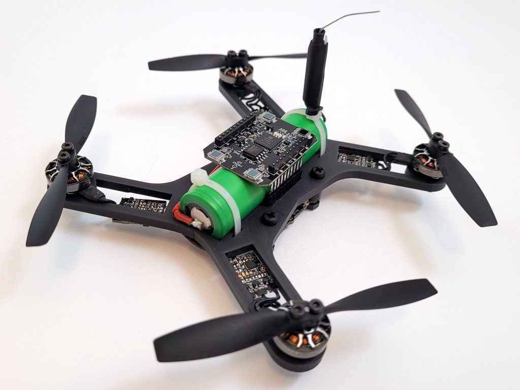
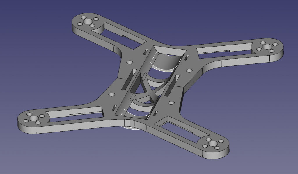
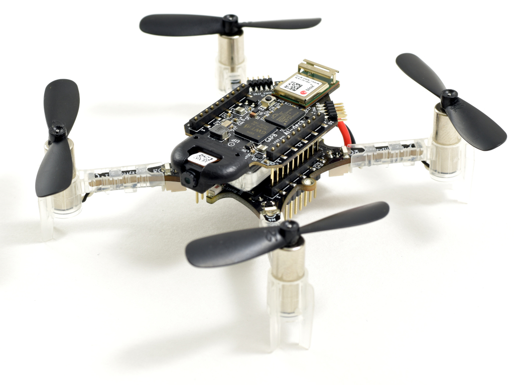
In the demo we used 5 x Crazyflie 2.1 and 1 x Bolt very similar to the Li-Ion Bolt we built recently. The difference is that this version used a 2-cell Li-Po and lower KV motors but the Li-Ion Bolt would have worked just as well.
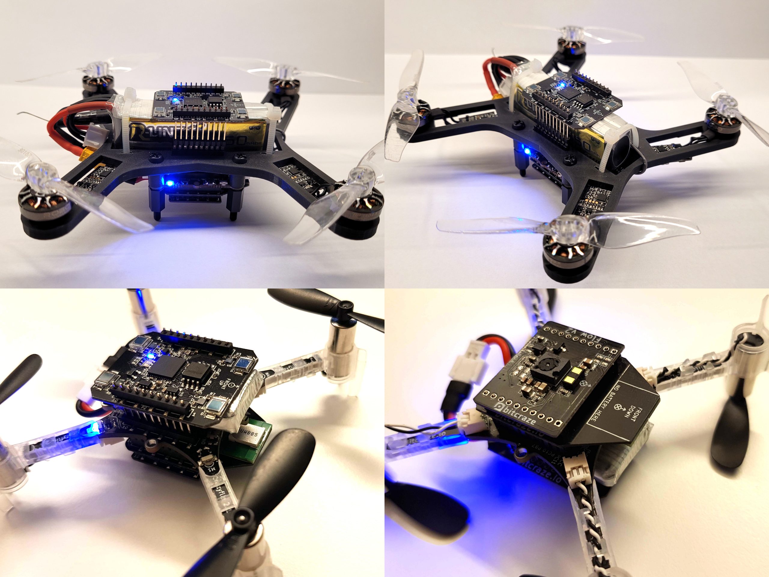
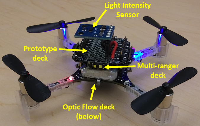
To make all positioning to work at the same time we needed to add 3 decks, Lighthouse, Flow v2 and Loco-deck. On the Crazyflie 2.1 this fits if the extra long pin-headers are used and the Lighthouse is mounted on top and the Loco-deck underneath the Crazyflie 2.1 with the Flow v2 on the bottom. The same goes for the Bolt, but here we had to solder the extra long pin-header and the long pin-header together to make them long enough.
There is one catch though… the pin resources for the decks collide. With some patching of the loco-deck this can be mitigated by moving its IRQ to IO_2 using the solder-jumper. The RST needs to be moved to IO_4 which requires a small patch wire.
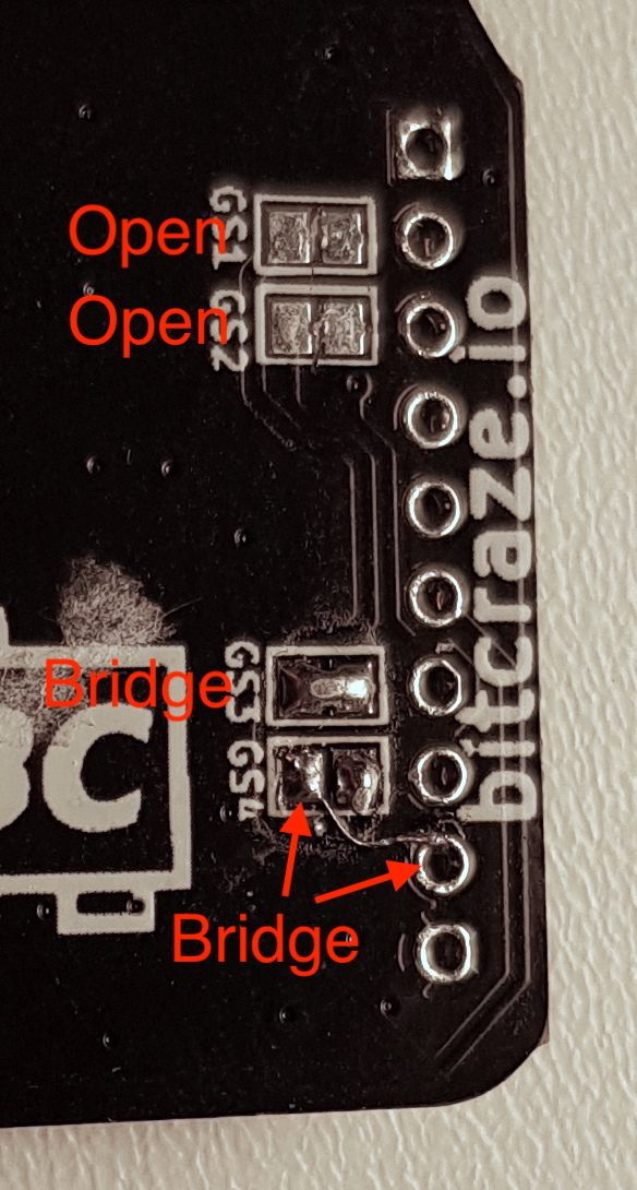
Also some FW configuration is needed which is added to the hyperdemo makefile:
CFLAGS += -DLOCODECK_USE_ALT_PINS
CFLAGS += -DLOCODECK_ALT_PIN_RESET=DECK_GPIO_IO4
The final weight for the Crazyflie 2.1 is on the heavy side and we quickly discover that fully charged batteries should be used or else the crash probability is increased a lot.
Conclusions
We’re happy we were able to set this demo up and that it was fairly straight forward. The whole setup of it was done in one or two days. The App layer is quite useful and we tend to use it quite often when trying out ideas, which we interpret as a good sign :-)
We are satisfied with the results and hope it will inspire some of you out there to push the limits even further!