We have now worked a few weeks on the new TDoA 3 mode for the Loco Positioning System. We are happy with the results so far and think we managed to do what we aimed for: removing the single point of failure in anchor 0 and supporting many anchors as well as larger spaces.
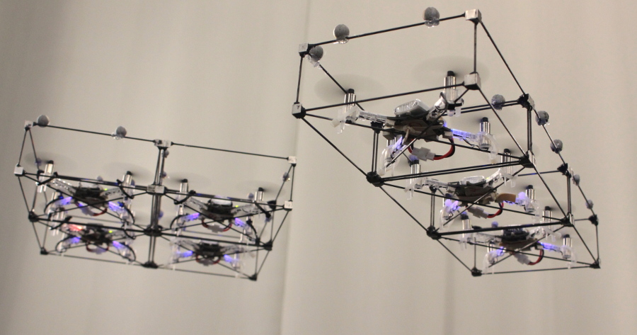
We finished off last week by setting up a system with 20 anchors covering two rooms down in the lunch area of the office. We managed to fly a scripted autonomous flight between two rooms.
Work so far on the anchors
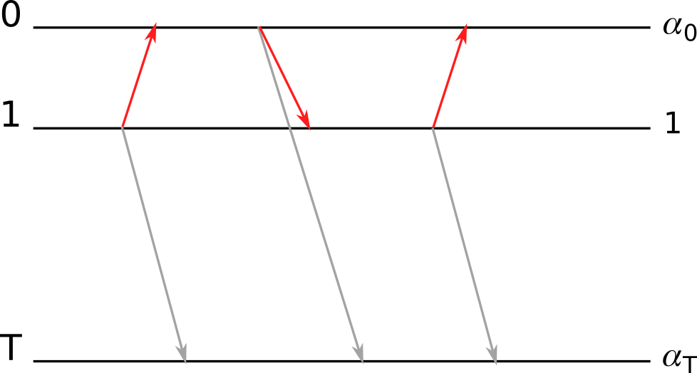
Messages from the anchors are now transmitted at random times, which removes the dependency on anchor 0 that used to act as a master that all other anchors were synchronized to. The drawback is that we get problems with collisions when two anchors happens to transmit at the same time. Experiments showed that at 400 packets/s (system rate) we ended up at a packet loss of around 15% and 340 TDoA measurements/s sent to the kalman filter for position estimation. We figured that this was acceptable level and added an algorithm in the anchors that reduces the transmission rate based on the number of anchors around them. If more anchors are added to a room they all reduce their transmission rate to target 400 packets/s in total system rate.
The anchors continuously keeps track of the clock drift of all other anchors by listening to the messages that are transmitted. We know that clocks do not change frequency suddenly and can use this fact to filter the clock correction to reduce noise in the data. Outliers are detected and removed and the resulting correction is low pass filtered. We have done some experiments on using this information and compare it to the time stamp of a received message to detect if the time stamp is corrupt or not, but this idea requires more work.
One interesting feature of the anchors is the limited CPU power that is available. The strategy we have chosen to handle this fact has been to create an algorithm that is efficient when handling messages. A timer based maintenance algorithm (@1 Hz) examines the received data and makes demissions on which anchors to include in the messages in the future as well as purges old data.
The Crazyflie
The implementation in the Crazyflie is fairly straight forward. The biggest change to TDoA 2 is that we now can handle a dynamic number of anchors and have to chose what data to store and what to discard. We have also extracted the actual TDoA algorithm into a module to separate it from the TDoA 3 protocol. The clock correction filtering algorithm from the anchors has also been implemented in the Crazyflie.
An experimental module test has been added where the TDoA module is built and run on a PC using data recorded from a sniffer. We get repeatability as well as better tools for debugging and this is something that we should explore further.
Work remaining
The estimated position in the Crazyflie is still more noisy than in TDoA 2 and we would like to improve it to at least the same level. We see that we have outliers in the TDoA measurements that makes the Crazyflie go off in a random direction from time to time, we believe it should be possible to get rid of most of these.
The code is fairly hackish and there are no structured unit or module tests to verify functionality. So far the work has been in an exploratory phase but we are getting closer to a set of algorithms that we are happy with and that are worth testing.
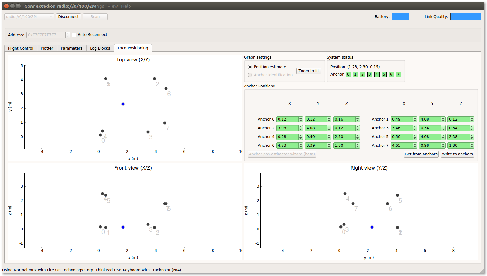
We have not done any work on the client side, that is support for visualizing and configuring the system. This is a substantial amount of work and we will not officially release TDoA 3 until this is finished.
How to try it out
If you are interested in trying TDoA 3 out your self, it is all available on github. There are no hardware changes and if you have a Loco Positioning system it should work just fine. There is a short description on the wiki of how to compile and configure the system. The anchor supports both TDoA 2 and TDoA 3 through configuration while the Crazyflie has to be recompiled to change between the two. The support in the client is limited but will basically handle anchors 0 – 7.
Have fun!