Whether You Realize It or Not, You’re Part of the Crazyflie Community
Most people probably don’t think of themselves as members of the Crazyflie community. They’re busy finishing experiments, writing papers, debugging flight controllers, supervising students, preparing grant applications, or trying to make a deadline. And yet, whether you think about it or not, you’re part of it.
Every time a paper is published, a GitHub issue is filed, a forum question is answered, or a new experiment is shared, the platform changes a little. Other researchers discover new approaches. Students inherit new examples. Future users benefit from lessons that someone else learned the hard way.
The Crazyflie ecosystem is not defined by Bitcraze. It is defined by thousands of individual decisions made across universities, research institutes, classrooms, and laboratories around the world, which makes us curious:
What are you working on?
What tools do you rely on?
What parts of the ecosystem help you move faster, and which parts slow you down?
What should we spend more time improving?
To help answer those questions, we’re running a community survey. Not because we need validation for decisions we’ve already made, but because many of the decisions we will make next should be informed by the people who use the platform every day.
If you use the Crazyflie, your experience matters. Make your voice heard!
Some Fun-Friday projects begin with a clear goal and a straight path to the finish line. The best ones, however, take you somewhere completely unexpected.
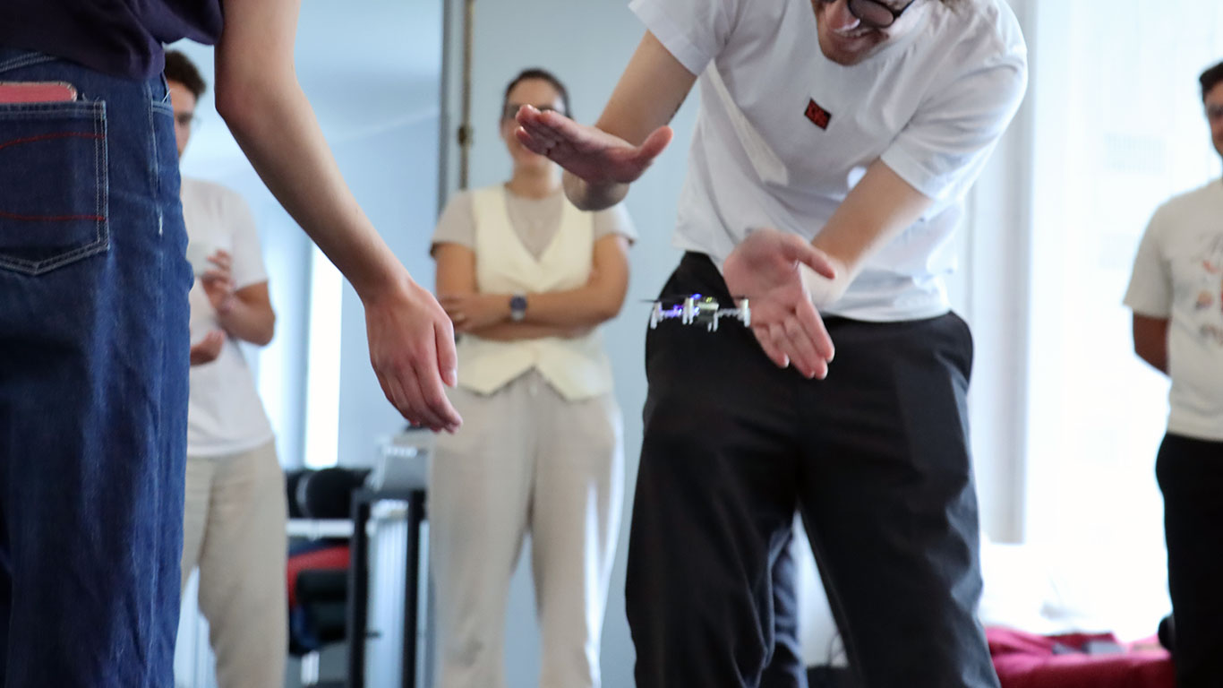
This project originally set out to build a device for determining spatial coordinates within a Lighthouse-covered flight area. Instead, it evolved into the Lighthouse Wand, a hand-held “magic wand” letting you grab and move drones in 3D space just by pointing at them.
How it works
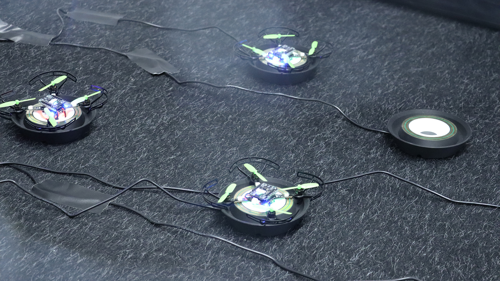
The Wand is a Crazyflie platform with a Lighthouse positioning deck. That’s enough for it to know its own position and orientation in the room. When the button is pressed, it starts broadcasting those 6 numbers over Peer to Peer radio.
Any Crazyflie/receiver in the room on the same radio channel, listens to those packets and runs a simple “grasping” algorithm: while the wand line (positive x-axis) passes close enough to the drone, it builds up a confidence score. Once the score crosses a threshold, the drone is considered grasped. From that point on, it just keeps a specific distance from the wand, while being on the wand line.
When the button is released, the grasped drone either hovers in place, or lands, depending on the release height.
The Color LED deck on the receiver drone, gives you visual feedback: yellow while the Crazyflie is building up its confidence score, green when it’s grasped, and red when it’s landing.
A big advantage of this system is that all interactions run entirely onboard the Crazyflies, allowing them to operate without relying on the cfclient or cflib during flight.
The hardware design
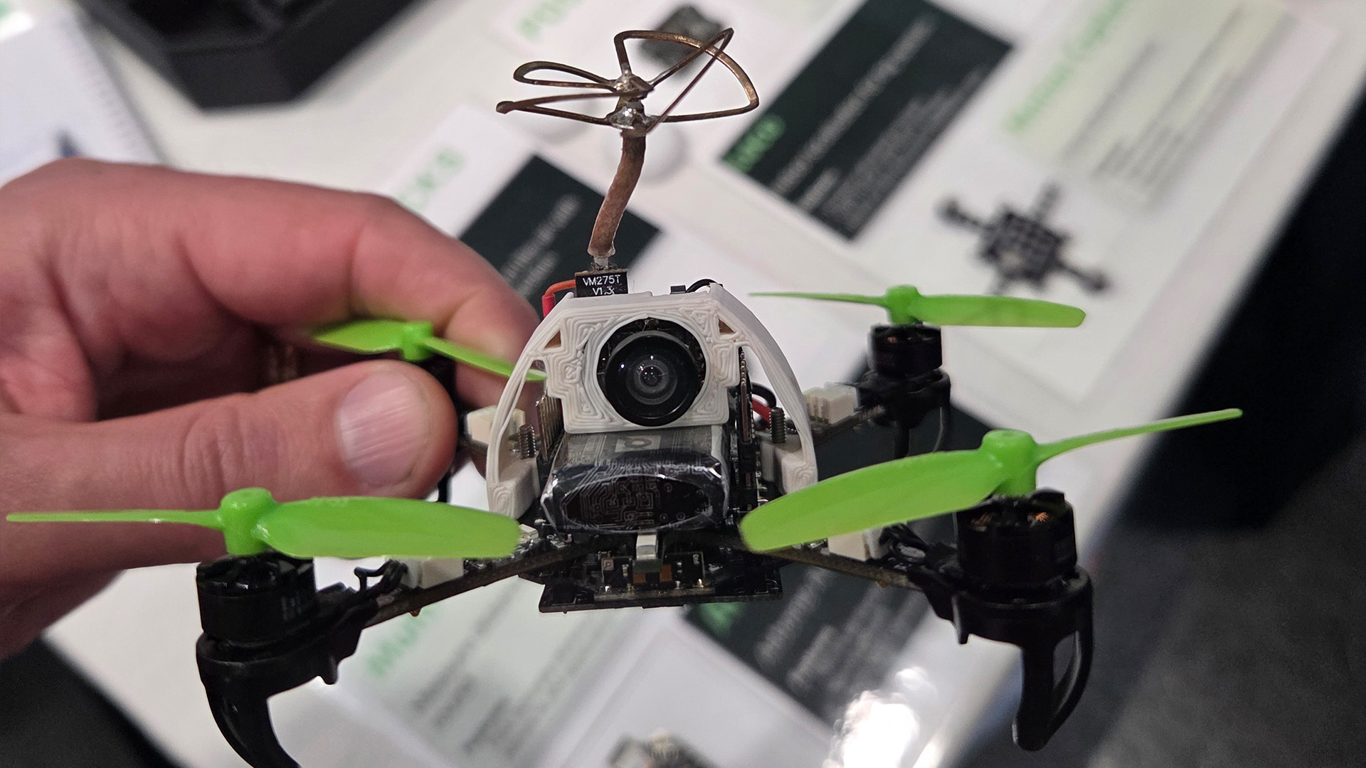
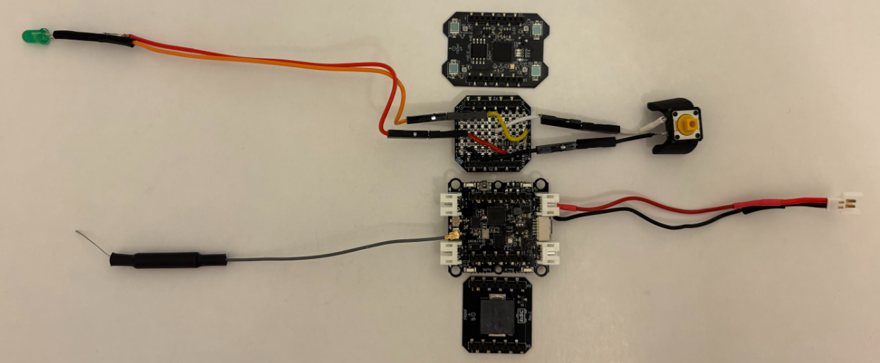
The wand is a Crazyflie Bolt 1.1 with a Lighthouse positioning deck and a Buzzer deck for audio feedback. To allow for user input, I created a simple “Button deck” based on the Prototyping deck utilizing the GPIO pins of the Crazyflie. It also includes an LED for visual feedback when the button is pressed.
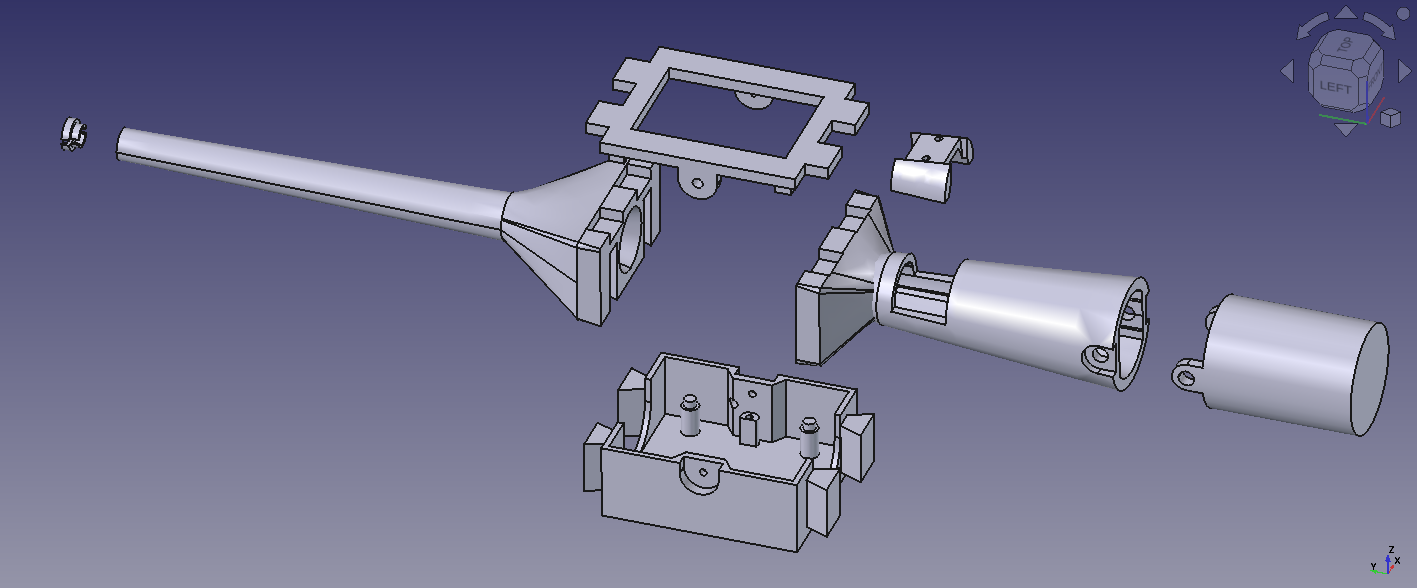
The casing is fully 3D printed in PLA and was designed to give the device a more wand-like feel in the hand. Its shape also makes it easier to hold, aim, and use intuitively during interaction.
The firmware design
Both the Wand and the receiver are firmware apps created on top of the crazyflie-firmware. In the design that I followed, there is a clean separation between the two parties. The wand is a pure broadcaster: it only reads its own pose and transmits it. All grasping logic and flight control run independently on each receiver. Since each receiver is fully autonomous, the system scales to any number of drones with no extra load on the wand.
Where to find the Lighthouse Wand?
A version of the Lighthouse wand is now integrated in our decentralized swarm demo, where it can be used to interact with multiple drones, while the collision avoidance algorithms are still on. This system was first showcased at the European Robotics Forum 2026 in Stavanger, and we’ll also be bringing it to ICRA 2026. If you’re there, stop by booth 91and try flying a bunch of Crazyflies yourself using the wand.
You can find the complete Lighthouse Wand project in this repository. It contains the firmware, the hardware files, and detailed documentation to build and experiment with the wand yourself.
If you’ve ever gone looking for a more advanced, or use-case-specific Crazyflie example (something beyond the basic single-feature ones), you’ve probably ended up digging through the cflib and crazyflie-firmware example folders. That’s about to change.
We’ve created a new repository: crazyflie-demos. It’s a dedicated place where both us at Bitcraze and the broader community can host self-contained, well-described Crazyflie demos.
Why a new repository?
The examples in the core Bitcraze repositories were meant to be kept focused: demonstrating one feature, one API, or one subsystem at a time. But real demos tend to grow beyond that pretty quickly. Once you start combining positioning systems, swarming, custom firmware apps, external sensors, or other integrations, things stop fitting naturally into the firmware or library repos.
crazyflie-demos gives those larger, more practical examples a proper home, and finally provides a good answer to the question: “where should I put this cool thing I built?”
Why not just a folder of examples?
We want to avoid the fate of some older example collections that gradually turned into an unmaintained pile of half-working demos and missing context.
The goal with crazyflie-demos is that every demo should be properly documented and actually runnable. That means clear descriptions, listed dependencies, and enough context to understand what’s going on without digging through source code for an hour.
Another important part is reproducibility: each demo is self-contained and uses pinned dependencies, so an example you clone two years from now should still work.
What’s in there already?
The repository is organized by demo type:
scripts/cflib: Host-side Python scripts using crazyflie-lib-python, covering the full Crazyflie API.
scripts/rust: Rust demos using crazyflie-lib-rs, showcasing its high-performance and native async support.
scripts/cflib2: Early demos for our new Python library, crazyflie-lib-python-v2, built on top of the Rust library. cflib2 doesn’t have a release yet, but we’re already writing demos for it to test the API and the performance.
firmware: Out-of-tree firmware apps that are flashed directly to the Crazyflie. Each demo carries its own crazyflie-firmware submodule so you’re always building against the right version.
hybrid: Demos that combine onboard firmware with a host-side script working together.
A place to share your work
A big motivation behind crazyflie-demos is making it easier to share work with the community.
If you’ve built something useful, or just a fun experiment using our products, this is the place for it. Not everything needs to live in its own repository or branch. A well-described demo here makes it easier for others to find, understand, and build on your work, and most importantly, to get inspired by it.
We’ll also be using this repository as the go-to reference whenever people ask for more use-case-specific examples, so good demos here will naturally help more people discover what’s possible with the Crazyflie ecosystem.
We are constantly amazed about what awesome things you, our users, do with our products, and how well you do it. Time and time again you push the limits of what the Crazyflie can do, and what is possible within the field of robotics. We do what we can to provide the best possible foundation for all your visions, both in terms of improvements to existing features and also adding new, awesome features. Once in a while, though, you find something that you think can be improved, that we have not thought about, and you know how it can be solved. This is what this blog post is about – how to take an idea that you have and make it available to all of our users…
First, let’s just clarify that we are talking about software today. There is hardware and mechanics as well, but let’s save that for another time. Our software is open source. Being open source is one of the foundational pillars that we at Bitcraze build upon. We believe that this a great way for you to understand our products; everyone has the possibility to understand and troubleshoot the Bitcraze products. It also makes it easier for us to collaborate with all of you and in the end makes for better products for all of you. A positive spiral of enabling awesomeness.
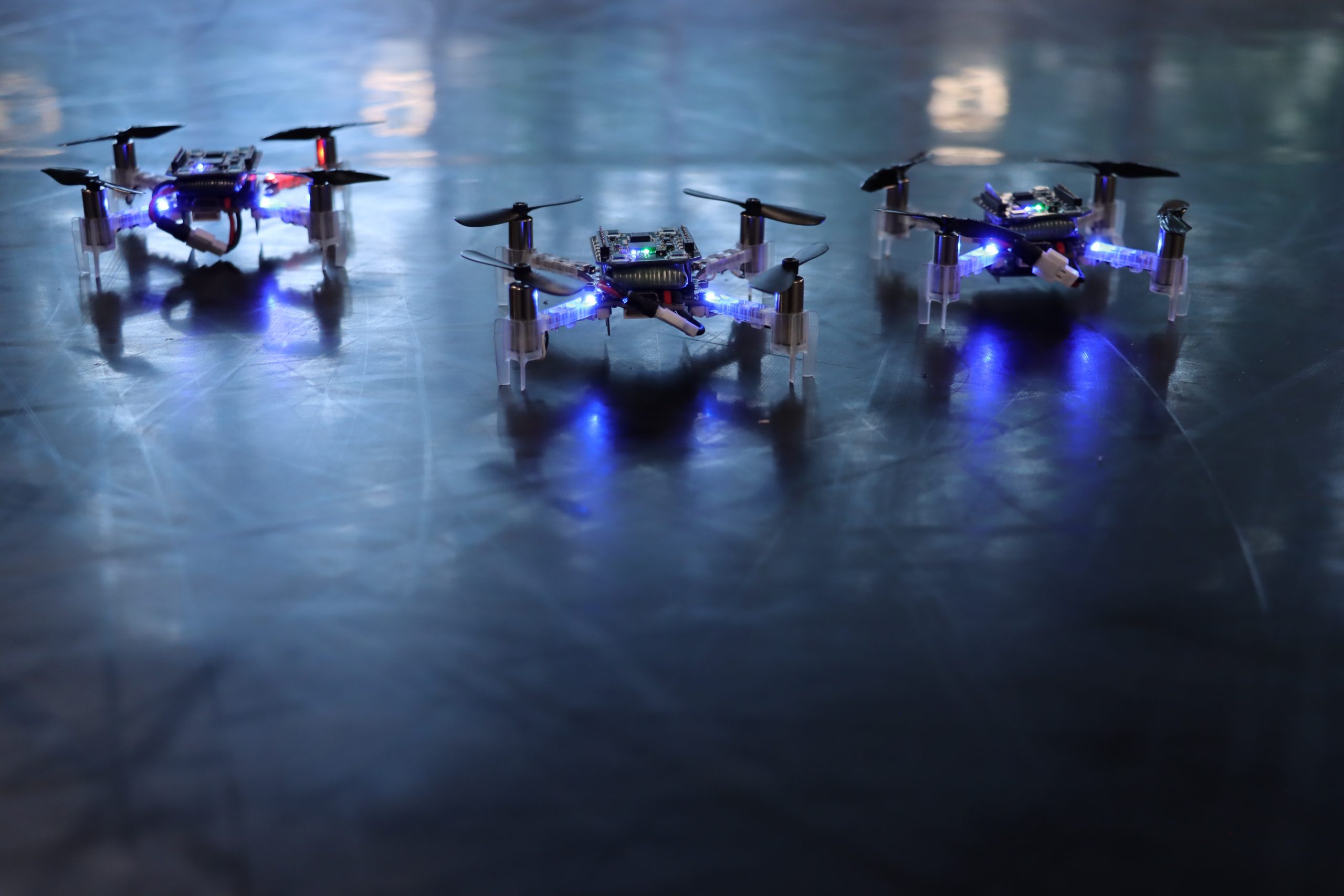
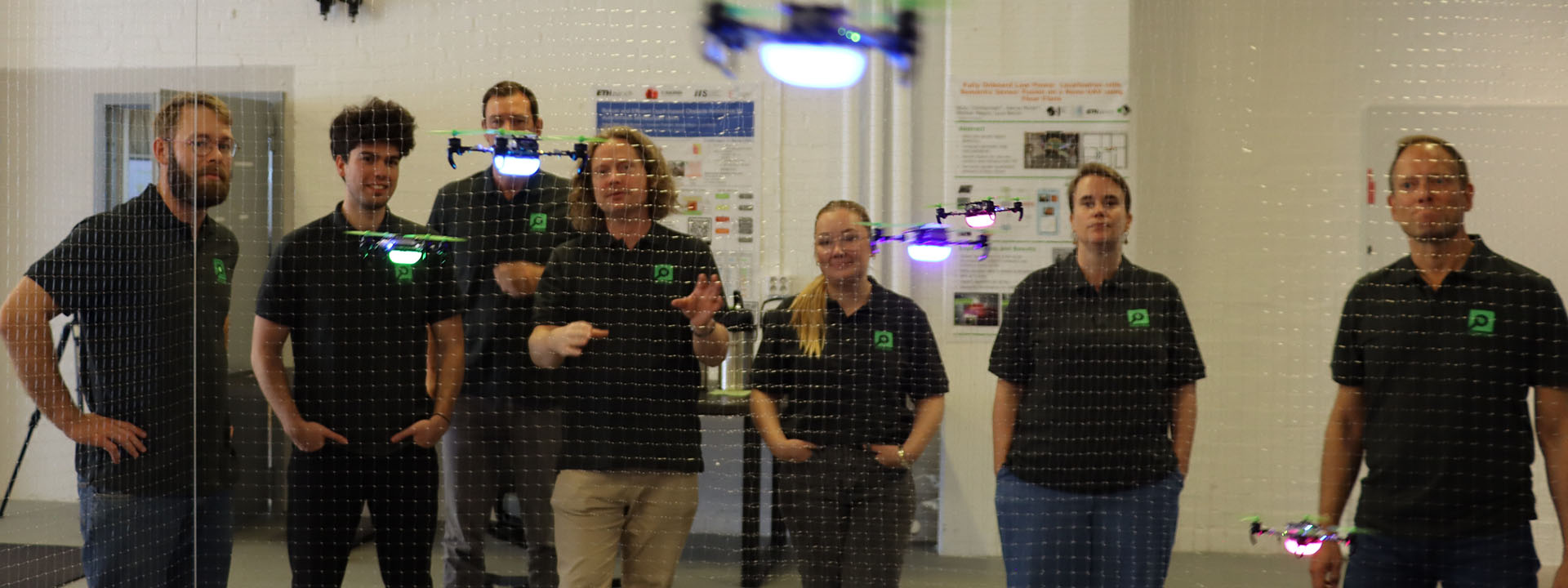
Three is a swarm.
Benefits of contributing – doing things together
Now why would you contribute? You have made an improvement, and maybe you think: Well, I have what I need, there is no direct value for me to make this change available to everyone. Or maybe you think it is an issue that only you have encountered, or that the change is not big enough to merge to the main repository. Or too much work to do it… Here is the good thing: as soon as you let us know what you are working on, we can help you understand the value and the effort of that change request – we know the community, what it is doing and what it needs. We also know how to take an idea and turn it into a product. Once you have said “I have an idea”, we will take the torch that you lit and push the idea forward. You will be accredited for the contribution (e.g. your name will show in our repository), but we will take the responsibility for it: We will test it, support it and maintain it, so that you don’t have to. We will make sure it follows the evolution of the software.
Another benefit of contributing is that when you contribute, another person somewhere else, working on similar things, is also contributing. We truly believe that the more our users contribute, the more our users contribute – the positive spiral mentioned earlier. There is a community out there, and it is filled with talented and knowledgeable people; it is welcoming and it is simply great to be a part of. This seems like a fitting place to say: Thank you for being awesome, community! We are so happy to have you.
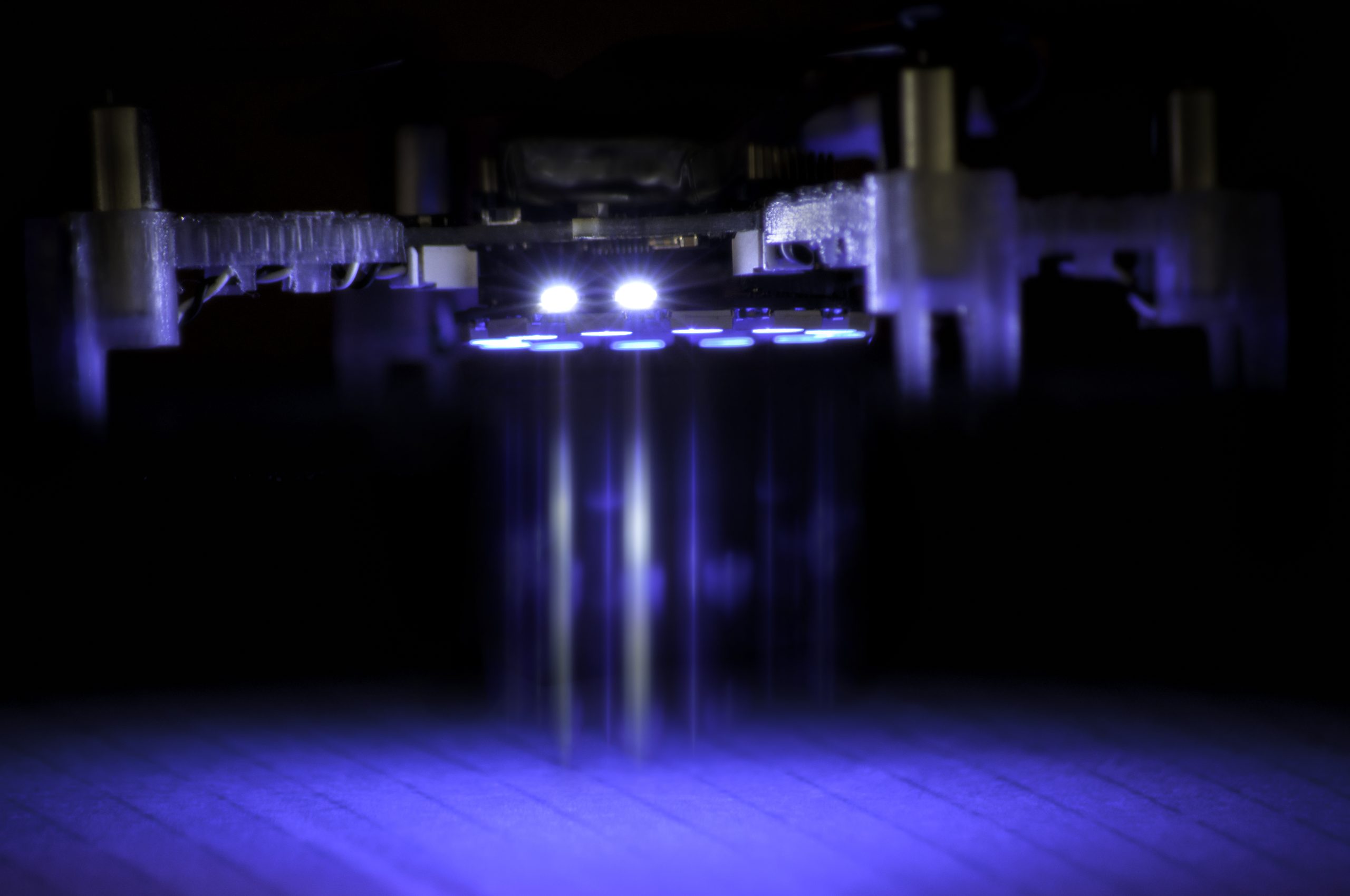
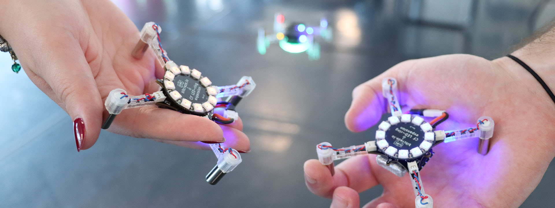
Lending each other a helping hand when needed.
Some recent examples
Over the years a number of external contributions have been made, all of which have been appreciated around the globe. Here are a few recent ones:
Solution of buffer overflow in syslink
A change doesn’t have to be big to be valuable. This is a great example of finding a bug, and fixing it. Deep in the firmware things become quite niche, and therefore difficult to understand if you don’t have that specific competence.
This was contributed by a user who found that there was a limitation to what angle could be commanded when flying the Crazyflie in manual mode using the Mellinger controller.
Thrust battery compensation is an external contribution to begin with. Here is a pull request to improve the documentation of it, in order to increase usability. Good for everyone!
We do our best to make all our software work on as many operating systems as possible. This can be difficult though, and yet very appreciated by a lot of people when it works. Here is an example of a change that makes it easier to build Out Of Tree controller on macOS.
The Flapper Nimble has completely different aerodynamic properties than a Crazyflie. This work adds the possibility to account for that in the Extended Kalman Filter (EKF) of the onboard firmware.
For software contributions, the current procedure is to fork the repository for which you want to do a change, and then create a pull request to the original repository from your fork. If you feel that you are not ready to do that, or have questions, then please reach out via email or Github discussions in the corresponding repository. We are happy to discuss ideas before turning them into pull requests. During the process of merging the change into the main branch, we might ask you to provide additional information. This is because we want to make sure we fully understand what problem you are trying to solve and how. Doing so, we can take over the responsibility, and you can let go of it (if you want to). Smaller changes usually means less effort, and vice versa. However, you can contribute with as much time and effort as you see fit.
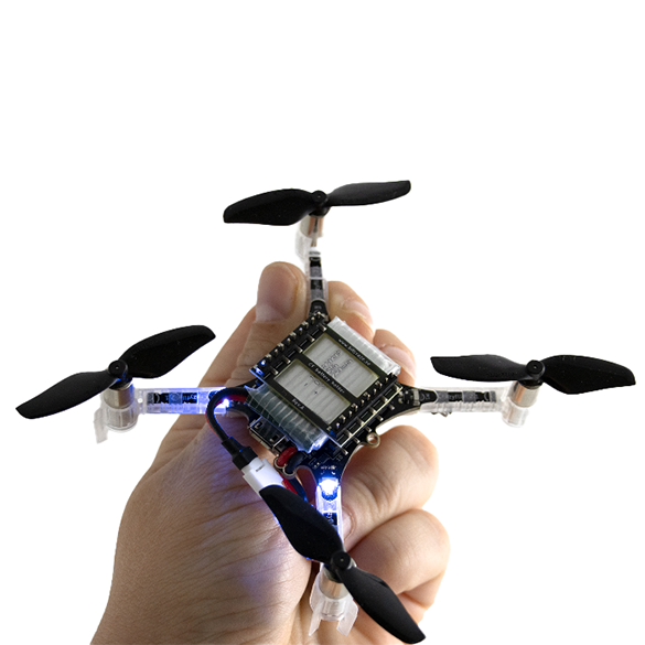
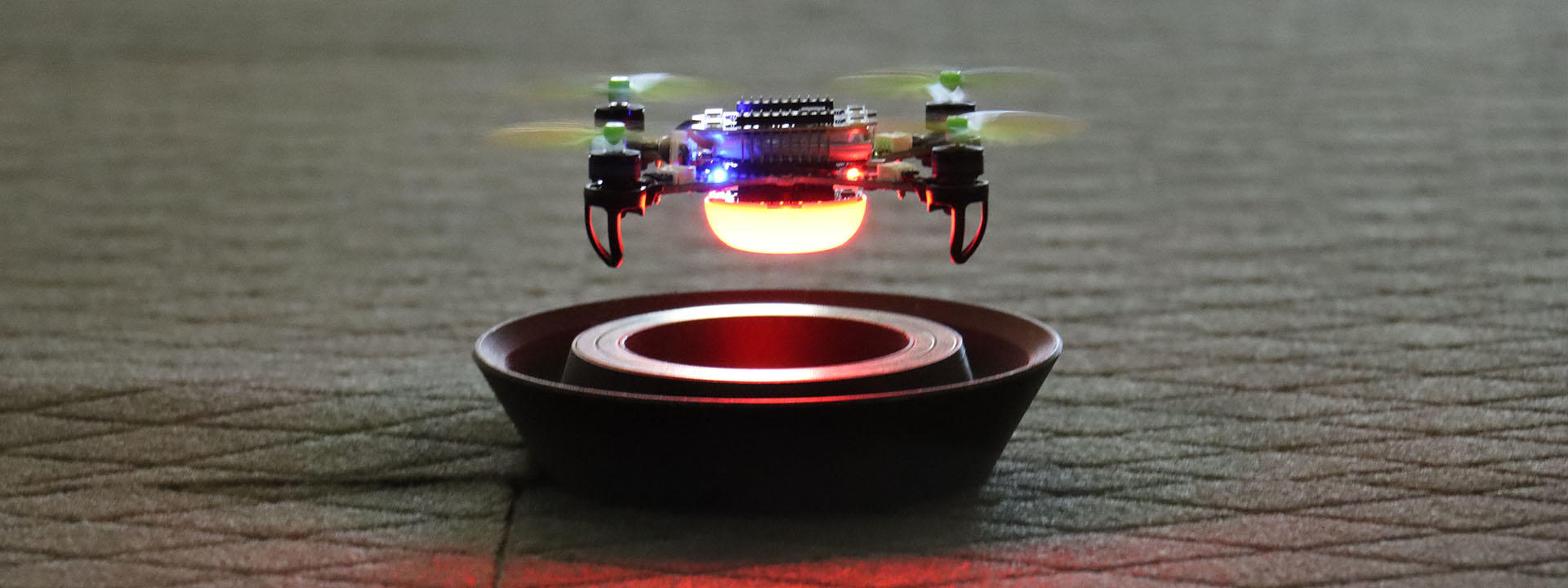
Ready for takeoff.
Worth noting also is that not all ideas or pull requests will end up in changes in the software. There could be a number of reasons for an idea being discarded, where effort compared to value is the main justification. Whatever happens we promise to have an open dialogue about your idea, and that we are transparent with the decisions that we make, so that future contributions will be even better! Just remember, no idea is too big or too small to pitch.
Pushing forward, together
Making it easier to do contributions, and increase the quality of the contributions, is something that we are dedicated to and prepared to make efforts for. So if you have any thoughts on how we can improve, or think about reasons that keep you from contributing that we can solve, we would very much like to hear it!
We are looking forward to collaborating on all amazing, crazy, improving and mind-blowing ideas out there!
We built a small drone for people who want to understand how things fly. The community took it considerably further than that. The citations keep arriving from directions we didn’t anticipate. Spacecraft dynamics. Tactile human-swarm interaction. Onboard deep learning. Mapping algorithms that fit inside a nano-drone’s compute budget. The platform’s combination of openness, known dynamics, repeatable behavior, and low replacement cost turns out to be useful for a wider set of problems than any single team could have imagined building for.
What follows is by no means a comprehensive survey, but rather a selection of research areas where the Crazyflie has found a home, each illustrated with recent work. We find it genuinely interesting that the same hardware can be useful across this range, and we hope it gives other researchers a sense of what is possible.
1. Decentralized Multi-Agent Coordination and Swarm Control
Multi-agent coordination is probably the research area most closely associated with the Crazyflie, and for good reason. The platform’s light weight, predictable dynamics, and relatively low cost per unit make it practical to run experiments with enough agents to observe emergent swarm behavior, rather than just simulating it. A lab can field a meaningful swarm without the capital outlay that larger platforms would require.
Recent work has pushed this in some interesting directions. Decentralized approaches, where each agent makes decisions based on local information rather than a central planner, are particularly well-served by a platform where individual failures don’t cascade into catastrophic system loss. Research on collision avoidance, formation control, and consensus algorithms benefits from hardware that can absorb the crashes that inevitably happen when you are testing novel coordination strategies.
The ROS 2 ecosystem around the Crazyflie has matured considerably, with frameworks like Crazyswarm2 enabling standardized multi-drone experiments that other labs can replicate. The reproducibility this enables is meaningful: a coordination result demonstrated on Crazyflies in one lab is demonstrable in another (see “CrazyChoir: Flying Swarms of Crazyflie Quadrotors in ROS 2” (arXiv)).
2. Onboard AI and Edge Inference at Nano Scale
What can you fit inside a couple of dozen grams grams and still have compute left over for intelligence? Quite a lot, it turns out, especially when researchers are motivated to find out. The AI Deck, which adds a GAP8 system-on-chip with a camera and Wi-Fi, opened a wave of work on fully onboard perception and inference pipelines on nano-UAVs.
More recently, work using custom expansion decks with the GAP9 processor has enabled onboard SLAM and scan-matching at take-off weights around 46 grams, showing that the platform’s expansion architecture makes it a meaningful target even as compute capabilities grow. See “Ultra-Lightweight Collaborative Mapping for Robot Swarms” (arXiv).
The Crazyflie’s transparent hardware design is important here: researchers can build custom decks, verify the power budget, and integrate new silicon without waiting for a vendor to offer an approved configuration.
3. Spacecraft and Orbital Dynamics Simulation
Researchers at the University of Houston, in collaboration with the US Air Force Research Laboratory, used Crazyflie drones to simulate the relative motion dynamics of spacecraft in formation, specifically the Clohessy-Wiltshire equations that describe how objects move relative to each other in near-circular orbit.
The reasoning is practical: testing spacecraft autonomy on-orbit is expensive and high-risk. Ground-based testbeds using air bearings exist, but are complex and space-intensive. A small fleet of Crazyflies, running scaled versions of orbital trajectories in an indoor lab, offers a much cheaper and more accessible way to validate formation-flying control laws and neural network guidance systems before committing to hardware that will be launched into space.
4. Reinforcement Learning: From Simulation to Real Hardware
Reinforcement learning (RL) for drone control has been a thriving research area for years, but the gap between simulation and physical hardware remains a hard problem to close. The Crazyflie’s well-documented dynamics, consistent manufacturing, and open firmware have made it a preferred target for sim-to-real transfer research, because the sim and the real thing can be brought into close agreement.
Work in this space spans a wide range of problem settings. Multi-agent RL for collision-free navigation, safe RL with control barrier functions, landing on moving targets, and agile trajectory following in cluttered environments have all been demonstrated on Crazyflie hardware. A common thread is that the platform’s low inertia and predictable response make it a fair test: there is nowhere to hide on a platform this light and responsive, and if the policy is sloppy, it falls (see “AttentionSwarm: Reinforcement Learning with Attention Control Barier Function for Crazyflie Drones in Dynamic Environments” (arXiv).
The “LEARN framework”, which claims to run a compact attention-based RL policy on six Crazyflies for multi-robot navigation through 0.2-meter gaps at 2 m/s, is a recent example of how far this line of work has come. The system runs fully onboard, using only time-of-flight sensors, and transfers directly from simulation to real hardware without fine-tuning. See “LEARN: Learning End-to-End Aerial Resource-Constrained Multi-Robot Navigation” (arXiv).
5. Human-Swarm Interaction and Expressive Robotics
An unexpected corner of the research community is the one that adopted the Crazyflie to the human-robot interaction field. It turns out that a swarm of small, quiet, slow-moving drones is a better vehicle for studying how humans interpret and respond to group robot behavior than many ground robot alternatives.
Work in this space ranges from the technical to the almost philosophical. Researchers have studied whether humans perceive swarm motion as intentional and communicative; whether vibrotactile feedback can give operators an intuitive sense of swarm state during physical interaction; how flight formation shapes emotional perception; and how to design impedance-controlled swarms that respond naturally to human touch (see “SwarmTouch: Tactile Interaction of Human with Impedance Controlled Swarm of Nano-Quadrotors” (arXiv).
The Crazyflie’s low injury risk in the event of a collision, its predictable behavior, and its ability to carry sensing and communication payloads make it well-suited to user studies where physical proximity and spontaneous human response are important variables. The fact that the platform is widely available also matters: HRI research benefits from results that can be reproduced in different lab environments with different participant populations.
Looking across these five areas, a pattern emerges. In each case, the research is not about the Crazyflie itself. The platform is a means, not an end.
What the Crazyflie provides is a credible physical substrate that researchers can trust to behave consistently, modify freely, and replace cheaply when something goes wrong. The open source firmware means the dynamics are fully inspectable. The transparent hardware means the platform can be extended with custom decks. The stable software ecosystem means results from one year’s experiments can be compared against another year’s, and against results from other labs using the same platform.
If your research uses the Crazyflie in a direction not represented here, we’d like to hear about it. The research portal at bitcraze.io/portals/research lists some of what we know about, but the community is larger and more inventive than any curated list can capture.
It’s that time of year again! ICRA 2026 (IEEE International Conference on Robotics & Automation) is just around the corner, and this year we’re heading to Vienna. We couldn’t be more excited about this one: Vienna is an incredible city, and we’ve been working on some things we can’t wait to share.
June 1–5, 2026. Come find us!
A reproducible testbed for aerial robotics research
We will be running a live autonomous flight system based on the Crazyflie platform.
The focus is not the flight itself, but what it enables. The system provides a controlled indoor environment where experiments can be repeated, variables isolated, and results compared over time.
This is aligned with how aerial robotics research is actually conducted: iteration speed, reproducibility, and observability matter more than scale in early and mid-stage research. Our platform is designed around those constraints.
Autonomous indoor flight for controlled experimentation
The setup demonstrates autonomous flight under conditions that remain stable across runs.
This allows researchers to evaluate control strategies, perception pipelines, and multi-robot coordination without environmental noise dominating results. It also reduces costs and operational overhead compared to larger platforms, which changes how frequently experiments can be run.
In practice, this makes it feasible to move from idea to validated result faster and with clearer insight into failure modes.
Used in swarm robotics, control, and physical AI research
The Crazyflie platform is used across domains such as swarm robotics, learning-based control, SLAM, and human–robot interaction.
It has been referenced in hundreds of peer-reviewed publications and is often used as a bridge between simulation and larger systems. The value is not in representing the final deployment environment, but in enabling rigorous, comparable experimentation at low cost and risk.
If you are working in these areas, we are interested in how your setup is structured and where constraints appear.
Share your work with us
If you are presenting work that involves the Crazyflie, we would like to see it.
Even better, if you do not need your poster after your session, bring it by the booth! We collect and display these as part of the broader body of work built on the platform. We will make sure it is appreciated properly.
Meet us at ICRA 2026
One of our favourite things about ICRA is getting to meet the community in person, hearing about your research, seeing what you’ve built with the Crazyflie, and exchanging ideas with people who are just as excited about small flying robots as we are. Whether you want to chat about your research, see the demo up close, or just catch up, our booth is the place to be. We love hearing about all the cool projects you’re working on with the Crazyflie, so don’t be shy!
If you are working with the Crazyflie, evaluating platforms, or exploring new research directions, stop by booth 91. You can also reach out at contact@bitcraze.io to schedule time.
We’re happy to announce that release 2026.04 is now available. This update introduces a dedicated CRTP port for the supervisor subsystem and a radio startup gate for more reliable early connections, along with a number of smaller bug fixes and quality-of-life improvements. Alongside the release, we’re launching a new crazyflie-demos repository with self-contained examples demonstrating real-world use cases. Thanks to our community contributors for their valuable additions to this release.
Major changes
Demos repository The new dedicated crazyflie-demos repository hosts more complex examples that combine features or subsystems to demonstrate best practices and real-world use cases. Every demo in the new repository is self-contained, with pinned software versions.
CRTP supervisor port A new dedicated CRTP port provides direct access to the supervisor subsystem, consolidating supervisor-related commands that had historically ended up on unrelated ports. Arming, crash recovery, and emergency stop commands now go through this port instead of being spread across the platform and localization ports. The old ports still accept these commands for backward compatibility. The new port also exposes supervisor state (armed, flying, tumbled, crashed, etc.) through a direct query, so clients no longer need to set up a log block just to check supervisor status.
Radio startup gate The STM32 now signals the nRF51 when it’s ready to receive radio packets. Previously, if a client connected during boot, packets could arrive before the firmware was ready to handle them, causing lockups.
Lighthouse calibration saving fix Fixed a bug that made saving lighthouse calibrations unreliable: a signature mismatch in a memory-read failure callback could leave the memory subsystem locked, blocking further reads until reconnect.
AI coding agents have become increasingly useful lately. The main reason, as far as I can understand, is that agents like Claude Code can close the loop: they can produce code, test it, and iterate. This is critical because models will make mistakes, and the feedback loop allows them to iteratively correct problems and usually converge on a working solution.
When trying to use coding agents with embedded systems, I quickly found myself becoming a manual tester, copy-pasting logs and describing behavior back to the agent. I was the one closing the loop, which is both inefficient and frustrating. So I started looking for ways to improve that.
Control by CLI
One of the great strengths of coding agents is that they can close the loop through the command line. They can invoke CLI tools, and by assembling them together they can achieve far more than any single tool would allow, this is essentially the Unix philosophy applied to AI-assisted development.
The most effective way to extend an agent’s capabilities that I’ve found so far is to build dedicated command line tools and let the agent use them. I ran a couple of experiments with dev boards where I had the agent create a small Python tool to control the board. The minimum useful functionality was: flash firmware, observe the console output, and reset the board. With just those three capabilities, the agent gains the ability to iterate almost entirely on its own.
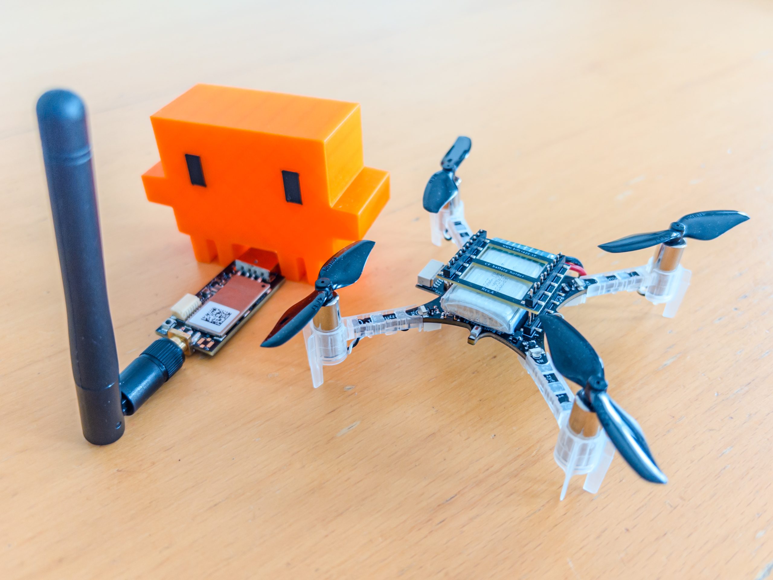
The crazyflie-agent-cli
This is where the idea came from for creating such a tool for the Crazyflie. I chose to write it in Rust, partly to exercise our newly developed Crazyflie Rust library.
The capabilities I gave it are:
Flash the Crazyflie using the bootloader
Reset the Crazyflie into bootloader or firmware mode
Console, stream the debug text output from the firmware
Parameters, read and write parameter values
Log variables, stream the value of log variables
This is roughly the minimum viable feature set for Crazyflie firmware development. Since AI coding agents already know how to write C code and compile projects, this is, in theory, enough to close the loop and let an agent implement new functionality, flash it, observe the behavior, find a bug, and iterate, just like in a normal development workflow.
Designing a CLI for agents, not humans
One design challenge worth mentioning: the Crazyflie communication model is inherently stateful. As a human, you would open an interactive client, connect to the drone, and then poke around, reading parameters, watching log variables, tweaking things live. That interactive, session-based workflow doesn’t translate well to agents, which can’t use interactive CLIs. Instead, the crazyflie-agent-cli uses a daemon/client architecture: the agent first launches a background daemon that establishes the radio connection, then uses separate one-shot commands to interact with the already-connected Crazyflie. It’s not the most ergonomic design for humans, you end up needing two terminals, but it turns out to work surprisingly well for an agent, which has no trouble managing background processes and firing off commands independently.
Putting it all together
The CLI gives the agent the capability to interact with the Crazyflie, but it also needs to know how to use it. We could tell the agent at the start of every session “here is a tool you can use,” and it would figure things out by calling --help. But a much more efficient approach is to use skills.
Alongside the CLI, I created a skill that teaches the agent how to use the tool for Crazyflie firmware development: what the workflow looks like, how to flash, how to debug. This is what truly closes the loop, once the skill is in place, the agent knows what a Crazyflie is, how to flash it, and how to debug it, without needing much guidance.
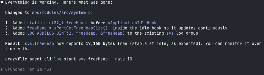
The end result: Claude Code can implement simple firmware functionality largely in one shot, and even when it doesn’t get it right the first time, it will iterate and generally get there.
Here is an example prompt that works end-to-end:
I have a Crazyflie on channel 80, 2M, default address. Add a log variable that exposes
the free heap size so I can monitor it over time. Build, flash, and verify the new
variable appears in the log list.Code language:PHP(php)
After a little while, the Crazyflie has been flashed, functionality has been verified and result looks something like:
Conclusion
This tool is not an official Bitcraze product, it’s a Fun Friday project. But we think it’s a nice demonstration of what is becoming possible with AI coding agents. By closing the loop, we can start to accelerate firmware development the same way AI has already accelerated other kinds of software development. That said, this is a force multiplier, not a replacement for engineering judgment. The human still needs to be in the loop.
For instance, I believe this CLI is already capable enough to let an agent bring up a new deck with a new sensor, exactly the kind of scoped, iterative task where the available functionality is sufficient. The tool could certainly be improved with more features, and we’ll see how much that happens. But we expect it will likely find its way into some of our day-to-day Crazyflie work at Bitcraze.
For the time being, treat it as an experiment and an example, not a finished product. The code is on GitHub at ataffanel/crazyflie-agent-cli if you want to try it out.
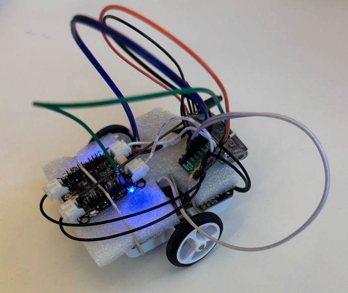
At Bitcraze, we spend a lot of time making things fly. Even though flying robots are, and will always be, fascinating to watch , every now and then it’s refreshing to try something different. Last Friday, I started exploring an idea that has been lying around for a while now: having a ground robot with the same Crazyflie infrastructure – the radio communication, the deck ecosystem and the cfclient connection. This robot is also known as the Crazyrat.
Fair warning: this is a first prototype, and it definitely looks like one. Jumper wires going in every direction, plastic foam and rubber bands to keep everything in place. But it drives, and it drives fast! That’s enough to call it a success and write about it.
Hardware
The entire vehicle was built around the Crazyflie Bolt 1.1, using its motor connectors, and specifically the S pins to drive a small H-bridge motor driver, enabling proper bidirectional DC motor control. To make it possible to drive the H-bridge, the motors must be configured as brushed.
For the motor driver, I used a Pololu DRV8833 Dual Motor Driver Carrier. I experimented with two different motor sets: one with a 75:1 gear ratio and one with 15:1. Even though the 75:1 motors offered better precision and were easier to drive, the 15:1 setup was the clear winner due to their speed.
The motors, the chassis and the power supply were taken from a Pololu 3pi+ robot.
Firmware
For the firmware, I used the Out-Of-Tree functionality of the crazyflie-firmware which makes it easy to integrate custom controllers. The controller itself is relatively simple. It maps pitch and yaw commands sent from the cfclient to throttle and steering respectively. Then, it sends the calculated values directly to the motors as PWM signals.
To test the prototype, I used a gamepad and drove it through the cfclient – no modifications are required. Here’s a video showing the capabilities of the Crazyrat using the 15:1 motor setup.
What’s Next
This project was a really fun learning experience on the potential and the limitations of the ground robots. These are some of the directions I plan to explore in the future:
Robust design – Design a proper chassis, clean up the wiring and make the whole vehicle smaller, to fit better in the Crazyflie ecosystem.
Deck integration – Use either the Lighthouse or the LPS deck for positioning and the Multi-Ranger deck for obstacle detection.
Experiment – Explore heterogeneous multi-agent swarming scenarios with the Crazyrat and the Crazyflie.
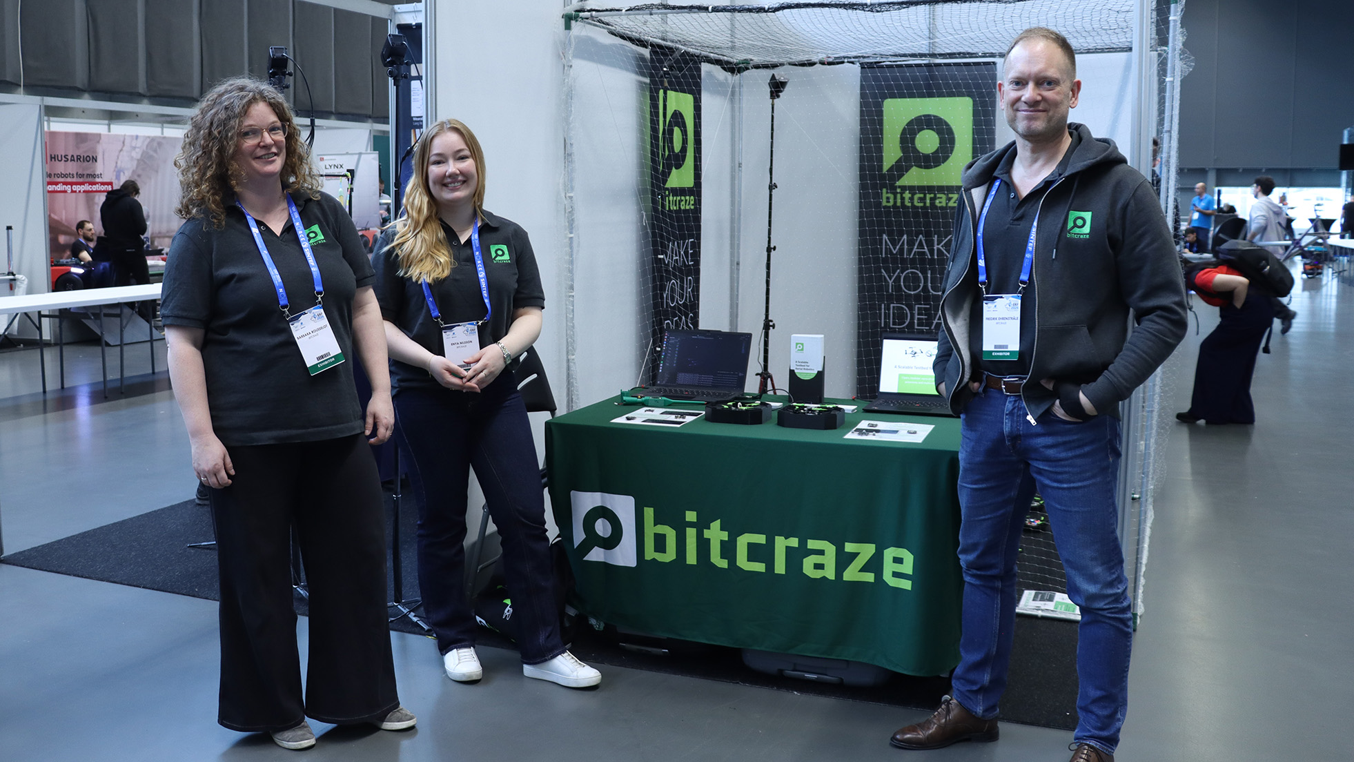
Booth #90 is running. Here’s what we’re showing and why we think it’s relevant to the conversations happening at the European Robotics Forum this week.
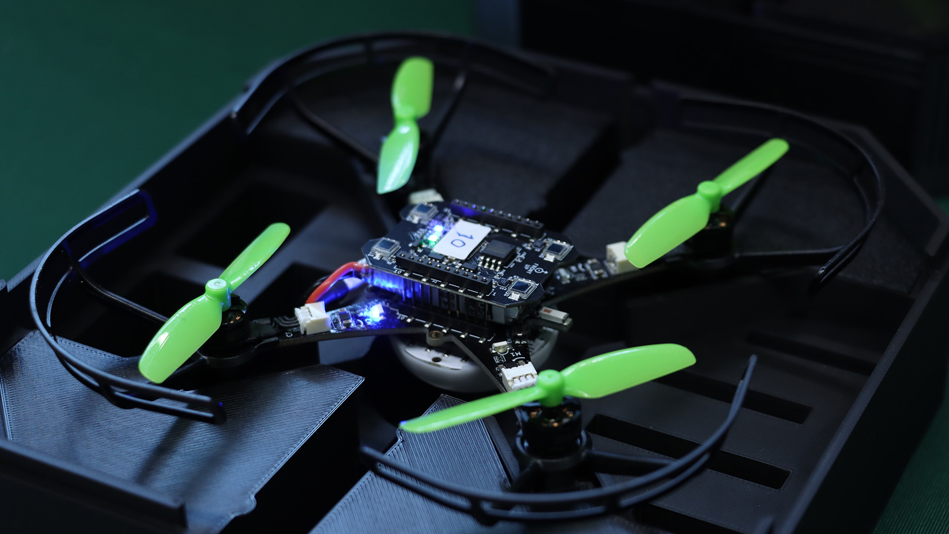
A Decentralized Brushless Swarm
The centerpiece is an evolution of the Decentralized Brushless Swarm demo we published last year. Multiple Crazyflie 2.1 Brushless drones share a volume with no central trajectory planner. Each agent handles its own state estimation, neighbor awareness, and collision avoidance independently. The swarm is fault-tolerant by design: individual failures don’t cascade.
What makes this relevant as a testbed is not the flight itself, but what it lets you study. Decentralized coordination, emergent behavior, and the gap between simulated and physical multi-agent dynamics are all things you can actually probe here, at a scale and cost that makes iteration realistic.
The Swarming Interface
We’re showing a new interface for the first time at ERF. It surfaces per-agent state in real time: position, velocity, battery, role, giving you visibility into what the swarm is doing and why, not just the flight envelope. We’ll write up the technical details separately, but if you want to see it running, the booth is the right place.
A Touch of Magic!
We have built a magic wand. It is a Lighthouse-based device that lets you grab a drone, or a group of them, and steer with your hand. It started as a side project and ended up being a surprisingly good way to demonstrate how the positioning system responds to real-time input. Worth a look if you’re nearby.
Come Find Us
We’re at booth #90 through Thursday March 27. The conversations we’re most interested in are about research infrastructure: how teams design testbeds, what the handoff from simulation to hardware looks like in practice, and where small-scale indoor platforms fit into larger development pipelines.