We’re happy to announce that release 2025.09 is now available. This update includes Python 3.13 support and improved battery voltage compensation, along with enhanced trajectory control capabilities. The release also features substantial stability and architectural work that lays the groundwork for upcoming features and products. Thanks to our community contributors for their valuable additions to this release.
Major changes
Python 3.13 support Added support for Python 3.13, with preparations already in place to ensure faster compatibility when Python 3.14 releases.
Improved battery voltage compensation Enhanced voltage compensation for Crazyflie 2.1, 2.1+, and 2.1 with thrust upgrade kit provides more consistent flight performance across battery discharge cycles. Crazyflie Brushless battery voltage compensation coming soon. Thanks to @Rather1337 for this contribution.
Manual flight setpoint packet New generic commander packet type for manual flight that allows dynamic switching between Angle and Rate modes for roll and pitch without re-flashing the firmware.
Fully relative trajectories Trajectories can now be initiated relative to the drone’s current yaw, not just position. This enables fully relative trajectory execution where subsequent trajectories maintain the drone’s current orientation. Thanks to @johnnwallace for this contribution.
Modular deck discovery architecture Replaced OneWire-only deck discovery with a modular backend system that supports multiple discovery protocols. This enables future deck communication methods while maintaining full backward compatibility with existing decks.
We are happy to announce the latest updates to the Crazyflie client and Python library. Major changes include improved persistent parameter management, enhanced plotting with new x-axis manipulation features, and new default logging configurations (for PID tuning). Minor updates include bug fixes and documentation improvements.
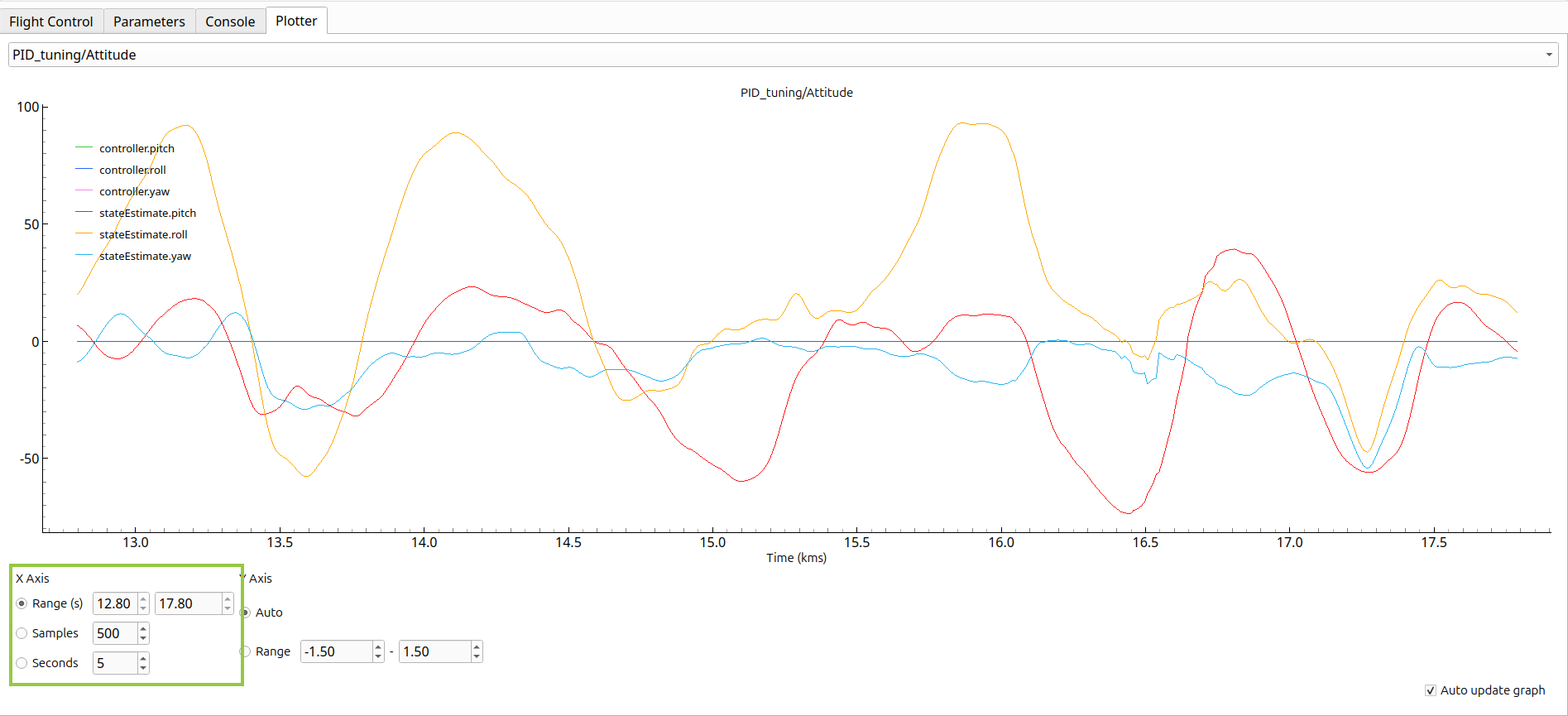
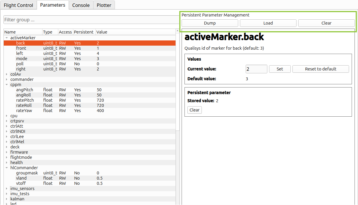
Updated plotter tab. Besides the existing option for a number of samples, users can now set x-axis limits to a number of seconds or a time range.Updated parameters tab. Users can now mass dump/load persistent parameters to/from a file, or clear all stored persistent parameters.
Before we start settling down and preparing for Christmas, it’s time for another release! The last one was before the summer in July, and we’ve had quite a few changes on the development master branch that we’d like to share. You can now download the latest Cfclient through pip and install the newest firmware on the Crazyflie to 2023.11 via the CFclient.
Latest changes in CFclient and Cflib
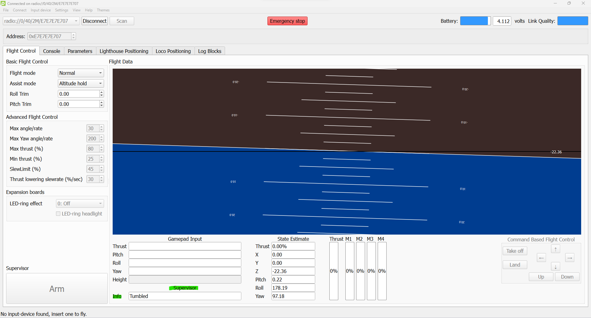
The most significant change in the CFclient is that we have finally transitioned from QT5 to QT6 for the GUI graphics. Additionally, we have addressed some issues with the toolboxes. Finally, we have added an information box to indicate the state of the supervisor, such as whether the Crazyflie is considered tumbled, flying, or if a restart is required because it is locked.
Cfclient when the crazyflie is tumbled with supervisor info
For the backend, namely the Crazyflie Python library, some important changes have been implemented. Along with fixes to the parameter and logging framework, full-state setpoints have been introduced. This feature has existed in firmware for a while due to the Crazyswarm1 project (now Crazyswarm2), but it wasn’t implemented in the cflib until now. Additionally, it’s now necessary to use `notify_setpoint_stop` in cases of switching between high-level setpoints and regular position setpoints. There is also a generic motion capture example now based on the libmotioncapture library.
Note that even though the CFclient has been converted to QT6, there are several examples in the Cflib folder that have not been updated yet. This will be fixed soon, and a ticket has been created for it. Additionally, in the Bitcraze-VM, there have been some reported issues with QT6 (see this ticket).
Latest changes in the firmware
The firmware has undergone some important changes too. On the STM side of things, the hybrid TDOA mode has been merged (check out this recent blog post). This feature is still considered experimental, so please refer to the documentation for the right settings. Additionally, support for the supervisor information box in the CFclient has been added. To utilize it, both the firmware and CFclient need to be updated. There is also a new example demonstrating communication between gap8 and cpx. Last but not least, it is now possible to create Python bindings for portions of the Kalman filter, mainly for the Loco positioning system. On the other hand, the NRF firmware has no added functionalities except for some build changes and fixes.
Crazyradio2 + LPS tools
We’ve also made some improvements in other firmware or tools. Starting with the Crazyradio2, which includes fixes for broadcasting (important for you Crazyswarm2 folks!). We also aimed to make a new release of LPS tools since we heard that people were experiencing issues with USB devices. Unfortunately, there are some problems with the GitHub release actions, so that will likely be delayed. For anyone facing USB issues, you can install the LPS tools from source with Python following the ReadMe’s instructions.
As we already announced last week in the Monday blog post, we will be having a developer meeting this Wednesday (6th Dec, 3 pm CET) regarding the Flow deck (refer to this discussion thread for joining information). Since we usually don’t fill up the entire hour, the last part of the developer meeting is available for some generic support questions face-to-face (online), including questions about the release!
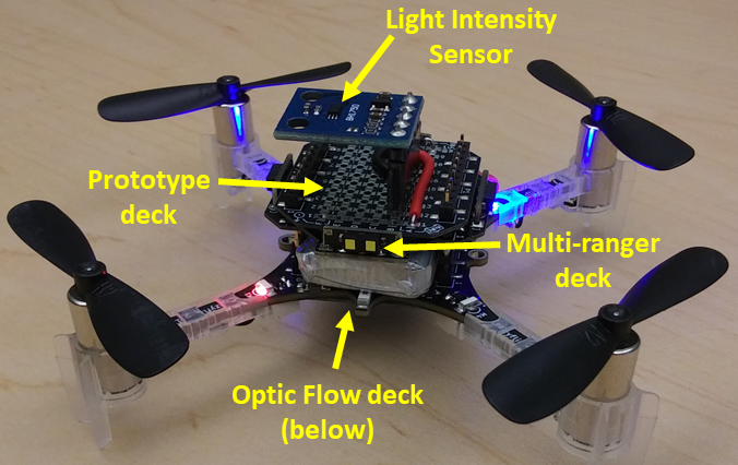
Our team’s Crazyflie quadcopter was equipped with Bitcraze’s Optic Flow deck and Multi-ranger deck. A BH-1750 light intensity sensor was soldered to a Bitcraze Prototype deck to complete our hardware.
The Crazyflie 2.1 was the perfect robotics platform for an introduction to autonomous robotics at the University of Washington winter quarter 2020. Our Bio-inspired Robotics graduate course completed a series of Crazyflie projects throughout the 10 weeks that built our skills in:
Python
Robot Operating System (ROS)
assembling custom sensors
writing new drivers
designing and testing control algorithms
trouble shooting and independent learning
The course was offered by UW Mechanical Engineering’s Autonomous Insect Robotics Laboratory, headed by Dr. Sawyer B. Fuller. The course was supported by PhD candidate Melanie Anderson, who has done fantastic research with her Crazyflie-based Smellicopter. The final project was an opportunity to turn a Crazyflie quadcopter into a bio-inspired autonomous robot. Our three person team of UW robotics grad students included Nishant Elkunchwar, Krishna Balasubramanian, and Jessica Noe.
Light Seeking Run-and-Tumble Algorithm Inspired by Bacterial Chemotaxis
The goal for our team’s Crazyflie was to seek and identify a light source. We chose a run-and-tumble algorithm inspired by bacterial chemotaxis. For a quick explanation of bacterial chemotaxis, please see Andrea Schmidt’s explanation of chemotaxis on Dr. Mehran Kardar’s MIT teaching page. She provides a helpful animation here.
In both bacterial chemotaxis and our run-and-tumble algorithm, there is a body (the bacteria or the robot) that can:
move under its own power.
detect the magnitude of something in the environment (e.g. chemical put off by a food source or light intensity).
determine whether the magnitude is greater or less than it was a short time before.
This method works best if the environment contains a strong gradient from low concentration to high concentration that the bacteria or robot can follow towards a high concentration source.
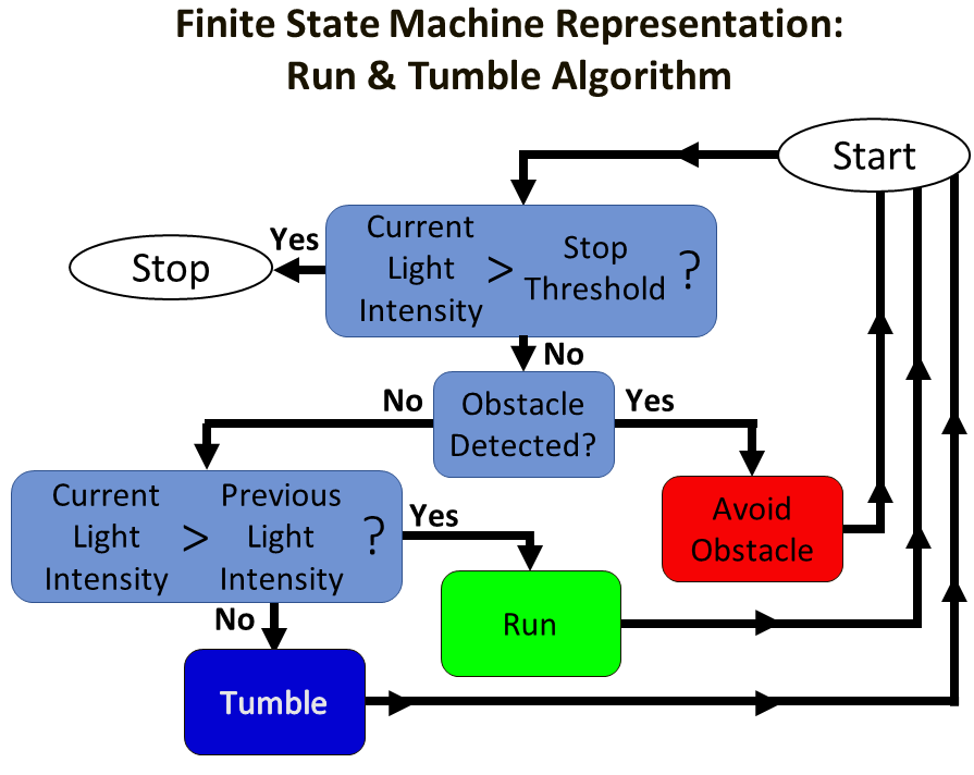
The details of the run-and-tumble algorithm are shown in a finite state machine diagram below. The simple summary is that the Crazyflie takes off, begins moving forward, and if the light intensity is getting larger it continues to “Run” in the same direction. If the light intensity is getting smaller, it will “Tumble” to a random direction. Additional layers of decision making are included to determine if the Crazyflie must “Avoid Obstacle”, or if the source has been reached and the Crazyflie quadcopter should “Stop”.
The run-and-tumble algorithm represented as a finite state machine.
Crazyflie Hardware
To implement the run-and-tumble algorithm autonomously on the Crazyflie, we needed a Crazyflie quadcopter and these additional sensors:
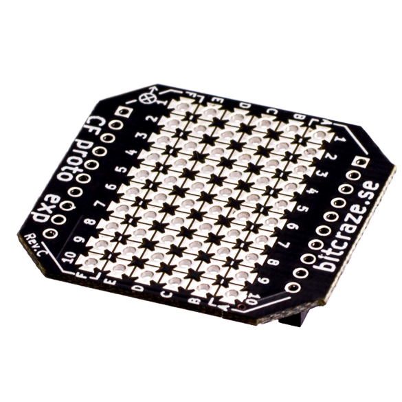
Bitcraze Prototype deck with BH-1750 light intensity sensor
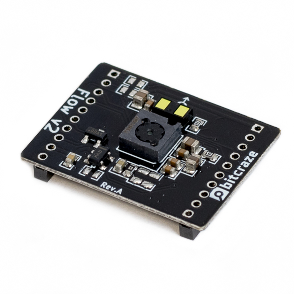
The Optic Flow deck was a key sensor in achieving autonomous flight. This sensor package determines the Crazyflie’s height above the surface and tracks its horizontal motion from the starting position along the x-direction and y-direction coordinates. With the Optic Flow installed, the Crazyflie is capable of autonomously maintaining a constant height above the surface. It can also move forward, back, left, and right a set distance or at a set speed. Several other pre-programmed movement behaviors can also be chosen. This Bitcraze blog post has more information on how the Flow deck works and this post by Chuan-en Lin on Nanonets.com provides more in-depth information if you would like to read more.
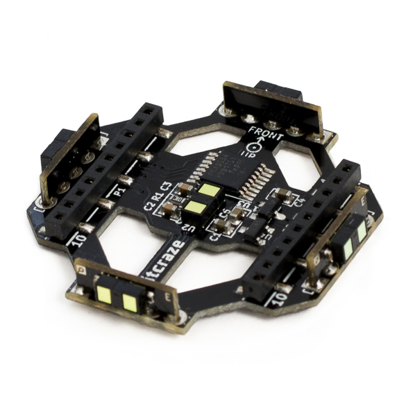
The Bitcraze Multi-ranger deck provided the sensor data for obstacle avoidance. The Multi-ranger detects the distance from the Crazyflie to the nearest object in five directions: forward, backward, right, left, and above. Our threshold to trigger the “Avoid Obstacle” behavior is detecting an obstacle within 0.5 meters of the Crazyflie quadcopter.
The Prototype deck was a quick, simple way to connect the BH-1750 light intensity sensor to the pins of the Crazyflie to physically integrate the sensor with the quadcopter hardware. This diagram shows how the header positions connect to the rows of pads in the center of the deck. We soldered a header into the center of the deck, then soldered connections between the pads to form continuous connections from our header pin to the correct Crazyflie header pin on the left or right edges of the Prototype deck. The Bitcraze Wiki provides a pin map for the Crazyflie quadcopter and information about the power supply pins. A nice overview of the BH-1750 sensor is found on Components101.com, this shows the pin map and the 4.7 kOhm pull-up resistor that needs to be placed on the I2C line.
It was easy to connect the decks to the Crazyflie because Bitcraze clearly marks “Front”, “Up” and “Down” to help you orient each deck relative to the Crazyflie. See the Bitcraze documentation on expansion decks for more details. Once the decks are properly attached, the Crazyflie can automatically detect that the Flow and Multi-Ranger decks are installed, and all of the built-in functions related to these decks are immediately available for use without reflashing the Crazyflie with updated firmware. (We appreciated this awesome feature!)
Crazyflie Firmware and ROS Control Software
Bitcraze provides a downloadable virtual machine (VM) to help users quickly start developing their own code for the Crazyflie. Our team used a VM that was modified by UW graduate students Melanie Anderson and Joseph Sullivan to make it easier to write ROS control code in the Python coding language to control one or more Crazyflie quadcopters. This was helpful to our team because we were all familiar with Python from previous work. The standard Bitcraze VM is available on Bitcraze’s Github page. The Modified VM constructed by Joseph and Melanie is available through Melanie’s Github page. Available on Joseph’s Github page is the “rospy_crazyflie” code that can be combined with existing installs of ROS and Bitcraze’s Python API if users do not want to use the VM options.
“crazyflie-firmware” – a set of files written in C that can be uploaded to the Crazyflie quadcopter to overwrite the default firmware
In the Bitcraze VM, this folder is located at “/home/bitcraze/projects/crazyflie-firmware”
In the Modified VM, this folder is located at “Home/crazyflie-firmware”
“crazyflie-lib-python” (in the Bitcraze VM) or “rospy_crazyflie” (in the Modified VM) – a set of ROS files that allows high-level control of the quadcopter’s actions
In the Bitcraze VM, “crazyflie-lib-python” is located at “/home/bitcraze/projects/crazyflie-lib-python”
In the Modified VM, navigate to “Home/catkin_ws/src” which contains two main sets of files:
“Home/catkin_ws/src/crazyflie-lib-python” – a copy of the Bitcraze “crazyflie-lib-python”
“Home/catkin_ws/src/rospy_crazyflie” – the modified version of “crazyflie-lib-python” that includes additional ROS and Python functionality, and example scripts created by Joseph and Melanie
In the Modified VM, we edited the “crazyflie-firmware” files to include code for our light intensity sensor, and we edited “rospy-crazyflie” to add functions to the ROS software that runs on the Crazyflie. Having the VM environment saved our team a huge amount of time and frustration – we did not have to download a basic virtual machine, then update software versions, find libraries, and track down fixes for incompatible software. We could just start writing new code for the Crazyflie.
The Modified VM for the Crazyflie takes advantage of the Robot Operating System (ROS) architecture. The example script provided within the Modified VM helped us quickly become familiar with basic ROS concepts like nodes, topics, message types, publishing, and subscribing. We were able to understand and write our own nodes that published information to different topics and write nodes that subscribed to the topics to receive and use the information to control the Crazyflie.
A major challenge of our project was writing a new driver that could be added to the Crazyflie firmware to tell the Crazyflie system that we had connected an additional sensor to the Crazyflie’s I2C bus. Our team referenced open-source Arduino drivers to understand how the BH-1750 connects to an Arduino I2C bus. We also looked at the open-source drivers written by Bitcraze for the Multi-ranger deck to see how it connects to the Crazyflie I2C bus. By looking at all of these open-source examples and studying how to use I2C communication protocols, our team member Nishant Elkunchwar was able to write a driver that allowed the Crazyflie to recognize the BH-1750 signal and convert it to a sensor value to be used within the Crazyflie’s ROS-based operating system. That driver is available on Nishant’s Github. The driver needed to be placed into the appropriate folder: “…\crazyflie-firmware\src\deck\drivers\src”.
The second change to the crazyflie-firmware is to add a “config.mk” file in the folder “…\crazyflie-firmware\tools\make”. Information about the “config.mk” file is available in the Bitcraze documentation on configuring the build.
The final change to the crazyflie-firmware is to update the make file “MakeFile” in the location “…\crazyflie-firmware”. The “MakeFile” changes include adding one line to the section “# Deck API” and two lines to the section “# Decks”. Information about compiling the MakeFile is available in the Bitcraze documentation about flashing the quadcopter.
Making additions to the ROS control architecture
The ROS control architecture includes messages. We needed to define 3 new types of messages for our new ROS control files. In the folder “…\catkin_ws\src\rospy_crazyflie\msg\msg” we added one file for each new message type. We also updated “CMakeLists.txt” to add the name of our message files in the section “add_message_files( )”.
The second part of our ROS control was a set of scripts written in Python. These included our run-and-tumble algorithm control code, publisher scripts, and a plotter script. These are all available in the project’s Github.
Characterizing the Light Sensor
At this point, the light intensity sensor was successfully integrated into the Crazyflie quadcopter. The new code was written and the Crazyflie quadcopter was reflashed with new firmware. We had completed our initial trouble shooting and the next step was to characterize the light intensity in our experimental setup.
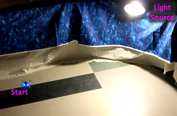
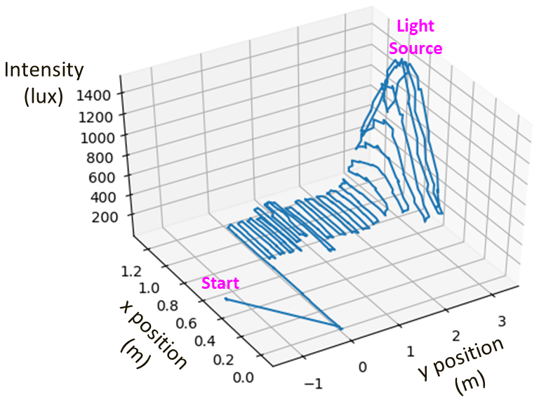
Experimental setup for light intensity characterization.
This characterization was done by flying the Crazyflie at a fixed distance above the floor in tightly spaced rows along the x and y horizontal directions. The resulting plot (below) shows that the light intensity increases exponentially as the Crazyflie moves towards the light source.
The light characterization allowed us to determine an intensity threshold that will only happen near the light source. If this threshold is met, the algorithm’s “Stop” action is triggered, and the Crazyflie lands.
Light intensity (units of lux) was experimentally characterized by piloting the Crazyflie in a linear pattern at a constant height above the ground. The resulting plot shows that light intensity is characterized by an exponential roll off in both the x and y directions.
Testing the Run-and-Tumble Algorithm
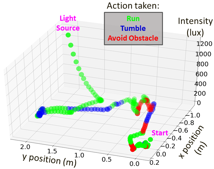
With the light intensity characterization complete, we were able to test and revise our run-and-tumble algorithm. At each loop of the algorithm, one of the four actions is chosen: “Run”, “Tumble”, “Avoid Obstacle”, or “Stop”. The plot below shows a typical path with the action that was taken at each loop iteration.
Flight Tests of the Run-and-Tumble Algorithm
In final testing, we performed 4 trial runs with 100% success locating the light source. Our test area was approximately 100 square feet, included 1 light source, and 2 obstacles. The average search time was 1:41 seconds.
The “Avoid Obstacle” and “Run” behavior are demonstrated in the above video clip (1.5x actual speed).
The “Run” and “Tumble” actions are demonstrated in the above video clip (2x actual speed). At the end, the “Stop” action is demonstrated when the light intensity reaches the threshold value of 800 lux, indicating that the Crazyflie has found the light source and should land.
Lessons Learned
This was one of the best courses I’ve taken at the University of Washington. It was one of the first classes where a robot could be incorporated, and playing with the Crazyflie was pure fun. Another positive aspect was that the course had the feel of a boot camp for learning how to build, control, test, and improve autonomous robots. This was only possible because Bitcraze’s small, indoor quadcopter with optic flow capability made it possible to safely operate several quadcopters simultaneously in our small classroom as we learned.
This development project was really interesting (aka difficult…) and we went down a few rabbit holes as we tried to level up our knowledge and skills. Our prior experience with Python helped us read the custom example scripts provided in our course for the ROS control program, but we had quite a bit to learn about the ROS architecture before we could write our own control scripts.
Nishant made an extensive study of I2C protocols as he wrote the new driver for the BH-1750 sensor. One of the biggest lessons I learned in this project was that writing drivers to integrate a sensor to a microcontroller is hard. By contrast, using the Bitcraze decks was so easy it almost felt like cheating. (In the nicest way!)
On the hardware side, the one big problem we encountered during development was accidentally breaking the 0.5 mm headers on the Crazyflie quadcopter and the decks. The male headers were not long enough to extend from the Flow deck all the way up through the Prototype deck at the top, so we tried to solder extensions onto the pins. Unfortunately, I did not check the Bitcraze pin width and I just soldered on the pins we all had in our tool kits: the 0.1 inch (2.54 mm) wide pins that we use with our Arduinos and BeagleBones. These too-large-pins damaged the female headers on the decks, and we lost connectivity on those pins. Fortunately, we were able to repair our decks by soldering on replacement female headers from the Bitcraze store. I wish now that the long pin headers were available back then.
In summary, this course was an inspiring experience and helped our team learn a lot in a very short time. After ten weeks working with the Crazyflie, I can strongly recommend the Crazyflie for robotics classes and boot camps.