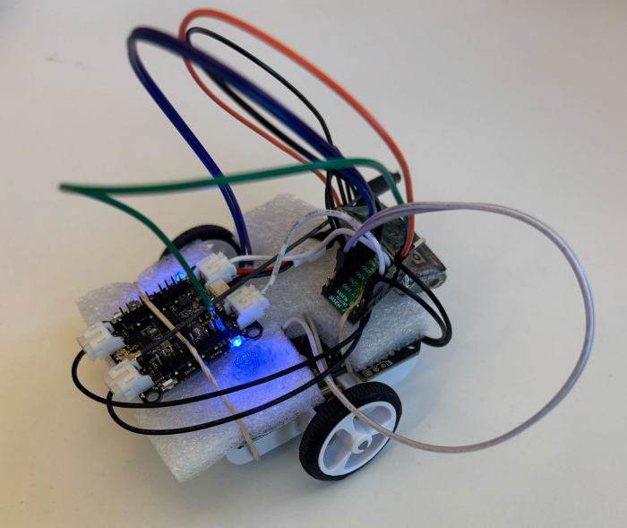
At Bitcraze, we spend a lot of time making things fly. Even though flying robots are, and will always be, fascinating to watch , every now and then it’s refreshing to try something different. Last Friday, I started exploring an idea that has been lying around for a while now: having a ground robot with the same Crazyflie infrastructure – the radio communication, the deck ecosystem and the cfclient connection. This robot is also known as the Crazyrat.
Fair warning: this is a first prototype, and it definitely looks like one. Jumper wires going in every direction, plastic foam and rubber bands to keep everything in place. But it drives, and it drives fast! That’s enough to call it a success and write about it.
Hardware
The entire vehicle was built around the Crazyflie Bolt 1.1, using its motor connectors, and specifically the S pins to drive a small H-bridge motor driver, enabling proper bidirectional DC motor control. To make it possible to drive the H-bridge, the motors must be configured as brushed.
For the motor driver, I used a Pololu DRV8833 Dual Motor Driver Carrier. I experimented with two different motor sets: one with a 75:1 gear ratio and one with 15:1. Even though the 75:1 motors offered better precision and were easier to drive, the 15:1 setup was the clear winner due to their speed.
The motors, the chassis and the power supply were taken from a Pololu 3pi+ robot.
Firmware
For the firmware, I used the Out-Of-Tree functionality of the crazyflie-firmware which makes it easy to integrate custom controllers. The controller itself is relatively simple. It maps pitch and yaw commands sent from the cfclient to throttle and steering respectively. Then, it sends the calculated values directly to the motors as PWM signals.
To test the prototype, I used a gamepad and drove it through the cfclient – no modifications are required. Here’s a video showing the capabilities of the Crazyrat using the 15:1 motor setup.
What’s Next
This project was a really fun learning experience on the potential and the limitations of the ground robots. These are some of the directions I plan to explore in the future:
Robust design – Design a proper chassis, clean up the wiring and make the whole vehicle smaller, to fit better in the Crazyflie ecosystem.
Deck integration – Use either the Lighthouse or the LPS deck for positioning and the Multi-Ranger deck for obstacle detection.
Experiment – Explore heterogeneous multi-agent swarming scenarios with the Crazyrat and the Crazyflie.
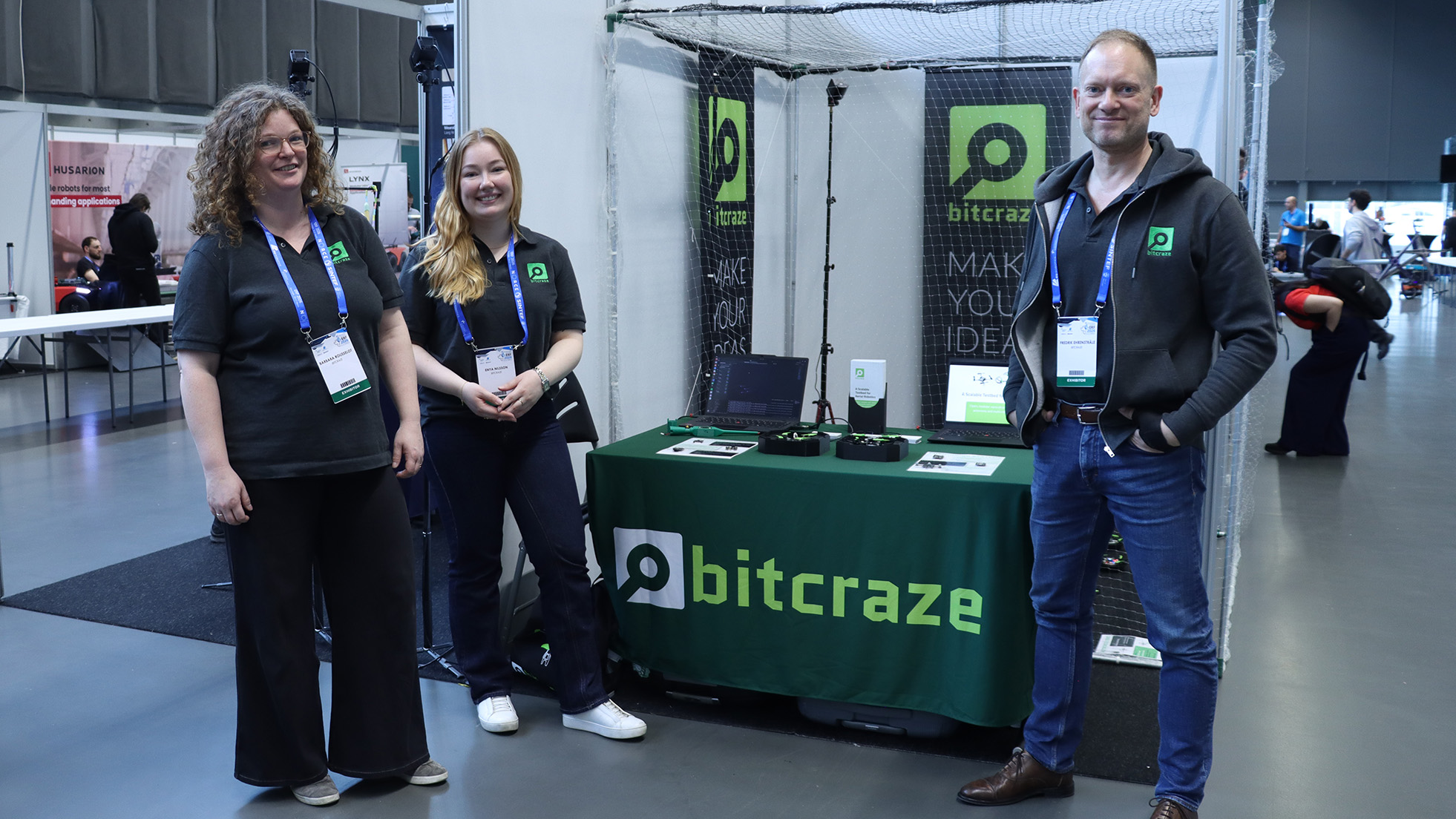
Booth #90 is running. Here’s what we’re showing and why we think it’s relevant to the conversations happening at the European Robotics Forum this week.
A Decentralized Brushless Swarm
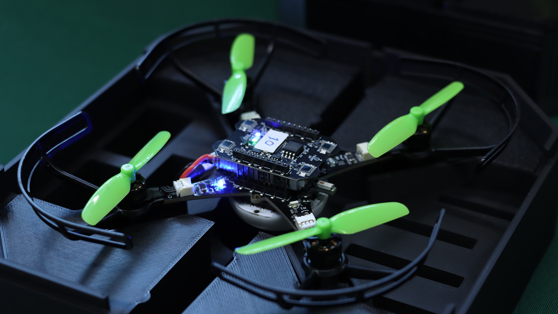
The centerpiece is an evolution of the Decentralized Brushless Swarm demo we published last year. Multiple Crazyflie 2.1 Brushless drones share a volume with no central trajectory planner. Each agent handles its own state estimation, neighbor awareness, and collision avoidance independently. The swarm is fault-tolerant by design: individual failures don’t cascade.
What makes this relevant as a testbed is not the flight itself, but what it lets you study. Decentralized coordination, emergent behavior, and the gap between simulated and physical multi-agent dynamics are all things you can actually probe here, at a scale and cost that makes iteration realistic.
The Swarming Interface
We’re showing a new interface for the first time at ERF. It surfaces per-agent state in real time: position, velocity, battery, role, giving you visibility into what the swarm is doing and why, not just the flight envelope. We’ll write up the technical details separately, but if you want to see it running, the booth is the right place.
A Touch of Magic!
We have built a magic wand. It is a Lighthouse-based device that lets you grab a drone, or a group of them, and steer with your hand. It started as a side project and ended up being a surprisingly good way to demonstrate how the positioning system responds to real-time input. Worth a look if you’re nearby.
Come Find Us
We’re at booth #90 through Thursday March 27. The conversations we’re most interested in are about research infrastructure: how teams design testbeds, what the handoff from simulation to hardware looks like in practice, and where small-scale indoor platforms fit into larger development pipelines.
During my first Fun Friday as a Bitcraze intern in 2021, I discovered the musical note definitions in the Crazyflie firmware and thought about creating a musical performance using the Crazyflie’s motors, but never followed through.
A few weeks ago I decided to finally take it on as a Fun Friday Project with the slightly more ambitious goal of playing music across several Crazyflies at once.
crazyflie-jukebox takes a MIDI file, preprocesses it into motor frequency events, then uploads and plays the song by spinning the motors accordingly. Each Crazyflie contributes 4 voices (one per motor), so polyphony scales directly with your drone count.
I implemented this as a firmware app and a Python script using the work-in-progress cflib2 (running on Rust lib back-end). You can find the repository here, try it for yourself! Be aware that certain note combinations can cause the Crazyflie to move, flip, or take off unexpectedly.
Fitting music into 4 motors
The pipeline starts by parsing the MIDI file with mido. From there, an interactive track selection step shows you the instrument names, note counts, and ranges for each track so you can pick exactly which ones to include. The selected notes are then converted from MIDI note numbers into Hz frequencies that the motors can work with.
Each Crazyflie can only play 4 simultaneous voices (one per motor) so there’s some work involved in squeezing music into that constraint. I implemented a couple different voice allocation strategies: melodic priority, which keeps the bass and melody prioritized; voice stealing, which works like a LRU synth; and a simple round robin, which just assigns each new note to the next motor in turn, cutting off whatever was playing there. There’s also a frequency range problem to deal with: motors only reliably produce pitches in roughly the C4–B7 range, so notes outside that window get octave-shifted to fit.
Upload protocol
Events are packed into compact 6-byte structs containing a delta timestamp, motor index, an on/off flag, and the target frequency. These get streamed to the firmware app using the app channel in a simple START; events; END sequence. The Crazyflie app has a buffer limit of 5000 events, which effectively caps the length and complexity of what you can play. The 5000-event buffer was an arbitrary choice and you could probably get away with more, but it was enough for most songs I threw at it.
Synchronization
One of the trickier elements of this project was keeping Crazyflies synchronized. For starting in sync, I didn’t do anything special: no broadcast, no t-minus countdown, just sending start commands to each drone in sequence and relying on cflib2 to do it fast enough that the delay is negligible. That said, I’ve only tested with a small number of Crazyflies. With a larger fleet you’d probably need to implement something for the initial sync.
The real challenge is drift over time. The STM32’s crystal is rated at around 0.1% tolerance. This sounds tiny, but in the worst case, over a 1-minute song that’s already ~120 ms of drift between two drones. In a musical context, humans start noticing timing offsets around 20-30 ms; less for percussive sounds, and less for trained musicians. So left uncorrected, drift would become very audible well before the song ends.
To fix this, all clocks are reset to zero at song start. The host then periodically sends resync packets containing its own timestamp in microseconds, and each Crazyflie applies an offset correction to stay aligned, which as a bonus also irons out any initial start latency.
Rough edges
The biggest design constraint is that a single track can’t be split across Crazyflies, so if a track has more than 4 simultaneous voices, some get dropped. I thought of each Crazyflie as its own instrument, which made sense at the time, but it does mean a dense MIDI tracks can’t be split across multiple drones, which feels limiting in hindsight.
The usable pitch range is about 4 octaves (C4–B7), and propellers need to be attached for accurate pitch since the motors need load to produce the right frequencies, which makes the whole thing a bit unsafe. Certain note combinations can cause a drone to move, flip, or behave unpredictably. Only brushed motors are supported, and there’s a hard 71-minute per-song limit on clock sync. But honestly, if you’re sitting there listening to a 71-minute song on your Crazyflie, the clock drift is the least of your problems.
This week we wanted to reflect on the progress that has been made lately in the Crazyflie ecosystem which will lead to bigger and better Crazyflie Swarms.
Radio communication
Like pointed out in the last blog post about Building a Crazyflie Flower Swarm with Rust, the new Rust Crazyflie library together with the new Crazyradio 2.0 has improved connection time and link efficiency by quite a bit.
It is now possible to connect swarms of multiple dozens of Crazyflies in seconds using a single radio and then make them fly while still getting position telemetry. So many Crazyflie on one radio does limit the maximum bandwidth per Crazyflie, but it does now work in a stable way!
Color LED deck
The recently released Color LED deck is a great addition to the ecosystem towards swarm. Its predecessor, the Led-ring Deck, has been used a lot by researchers to indicate state of individual Crazyflies in a Swarm. The Color LED Deck improves on that by providing a diffuser that allows to see the color from the side. This allows to mark states of big groups of Crazyflie much more clearly.
As a bonus, the Color LED Deck is very usable in other field like art and shows since it is much more visible and can be used to fly Crazyflies as “Flying Pixels”.
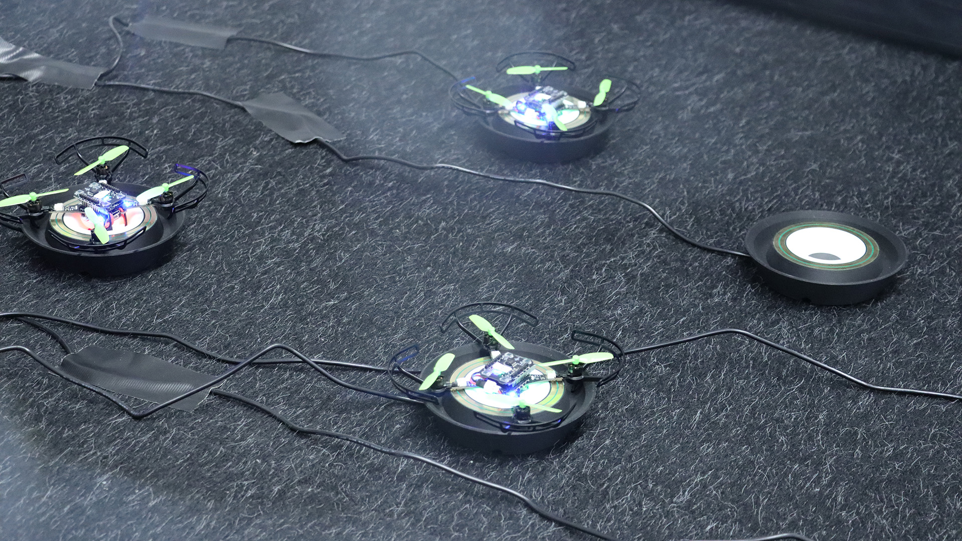
Autonomous landing and charging
Last year, we have released a Crazyflie 2.1 Brushless charging dock. This is a produced version of an idea we have been using with Crazyflie 2.1 and the Qi deck for years at fairs and conferences. It allows Crazyflies to autonomously land and charge. It is not only great for autonomous drone demos and shows but it also is a great waiting spots for swarms when doing research: the charging dock keeps the swarm charged so that when it is time to take off all the individuals starts with the same battery level.
Future endeavors
On the radio side there are still areas that would bring great improvement on communication stability. We are for example working on a channel-hopping communication protocol that should make the connection mostly immune to regular interference on 2.4GHz.
We are also working at improving other parts of swarm management, this includes for example solving the problem of flashing a full swarm of Crazyflie with the same firmware: we may be able to use broadcast messages more in order to drastically speed up the process instead of flashing the Crazyflie one per one.
Overall, working on bigger swarms allows us to work on the full stack and to make the Crazyflie a better drone for everybody.
Bitcraze will exhibit at the European Robotics Forum 2026 March 23-27 in booth #90, where we will demonstrate a live, autonomous indoor flight setup based on the CrazyflieTM platform. The demonstration features multiple nano-drones flying autonomously in a controlled environment and reflects how the platform is used in research and applied robotics development.
Why Indoor Aaerial Testbeds Matter
The purpose of the demonstration is not the flight itself, but the role such setups play in validating aerial robotics concepts. Indoor, small-scale aerial systems allow researchers and R&D teams to study autonomy, perception, control, and multi-robot coordination under safe and repeatable conditions. This makes it possible to explore system behavior, test assumptions, and iterate rapidly before moving to larger platforms or less controlled environments.
Applicable in Both Academia and Industrial R&D
Bitcraze is used both in academic research and in industrial R&D contexts. In academia, the platform supports experimental work in areas such as swarm robotics, learning-based control, and human–robot interaction, and has been referenced in hundreds of peer-reviewed research papers worldwide. In industry, similar setups are increasingly used as testbeds to de-risk development by validating ideas indoors before scaling to outdoor testing, larger drones, or other robotic systems that require higher investment and operational complexity.
Hands-on Discussions at the Booth
At the booth, the live flight cage will be complemented by hands-on access to additional drones, expansion decks, and software tools. This allows for technical discussions around hardware architecture, sensing and positioning options, software stacks, and how different configurations support different research or development goals.
The Conversations We Are at ERF to Have
At ERF, Bitcraze is there to engage in conversations about platforms, testbeds, and how ambitious aerial robotics ideas can be validated in a financially responsible, safe, and controlled manner. This includes discussions with academic groups, industrial R&D teams, and project partners working across the research-to-application spectrum.
Looking forward to the discussions in Stavanger in booth #90!
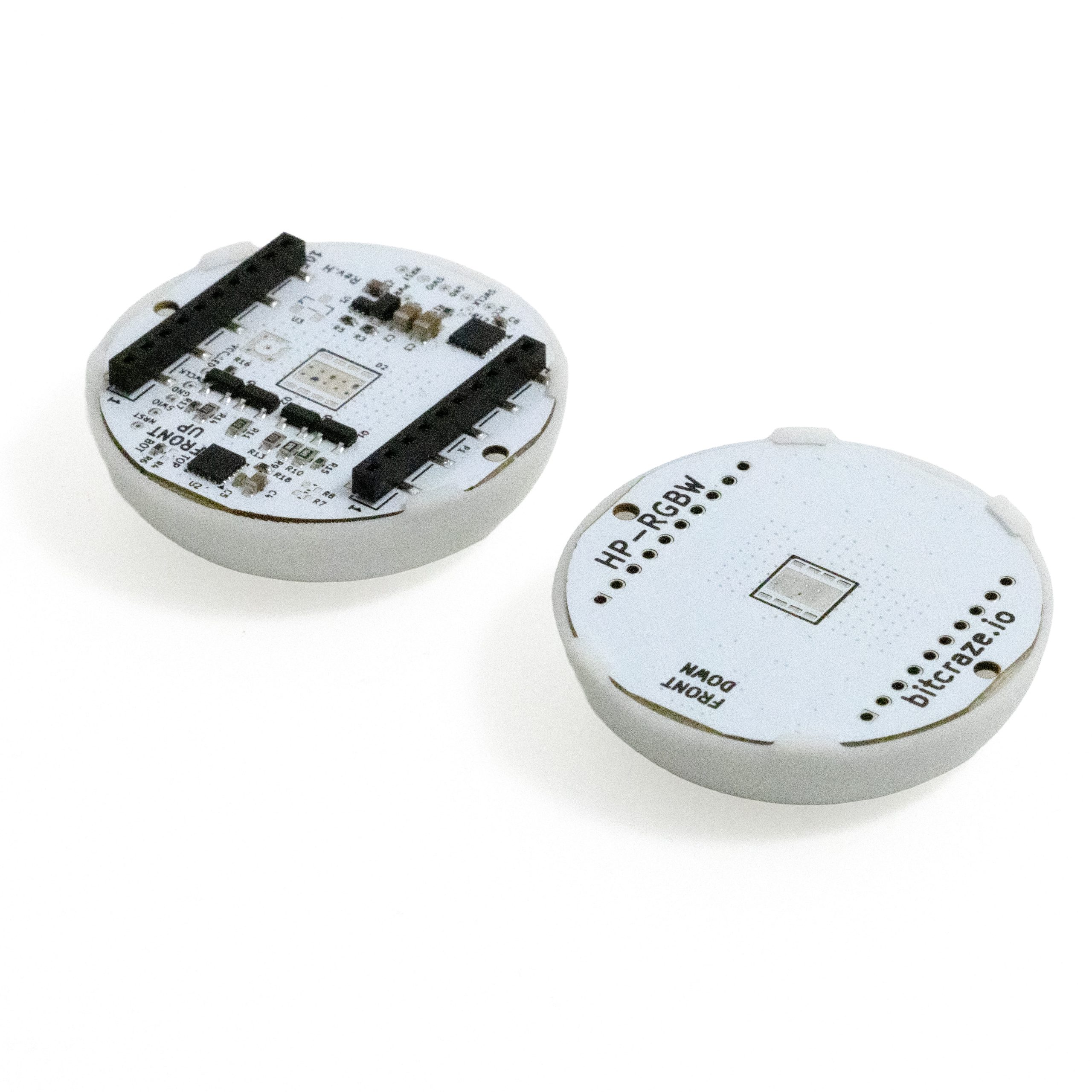
The CrazyflieTM Color LED deck is a high-powered, fully programmable RGB(W) lighting expansion for the Crazyflie 2.x platform —and it’s now available in the shop.
It delivers bright, diffused, and uniform light suitable for research, teaching, vision experiments, and indoor drone choreography. The deck mounts on top or bottom of the Crazyflie and integrates seamlessly through our open-source firmware and I²C-based deck interface.
Two Versions, Same Electronics
The Color LED deck is available in two distinct versions, each sold as a separate product.
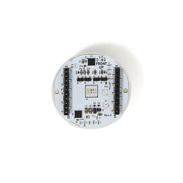
Top-Mounted Color LED Deck
Designed to be placed on top of the Crazyflie. Ideal for scenarios where the drone is viewed from above or when customers need to use positioning or sensor decks underneath the Crazyflie—such as the Flow Deck or other bottom-mounted modules.
Works well with motion capture (MoCap) systems using ceiling-mounted cameras.
Not recommended with the Lighthouse positioning deck, due to optical occlusion and interference with the lighthouse sensors.
You can find the top-mounted version in the store here
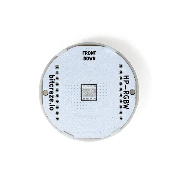
Bottom-Mounted Color LED Deck
This version is suitable for almost all use cases, offering maximum visibility from below and minimal interference with other decks.
Ideal for Lighthouse positioning (no optical obstruction).
Ideal for MoCap positioning, especially when cameras view from multiple angles
You can find the bottom-mounted version in the store here.
Dual Mounting for Maximum Visibility
Additionally, two Color LED decks can be mounted both above and underneath the Crazyflie simultaneously, creating a strong, uniform light signature visible from all directions. This is best for MoCap environments where multi-angle visibility improves marker/camera performance.
You can see all three variants of the Color LED in action in our latest Christmas video, created in collaboration with Learning Systems and Robotics Lab :
Each color LED deck variant operates independently, allowing the top and bottom decks to be configured with different colors if desired. While all variants share the same electronics, diffuser, and firmware behavior, their physical mounting positions let you choose the setup that best fits your lab, show environment, or positioning needs.
Diffuser now available
While designing the Color LED deck, we also created a light diffuser—now available in the shop to buy as a standalone product. It is designed to be compatible with the LED ring to spread and soften the light, extending visibility and improving appearance.
You can find the light diffuser in the store here.
The Color LED deck is available now in both versions. Head to the store to order, or contact us for a quote!
Today, we rejoin with Maurice Zemp who presented his work in an earlier blogpost.
Road to the Finals
I had officially completed my Matura thesis in October 2024 and submitted it to the Schweizer Jugend forscht competition. When I was selected for the semifinals, I was given the chance to present my work in front of a jury. Their feedback was highly constructive and came with clear requirements: for the finals, I would need to provide more in-depth analyses of the individual system components of my project. At first, this felt like a challenge, but in the process I realized how much these refinements elevated my research. By the time the finals approached, I felt both nervous and proud, knowing that the work I would present had grown far beyond the version I had initially submitted. On April 24, 2025, the big moment finally arrived – the start of the national finals.
Fig. 8: The Location of the semifinals
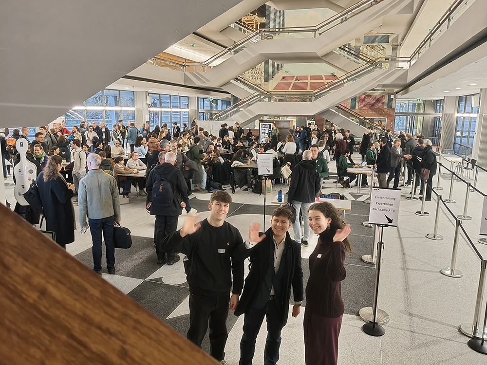
Day 1
The day began with my journey to ETH Zurich. Traveling by public transport, I carried my Crazyflie drone and the racing gate with me – equipment that had accompanied me throughout countless hours of development and testing and with which I wanted to make the comprehension of my project a bit more feasible. Arriving at ETH, I was greeted warmly at the reception, where I first felt a sense of belonging among dozens of passionate and curious young scientists.
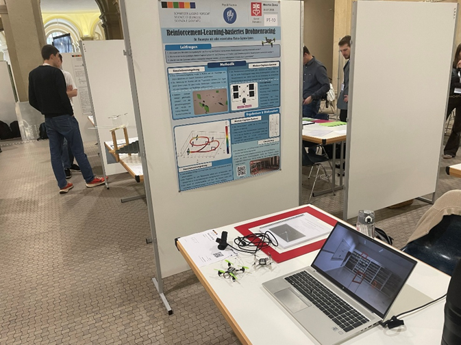
Fig. 9: My booth at ETH
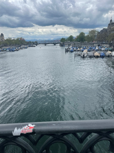
The morning was dedicated to setting up our booths. Piece by piece, the exhibition hall transformed into a vibrant space filled with prototypes, posters, and creative ideas. Once my own stand was ready, I finally had a moment to take in the atmosphere and to start the first conversations. In the afternoon, we were treated to a guided city tour through Zurich. Walking through the old streets, hearing stories about the city, and enjoying the fresh air was the perfect opportunity to get to know the other participants better.
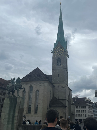
Fig. 10: The Limmat (River in Zurich)Fig. 11: The Grossmünster church in Zurich
Later that day, alumni of Schweizer Jugend forscht visited the exhibition. For the first time, I had the chance to present my project outside of the jury context, and I was surprised by the interest and thoughtful questions I received.
By the time we arrived at our youth hostel late in the evening, the excitement of the day had fully caught up with me. Exhausted but exhilarated, I fell into bed.
Day 2
The second day began with breakfast at the youth hostel, followed by a short tram ride back to ETH Zurich. The morning program was dedicated to the jury sessions, which represented one of the most important parts of the entire competition. Unlike in the semifinals, where I just explained my project and was asked some general questions, this time I was able to discuss my project in detail with several experts – including those specializing in fields beyond my own topic.
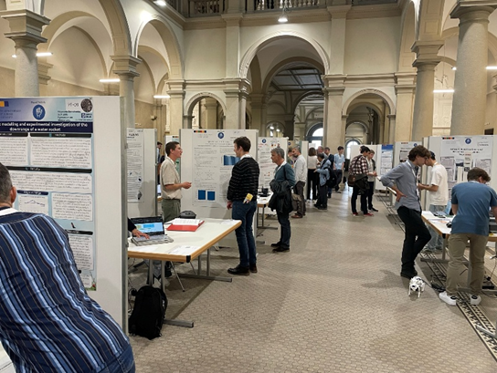
Fig. 12: The ETH Main Hall filled with interesting projects
These conversations quickly turned into fascinating discussions. The jurors asked insightful questions, challenged certain assumptions, and encouraged me to think more deeply about the potential applications of my work. At the same time, I received a great deal of praise, which was both reassuring and motivating. It was incredibly rewarding to see that months of effort, refinement, and problem-solving were being recognized by experienced professionals.
In the afternoon, the doors of ETH opened to the public for the exhibition. Friends, family members, and curious visitors from outside the competition came to explore the stands. Presenting my project in this setting felt very different from the formal jury discussions of the morning – it was more relaxed, conversational, and filled with spontaneous questions. I especially enjoyed seeing how people unfamiliar with drone technology reacted to the project, and it gave me the chance to practice explaining complex ideas in a way that was accessible to everyone. After such a full day of interactions, we returned to the youth hostel in the evening. The atmosphere there was much calmer, as everyone tried to recharge a little energy in preparation for the final day.
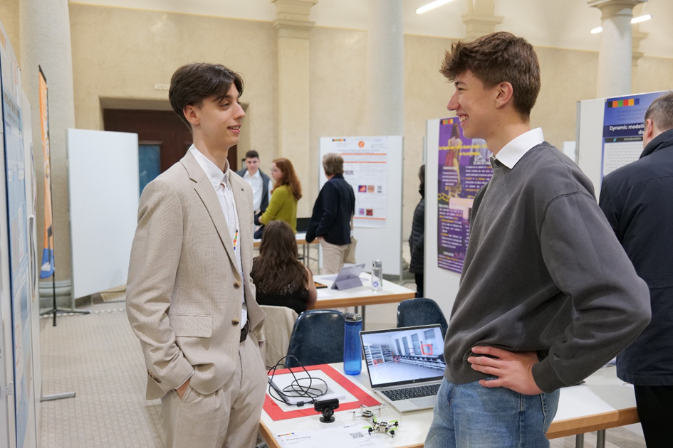
Fig. 13: Me explaining my project to a friend of mine who came to visit me
Day 3
The final day once again began with our journey to ETH Zurich. In the morning, the exhibition hall opened its doors for a second round of public visits. This time, the experience was especially meaningful for me, as my family came to see my project in person.
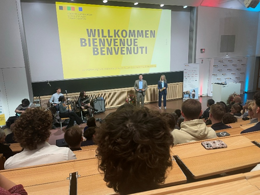
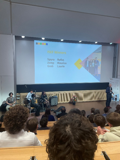
After lunch, it was finally time for the highlight of the competition: the award ceremony. A live band set the stage, and soon the opening speeches began. The tension in the room was almost tangible – every participant knew that months, if not years, of work were culminating in this single event. I felt both nervous and excited, my heart beating faster with each passing moment.
Fig. 14: The start of the award ceremonyFig. 15: My nomination to ISEF 2026!
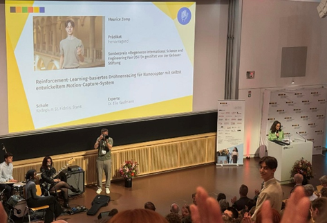
Then came an unexpected twist: even before the regular prizes and certificates were announced, the jury revealed the winners of the most prestigious special awards. To my immense joy, my name was called. I had been selected to represent Switzerland at the International Science and Engineering Fair (ISEF) 2026 in Phoenix, Arizona. The sense of relief, excitement, and pride I felt in that moment is difficult to describe – it was a dream come true.
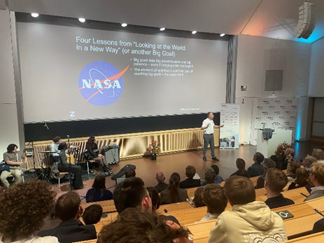
The ceremony continued with an inspiring keynote by former NASA Director Thomas Zurbuchen, who shared his journey in science and reminded us of the importance of perseverance and never giving up.
Fig. 16: An inspring talk by Thomas ZurbuchenFig. 17: Me being awarded my distinction
Finally, the time came for the official certificates. One by one, every participant was called to receive their recognition. When my turn came, I was awarded the highest possible distinction: hervorragend (outstanding) honored with CHF 1500. The applause and congratulations that followed made the moment even more unforgettable.
The evening concluded with an apéro, where I had the chance to exchange thoughts with professors, fellow participants, and many guests. I was overwhelmed by the warm words of encouragement and congratulations I received for both my project and the recognition it had achieved.
After three exciting, inspiring, and at times exhausting days, it was finally time to return home – this time together with my parents, carrying not only my luggage but also an experience that I will cherish for a lifetime.
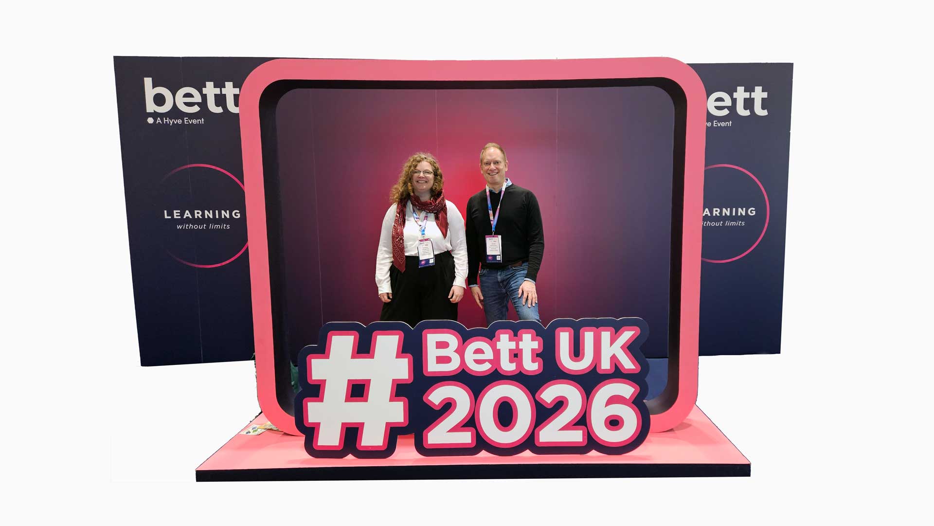
Last week, Bitcraze attended the BETT Show in London to get a better sense of how the education landscape is evolving.
BETT (British Educational Technology Show) brings together educators, edtech companies, curriculum developers, policymakers, and technology providers across the full spectrum of learning: from primary school to higher education and professional training.
For us, it was a valuable opportunity to listen and get an understanding of where the general EDU landscape is and where it is heading.
Meeting Familiar Faces, and New Ones
One of the most rewarding parts of the visit was reconnecting with existing partners already using the CrazyflieTM in educational settings, and meeting new potential collaborators: teachers building robotics programs, universities modernising their lab infrastructure, and organisations developing national STEM (Science, Technology, Engineering, and Mathematics) and STEAM (Science, Technology, Engineering, Art, and Mathematics) initiatives.
A recurring theme in many conversations was the need for platforms that are robust and safe to use in classrooms, scale from simple programming exercises to advanced autonomy and AI, support both structured teaching and open-ended experimentation, and are well documented (both for the teacher and for the student).
These are exactly the problems we have spent more than a decade working on.
What the Education Robotics Market Looks Like Today
Speaking with a wide range of robotics vendors, software providers, and solution integrators gave us a clearer picture of the realities of the K-12 and STEM market:
Procurement is often tender-based and highly structured
Budgets are tight and price sensitivity is real
There are many vendors offering similar-looking robotics kits
Hardware is physically robust and classroom-proof and safety is critical
Programming is dominated by Python, Scratch, Blockly, or proprietary visual tools
“AI-enabled” frequently means GPT-style programming blocks layered on top
LEGO compatibility is everywhere
micro:bit has effectively become a compelling entry-level control board
Buyers apply hard scrutiny to educational value and learning outcomes
Real adoption requires curricula, lesson plans, and teacher training programs
And in practice, U.S.-developed curricula often transfer reasonably well globally
Why the Crazyflie is a Great Fit for Education
Although the Crazyflie originated as a research platform, its characteristics map naturally to education:
STEM / STEAM (Upper Secondary & High School)
Students can work hands-on with control systems, sensors, wireless communication, programming, and basic AI in a physical system they can see, debug, and iterate on. It makes abstract concepts tangible.
Undergraduate Education
Crazyflie is increasingly used in robotics, embedded systems, and mechatronics courses to teach estimation, control, perception, and multi-agent systems without the overhead of large and expensive hardware.
Post-graduate Research
This remains our strongest domain: swarm robotics, learning-based control, human–robot interaction, indoor navigation, and distributed systems.
The continuity matters. Students don’t outgrow the platform. They grow with it. And, more importantly, the same openness that researchers value is increasingly relevant in education as well (particularly relevant in the light of recent geopolitical movements). Institutions want transparency, long-term maintainability, and the freedom to adapt tools to their pedagogy and not just consume closed kits.
Education is a Strategic Part of the Robotics Ecosystem
BETT confirmed that education is a strategic and structured part of the robotics ecosystem. Not just as “learning about robots”, but as a way to train future engineers, researchers, and system designers using realistic platforms from an early age.
Succeeding in this segment requires more than good hardware. It requires thoughtful packaging, clear educational positioning, proper teaching material, partner ecosystems, and long-term commitment.
To those we met at BETT, thank you for the conversations. And if you are working with STEM, STEAM, or robotics education and are curious about the Crazyflie, we are always happy to talk.
Today, we welcome our first blog post by Maurice Zemp. Stay tuned for more of his adventures later!
When I started working on my Matura thesis (a mandatory project in Swiss High School), I wanted to create something that went beyond a purely theoretical project. I was fascinated by the idea of combining cutting-edge technology with a very tangible and exciting challenge: making a small drone fly through a racing course, composed by small gates, completely on its own and as fast as possible. Inspired by the work under Prof. Davide Scaramuzza, I set off for a challenge to find some new alternatives or improvements, while developping my approach from scratch.
What may sound simple at first quickly turns into a highly complex task. A drone needs to perceive its environment, process information in real time, and decide on precise actions within fractions of a second, all without human intervention. Professional drone racing pilots train for years to master this level of control. My goal was to see whether artificial intelligence could achieve something similar, using reinforcement learning as the core technique.
But there was another challenge: I wanted to design a system that wasn’t only powerful, but also affordable and reproducible. Many research institutions use equipment worth tens of thousands of francs for projects like these. I asked myself: Could I build something comparable with a fraction of the budget, and still push the boundaries of what’s possible?
That question became the driving force behind my project, which later brought me all the way to the finals of Schweizer Jugend forscht (short SJf) and saved me a place as the main prize to represent Switzerland at the world’s biggest Youth Science Competition, ISEF 2026. Over the following sections, I’ll share how I built my system step by step, what it was like to present it at the competition, and how it felt when all the effort finally paid off.
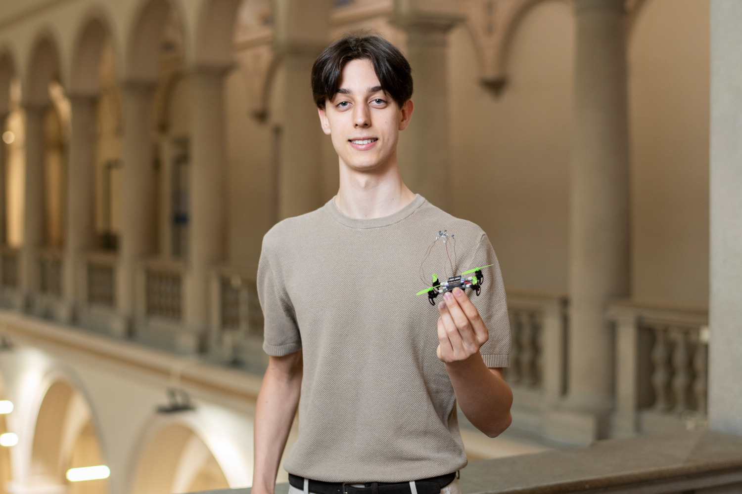
Fig. 1: Me with the Crazyflie 2.1 Brushless in the halls of ETH Zurich, where the main event of SJf took place.
Motivation and Objectives
The project I presented at Schweizer Jugend forscht was the result of my Matura thesis, in which I set out to combine my interests in drones, programming, and artificial intelligence. My goal was to develop a complete system for autonomous drone racing, based on Reinforcement Learning (RL), that would not only work in simulation but could also be transferred to real-world conditions.
To achieve this, I focused on three key aspects:
Building a highly efficient simulation environment for training a reinforcement learning agent.
Developing a cost-effective motion-capture system (MoCap) capable of tracking a drone’s position and orientation in real time with high precision.
Integrating both systems in a way that would allow seamless transfer from simulation to real-world experiments with minimal latency.
This combination made the project unique: instead of relying on expensive commercial hardware, I set out to create a solution that would be precise and affordable but still continue the state-of-the-art development in Drone Racing.
Simulation Environment
The simulation was implemented in Python, using Stable Baselines, OpenAI Gymnasium, and NumPy, accelerated with Numba for performance. At its core, the system employed the Proximal Policy Optimization (PPO) algorithm, a state-of-the-art reinforcement learning algorithm known for stability and efficiency.
Unlike general-purpose simulators such as Gazebo, my environment was designed specifically for drone racing. It could process tens of thousands of interactions per second, enabling a training run of a few dozen minutes to correspond to nearly a year of simulated flight time.
Key features included:
A physics-based flight dynamics model accounting for thrust, drag and gyroscopic effects.
A carefully engineered reward function balancing speed, precision and avoiding shortcuts.
A flexible design that allowed different gate sequences and drone parameters to be tested.
A multi-agent environment computing on multiple threads, leading to much shorter training time needed.
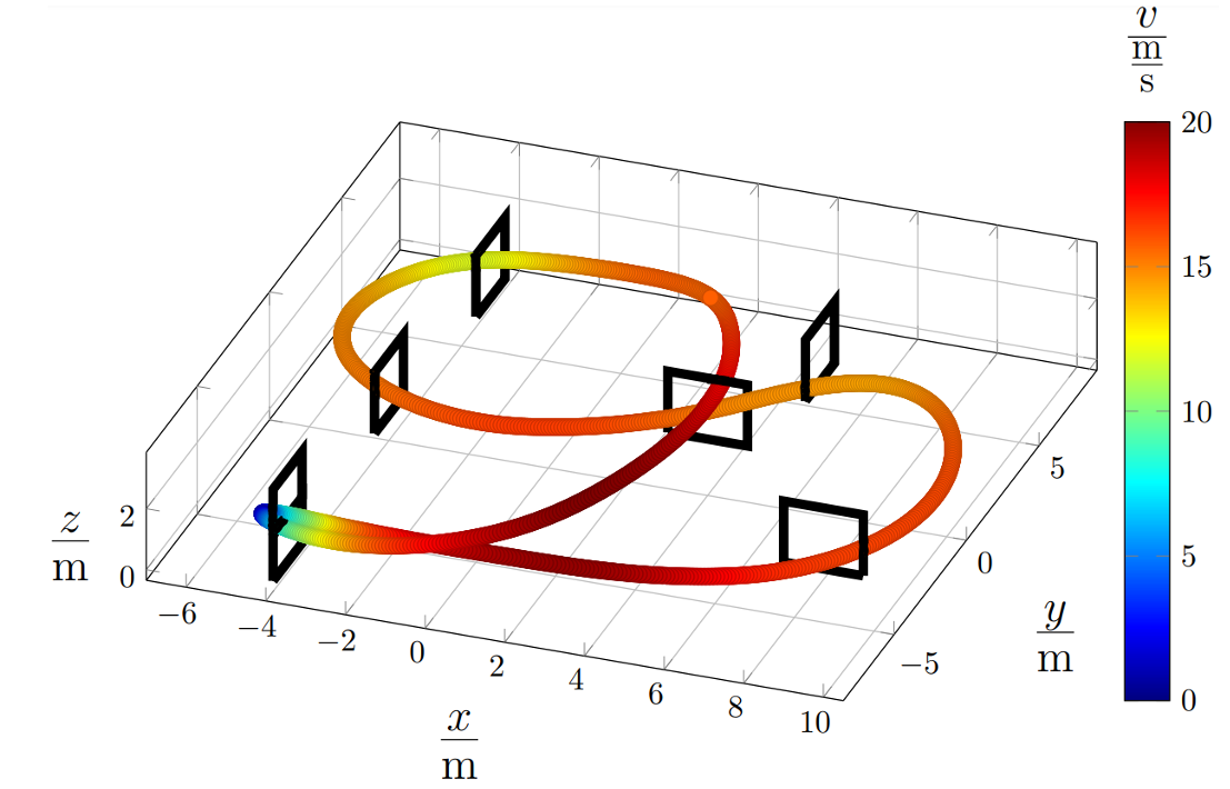
Fig. 2: Path of the drone after two hours of training on a given track
With this setup, an RL agent could learn to complete arbitrary racing tracks in near-optimal time1 after only a few hours of training. In simulation, top speeds of up to 100 km/h were achieved, though these exceeded the physical limits of the real drone and were generated with modified drone parameters.
Motion-Capture-System
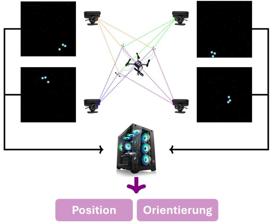
A second cornerstone of the project was the development of a low-cost motion-capture system. Instead of relying on high-end solutions such as VICON or OptiTrack (which can cost tens of thousands of Swiss francs), I built a custom setup. The drone – a Crazyflie 2.1 Nanocopter (later a Crazyflie 2.1 Brushless) – was fitted with infrared diodes. With four cameras capturing at 120 frames per second, the drone’s position was calculated in real time through triangulation. By using three diodes arranged on the drone, I not only wanted to estimate the position but also the orientation. Unfortunately, due to the cameras being budget and thus not having a high-end resolution, the estimation of the orientation was not feasible and was therefore taken from the onboard IMU.
Fig. 3: Motion-Capture-System Concept
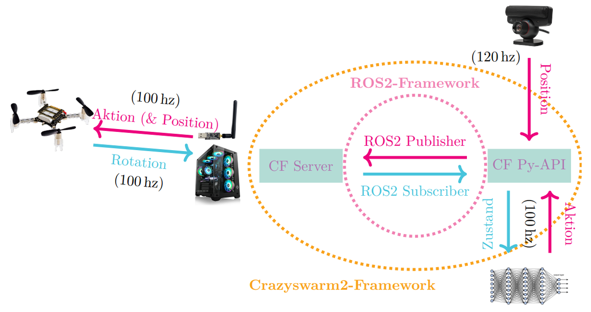
System Integration
For integration, I relied on the ROS2 middleware and the Crazyswarm2 framework, which allowed the simulation and MoCap data to be processed together with minimal latency. This setup ensured that a policy trained in simulation could be executed on the real drone almost seamlessly.
Fig. 4: Sim2Real Integration Concept
Results & Discussion
The results demonstrated the effectiveness of the combined system:
In simulation, the RL agent completed tracks in nearly optimal time1, demonstrating robust generalization across different gate sequences.
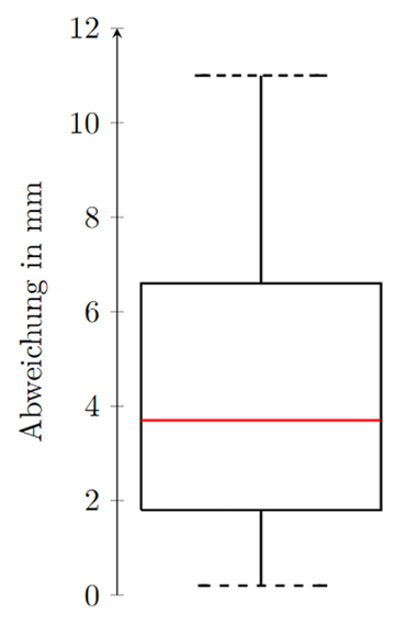
The motion-capture system delivered millimeter-level accuracy and reliable tracking in real time despite its simplicity. (see Fig. 5)
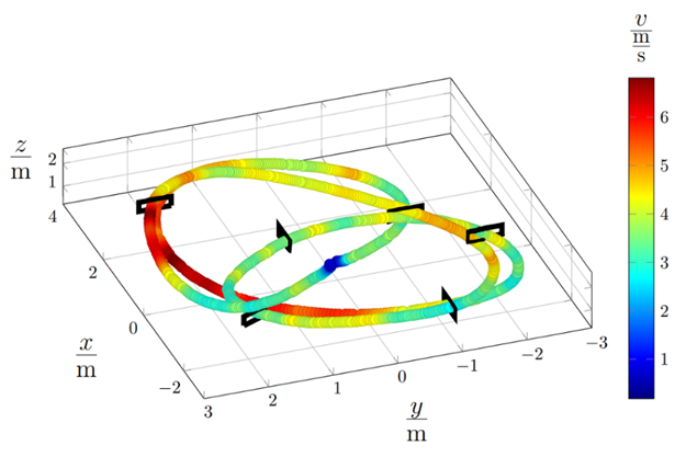
In real-world tests, the Crazyflie drone successfully completed tight gate sequences, even at speeds of up to 25 km/h, with a positional deviation of only 5–12 cm compared to the simulated trajectories. (see Fig. 6)
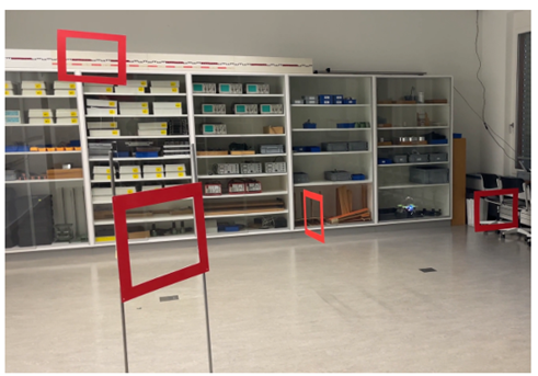
Given that the gates were roughly A3-sized openings (38 × 29 cm), the precision was sufficient to consistently hit every gate, confirming the feasibility of transferring simulated training into real-world racing. (Video)
Fig. 5: Boxplot of the deviation for collected points on a plane in millimeters
Fig. 6: Tracked Real Life Path on a given trackFig. 7: Realisation in my school’s physics laboratory
The system demonstrated that RL-based controllers can generalize effectively from simulation to reality, even with imperfect models. This robustness shows that RL is promising for real-world robotics applications where exact physical modeling is difficult or costly. To further investigate this robustness, I conducted ablation studies in simulation focusing on aerodynamic drag, as well as analyses of the MoCap system’s accuracy in measuring dynamic motion.
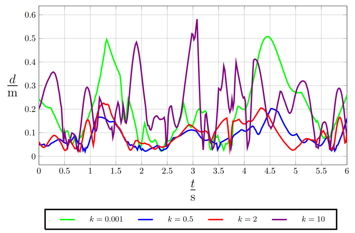
As for the aerodynamic drag, I introduced some randomness during evaluation, which deviated largely from what the Algorithm had trained upon. To achieve this, I introduced a parameter k which was multiplied with the correct aerodynamic drag to view how these differences would impact the flight. In Fig. 8 you can see the deviation from the real path over the course of a flight. As obviously more drag results in lower velocities, the two paths had to be fitted using the nearest two possible points. The results are impressive, even with an enormous change to training such as k = 10 the flight still performed somewhat okay, even though the gates probably wouldn’t have been hit anymore.
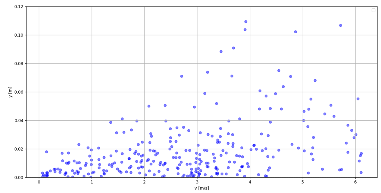
For the MoCap System, I used a mathematically representable motion, such as a pendulum. Then I performed a parameter optimization on this mathematical model and measured the deviation based on the current speed. There is a clear correlation between speed and deviation (see Fig. 9), which most likely was caused by the missing calibration of the cameras.
Fig. 8: Results of ablation studies on aerodynamic dragFig. 9: Experiment to confirm correlation between deviation and speed
Conclusion and Reflection
This work demonstrates that RL, combined with accessible hardware, enables precise and robust autonomous flight in dynamic indoor environments. The results underscore the potential of low- cost robotics solutions to democratize drone research. Even though it was a large project and there were some hard times, I enjoyed working on it a lot and believe that the result and the memories made with it are even more rewarding than any prize money!
Acknowledgments
To end this guest post, I want to sincerely thank Bitcraze for their amazing work and support during the development of this project. They have genuinely built such an incredible testbed for research in autonomous drones, it’s amazing! Without them, this project wouldn’t have worked out the way it did!
Near-optimal time here references to the theoretical boundary of a drone completing this track, given it’s parameters. To be clear, this is not fitting a polynomial with boundaries on their derivatives onto gate segments, as it was done during earlier approches in the 2010s. It was compared to multiple previous approches by UZH RPG such as Optimal Control (OC). Nevertheless, this comparison could be done more extensively in the future, as time ran short in the end. ↩︎
Since the end of 2024, we’ve been putting effort into spreading out our manufacturing. With international trade rules rapidly changing, it felt like the right moment to expand our production footprint. Doing this helps us keep stock more stable, react faster to demand, and makes life easier for you when it comes to potential import-related costs.
To make it happen, we’ve been working closely with our long-time partner in China, Seeed Studio. They’ve been helping us move the production of some of our items to Vietnam, where exciting new opportunities have opened up. This way, we can keep the same quality and reliability you’re used to while spreading out production across more locations, which makes our supply chain stronger.
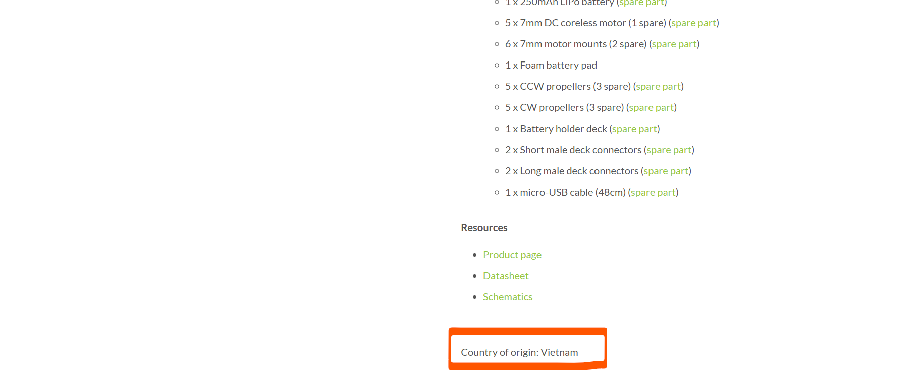
Right now, four of our products are being made in Vietnam: the Crazyflie 2.1+, the Crazyflie 2.1 Brushless, the Flow Deck, and the Crazyradio 2.0. Meanwhile, the Charging Dock is made here in Sweden, and the Lighthouse Base Station comes from Taiwan. That means our production is now spread over four different locations!
We still produce in China as well—that’s where our newest deck will come from, for example. The plan is to gradually add more products made in Vietnam, spreading production across locations, reduce risk, and keep things running smoothly for both us and you. Over time, this will make it easier to maintain stock, respond quickly to demand, and give you a smoother experience no matter where you are in the world.
We also want to make it visible where your products come from when you shop with us. In May, we updated the store to clearly display the country of origin for each item. You can now find this information at the bottom of every product page, so you always know where the item in your cart is being made. For many of you, this small detail helps plan ahead and makes it easier to estimate any extra costs from international shipping.