First of all, happy new year on behalf of the Bitcraze team. In this post we would like to talk about the Deck API, but first a little bit of background.
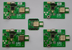
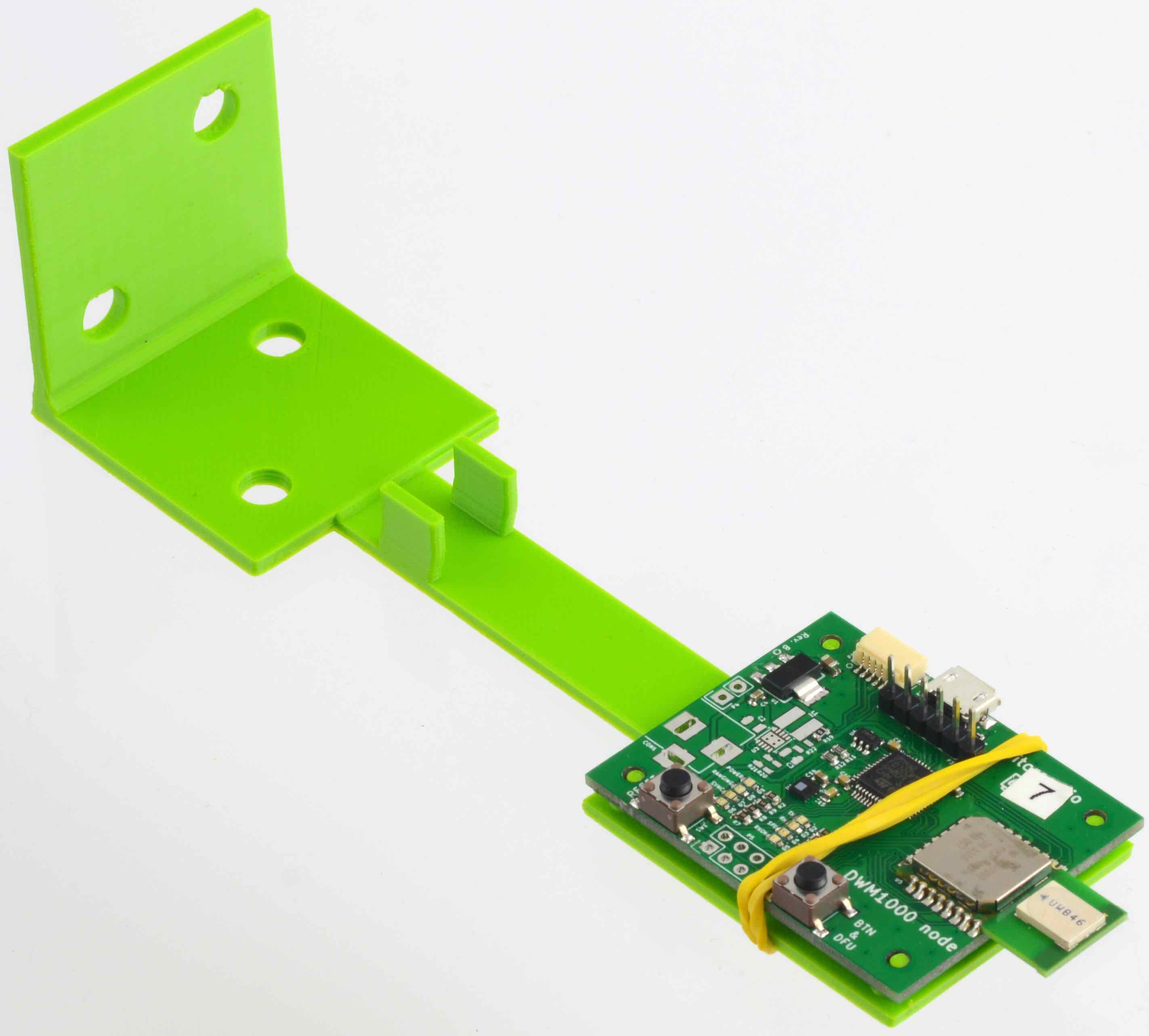
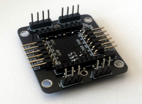
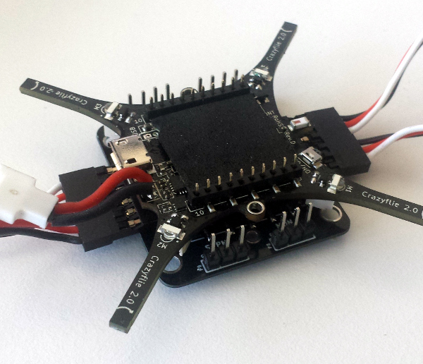
Crazyflie and pretty much all we do is open-source. The main reason is that we want to share and allow everyone to build upon what we are doing. The first Crazyflie was expendable with an expansion port but modifying it was hard because it required good soldering skills. However if we really want others to build and use what we do, we had to increase the usability. So, when designing Crazyflie 2.0 we put a lot of efforts into making it easily expendable. We ended up with the deck port, which makes it easily to add an expansion board, called a deck, on top or bottom of the Crazyflie 2.0. An installed deck will automatically be detected and initialized when the Crazyflie starts thanks to the one-wire memory they contain. Finally we have also made the breakout and prototype deck to help making new decks.

With all this, we believe we managed to make it much easier to create a new deck. However making the firmware driver for these decks still required to understand a lot about how our firmware is architectured. It also did require to add code to multiple files to ensure the driver runs properly. The new deck API aims at making the firmware driver development more straightforward.
The base of the deck API is the driver declaration: it is possible to add a deck driver without having to modify any code in the firmware. The driver just has to be compiled and it will be automatically loaded at Crazyflie startup. This is inspired by the way the Linux kernel is loading modules and drivers. So the minimal driver can be written in 12 lines of code:
#define DEBUG_MODULE "HelloDeck"
#include "debug.h"
#include "deck.h"

/* init function */
static void helloInit()
{
 DEBUG_PRINT("Hello Crazyflie 2.0 deck world!\n");
}

/* Driver registration */
static const DeckDriver helloDriver = {
 .name = "myHello",
 .init = helloInit,
};
DECK_DRIVER(helloDriver);
In this example, the driver will be initialized automatically if a deck is installed with the name “myHello”. It is also possible to force the driver initialization. For more information there is a documentation for this on the wiki and there is also a short howto that will guides you from zero to having your code running in Crazyflie.
There is also an implementation of the digital and analog input/output API similar to Arduino.
There is a lot of work left on the deck API. Among other things:
- Easy shortcut to run tasks: currently the only way to run a task is to create one using the FreeRTOS API. The plan is to provide easy to use timers and an Arduino-like loop function.
- More drivers for SPI, Serial, I2C, …
- Access to other parts of the system like controlling the flight setpoint or setting the LEDs.
The two first are quite straightforward and ‘just’ need to be done. We are not so sure how to implement the last one yet (we need a good way to modularise the firmware). If you have any input on things you would like to see in the API please contact us, the forum is good for discussion and a ticket in the firmware github project for functionality. You are also welcome to help-out with the implementation, documentation or reporting bug :-).