The Crazyflie 2.0 supports two types of radio protocols out of the box: ESB (Enhanced ShockBurst) for Crazyradio/Crazyradio PA USB dongle compatibility and Bluetooth LE for mobile devices. All Crazyflie 2.0’s are shipped with a radio bootloader, able to update virtually all the different parts of the firmware running in Crazyflie 2.0. We thought we would do a post to explain a bit further how it all fits together. Even though the Crazyflie 2.0 supports Bluetooth LE, the preferred way is to use the Crazyradio/Crazyradio PA when doing development. Flying via Bluetooth is very practical since there’s no additional hardware needed except for a mobile device, but the Crazyradio/Crazyradio PA has minimal latency, more bandwidth and works easily with computer. This makes it ideal for development and other advanced usage.
(On a side note, some of our products are currently out of stock (like the Crazyradio PA and LED-ring). We have started the next batches, so they should arrive soon. Until then have a look at our distributor page to find our products.)
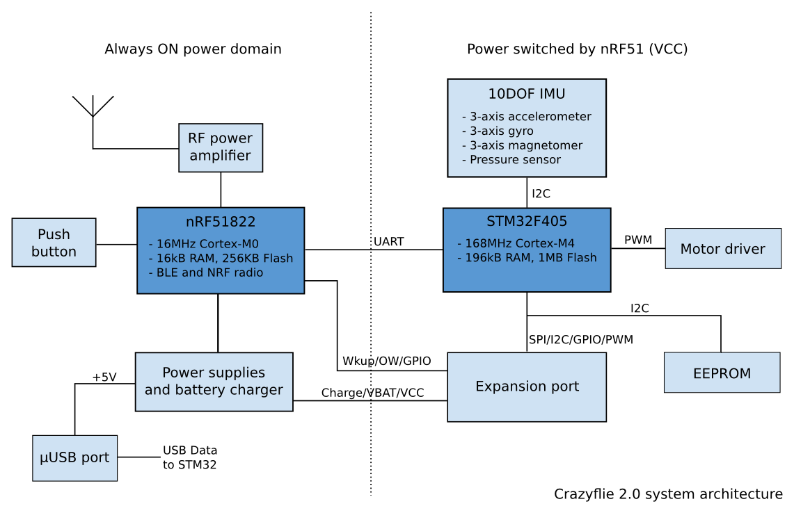
Crazyflie 2.0 architecture
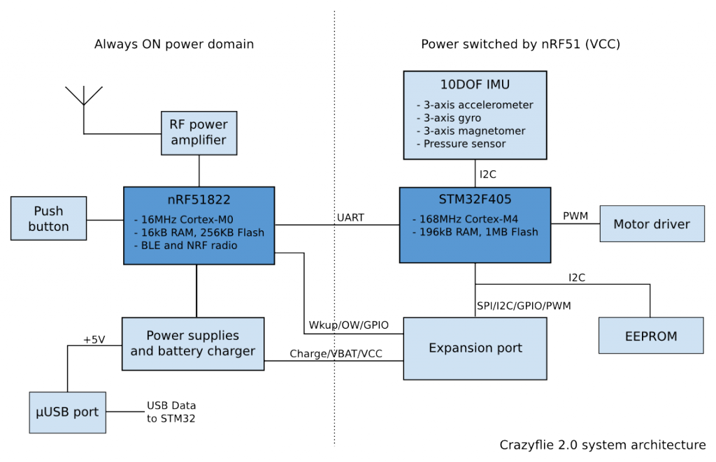
For the radio of Crazyflie 2.0 we choose the nRF51822. The great thing with this chip is that it integrates a radio compatible with our existing Crazyradio USB dongle as well as with Bluetooth Low Energy. The nRF51 also integrates an ARM Cortex-M0 MCU enabling radio protocols to be implemented directly in the chip. However this MCU is not powerful enough to be used by itself in our quadcopter development platform, so we put a powerful STM32F4 Cortex-M4 168MHz on the side to do the heavy work.
The nRF51 mainly handles radio and power management and the STM32F4 handles all the rest: flight control, expansion port, log, param, etc. As far as the radio is concerned the nRF51 act as a bridge: CRTP packets are received by the nRF51 and sent unmodified to the STM32F4 and the STM32F4 sends raw CRTP packets to the nRF51 that transmit it by the radio. This means that the STM32 firmware is unaware of the physical communication protocol, it can be Bluetooth, Shockburst or something else, it makes no difference it is still CRTP packets. CRTP is the protocol used to control Crazyflie, it encapsulates all commands and messages exchanged between the client and the Crazyflie.
Enhanced Shockburst (ESB)
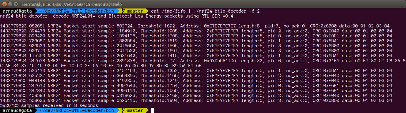
Enhanced Shockburst is a radio physical protocol implemented in some Nordic Semiconductor 2.4GHz radio chips. In the nRF24 chip, used by Crazyradio (PA) and the original Crazyflie, this protocol is implemented in hardware and we have little control over it. The nRF51 used in Crazyflie 2.0 offers more control on the radio physical packet and ESB since it’s implemented in software instead.
ESB handles ack and retries: The Crazyradio sends a packet on a given channel and waits for an ack. If a Crazyflie receives the packet without error it sends an ack packet. If an ack is received, the Crazyradio can send the next packet. If no ack is received Crazyradio will automatically retry by sending the same packet again. The current implementation will retry to send a packet forever, so all packet are guaranteed to be transmitted as long as a Crazyflie is in range. Packets are sent back by the Crazyflie by adding a data payload to the ack packet. Close to 80 different channel can be used and every packet is sent with an access address, so more than one Crazyflie could share the same channel.
Enhanced Shockburst using the Crazyradio (PA) offers the lowest latency that can be expected. The minimum latency to send a packet is estimated to about 2ms (1ms minimum for USB and 1ms measured latency for the radio at 2Mbps without any retries). With the Crazyflie 2.0 and the Crazyradio PA it also offers the maximum range with 20dBm power output.
For the original Crazyflie there is an implementation of the E-sky RC transmitter protocol. This permits controlling the Crazyflie directly from an RC transmitter. It is technically possible to implement this protocol in the Crazyflie 2.0 nRF51, but it hasn’t been done yet.
Bluetooth Low Energy
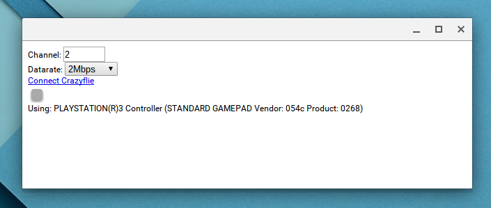
In the Crazyflie 2.0 Bluetooth low energy is implemented as a CRTP bridge: CRTP packet are written and read using Bluetooth. This simplifies greatly the implementation, but does not make full use of the Bluetooth LE functionality. It is planned to add more Bluetooth capabilities for things like communicating the battery status and being able to switch ON or OFF the Crazyflie with a mobile devices.
On the nRF51 side the Bluetooth functionality is implemented using the Nordic Semiconductor S110 Bluetooth stack. This stack runs independently of the firmware. Nordic calls this a softdevice and it’s a fitting description of how it works. It almost looks like a hardware device from the firmware point of view as it is not linked into the main firmware.
However we do not currently have the right to distribute the supporting files for the stack, so unfortunately you will have to download them yourself if you want to compile your own nRF51 Bluetooth firmware. To do so you must own a Nordic Semiconductor development kit. Even though some of the kits are pretty cheap, we do not like this situation at all so we are working on solving it. However we made sure that it is possible to compile the nmRF51 firmware without Bluetooth, to avoid the added dependencies. This means that you can still build your own nRF51 firmware to work with a Crazyradio/Crazyradio PA.
Bootloader/firmware upgrade
The Crazyflie 2.0, like the original Crazyflie, is upgradable wirelessly with radio. The radio bootloader has been enhanced to work both with ESB and Bluetooth LE. Both nRF51 and STM32F4 can be upgraded and it is even possible to upgrade the nRF51 Bluetooth stack and bootloader.
Currently the bootloader is working with Crazyradio on ESB. Bluetooth implementation for iPhone and Android is still work in progress. The STM32F4 can also be upgraded via USB and so, for people that does not have a Crazyradio, the first Crazyflie 2.0 firmware upgrade has been released for USB DFU as well as the classical radio bootloader update package.