If you’ve spent any time exploring the Crazyflie® ecosystem, you’ve probably noticed that almost everything is out in the open. The firmware is public. The communication protocols are documented. Development tools, client libraries and documentation all live in public repositories.
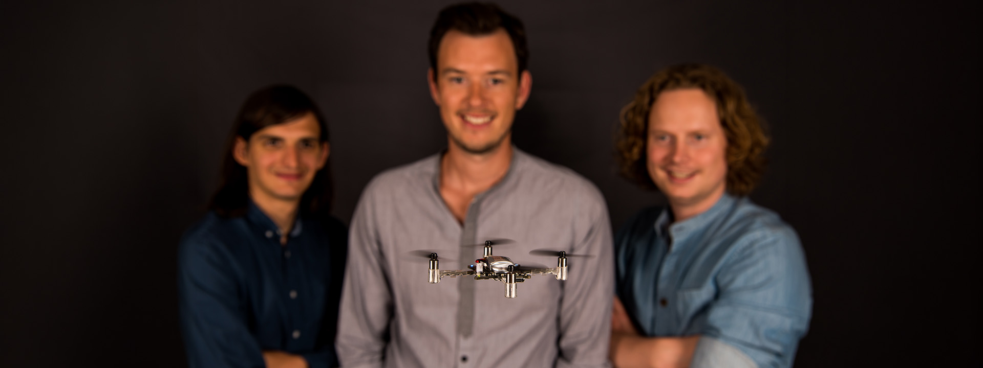
That’s not an accident, and it wasn’t the result of a carefully crafted business strategy. It started with three engineers trying to solve an interesting technical problem.
A project built for curiosity
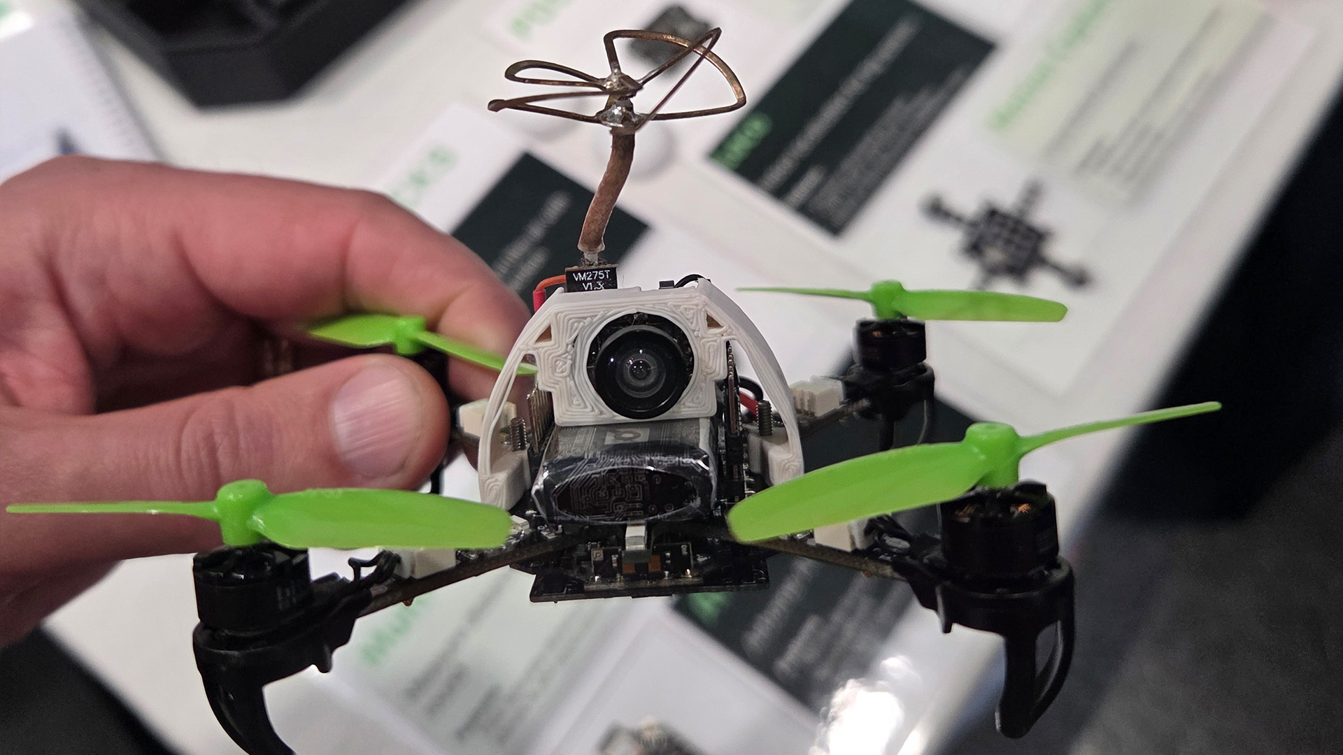
The Crazyflie started as an engineering challenge: build a very small quadcopter that could fly indoors. That sounds simple now, but the constraints were severe. Weight mattered. Power mattered. Every component had to justify its place. The printed circuit board was not just electronics; it became part of the structure of the aircraft.
From the beginning, the project was shaped by curiosity rather than product planning. The point was not only to make something fly. It was to understand how it could fly.
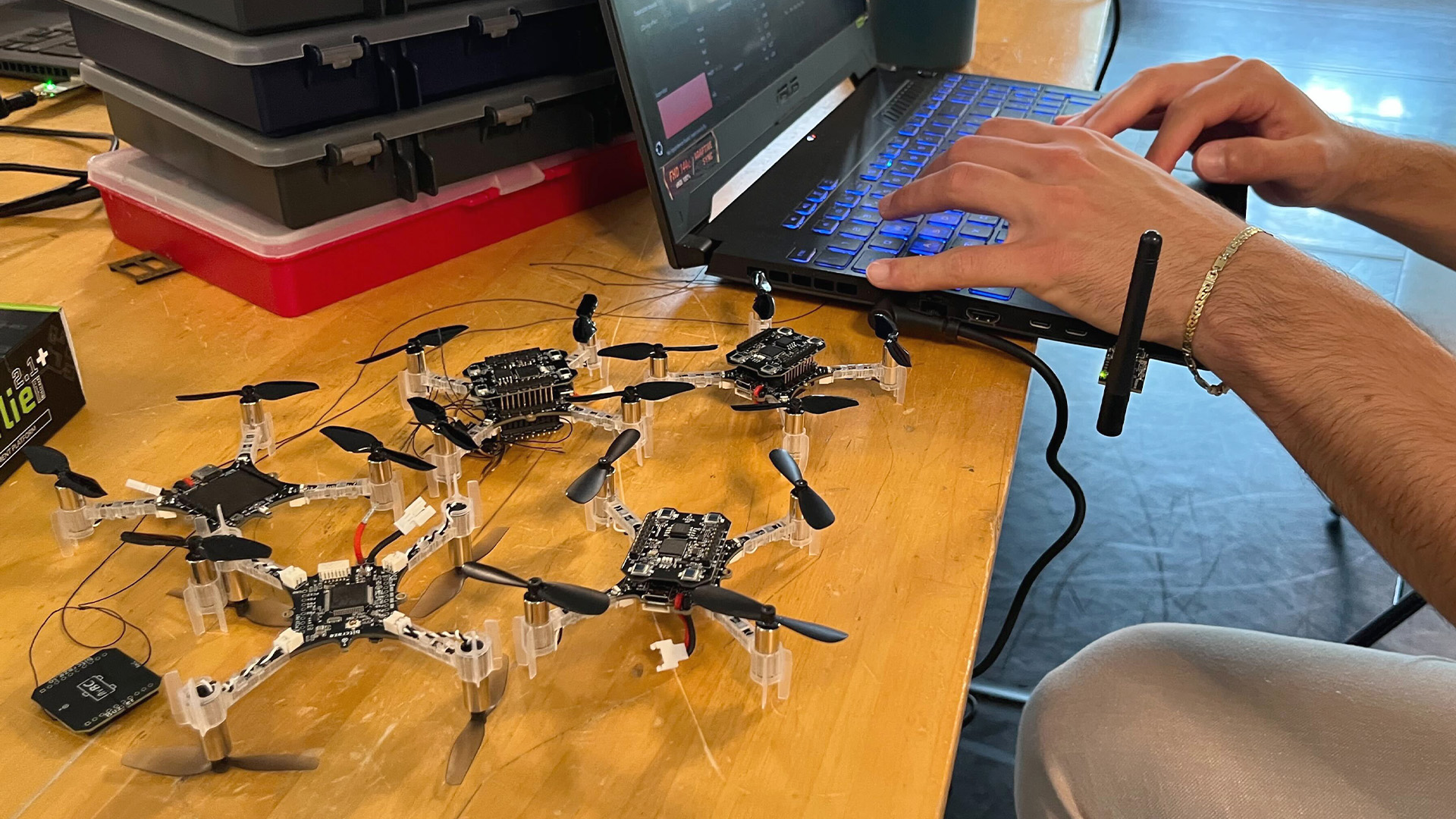
When the early work was shared publicly, people were not only interested in the result. They wanted to understand the system. They wanted to inspect the code, study the design, modify the firmware and try their own ideas, and that response mattered. It showed that the real value of the Crazyflie was not simply that it was small. The value was that it could become a platform for people who wanted to learn, experiment and build.
Openness as an engineering principle
For engineers, openness has always been practical before it was philosophical. If you’re trying to understand why a controller behaves a certain way, you need to read the code. If you’re developing a new positioning algorithm, you need to understand how measurements flow through the estimator. If you’re integrating new hardware, you need documentation instead of guesswork.
This is why openness made sense for Crazyflie from the start. The intended users were not passive operators. They were researchers, students, developers and hardware-oriented innovators. For them, the ability to inspect and modify the system was not a bonus feature. It was part of the reason to use the platform at all.
That remains one of the clearest differences between a development platform and a finished consumer product. A consumer product tries to hide complexity. A development platform must expose enough of the system for serious users to understand and change it.
What “open” means in a Crazyflie context
The word “open” can become vague if it is not defined. For Bitcraze, openness does not mean that every part of the company, every internal process or every commercial asset is unrestricted. It means that the Crazyflie ecosystem is designed to be inspectable, modifiable and extendable in the areas that matter most to users.
Firmware is open source. Software libraries are open source. Communication protocols are openly documented. Development tools are public. Documentation is public.
Hardware follows a slightly different model. Schematics, board designs and technical documentation are published to help users understand, integrate and extend the platform, while Bitcraze also maintains the commercial foundations required to continue designing, manufacturing and supporting new hardware. That distinction is deliberate.
Why are there boundaries?
Openness is not without trade-offs, though, and every engineering decision involves balancing competing goals.
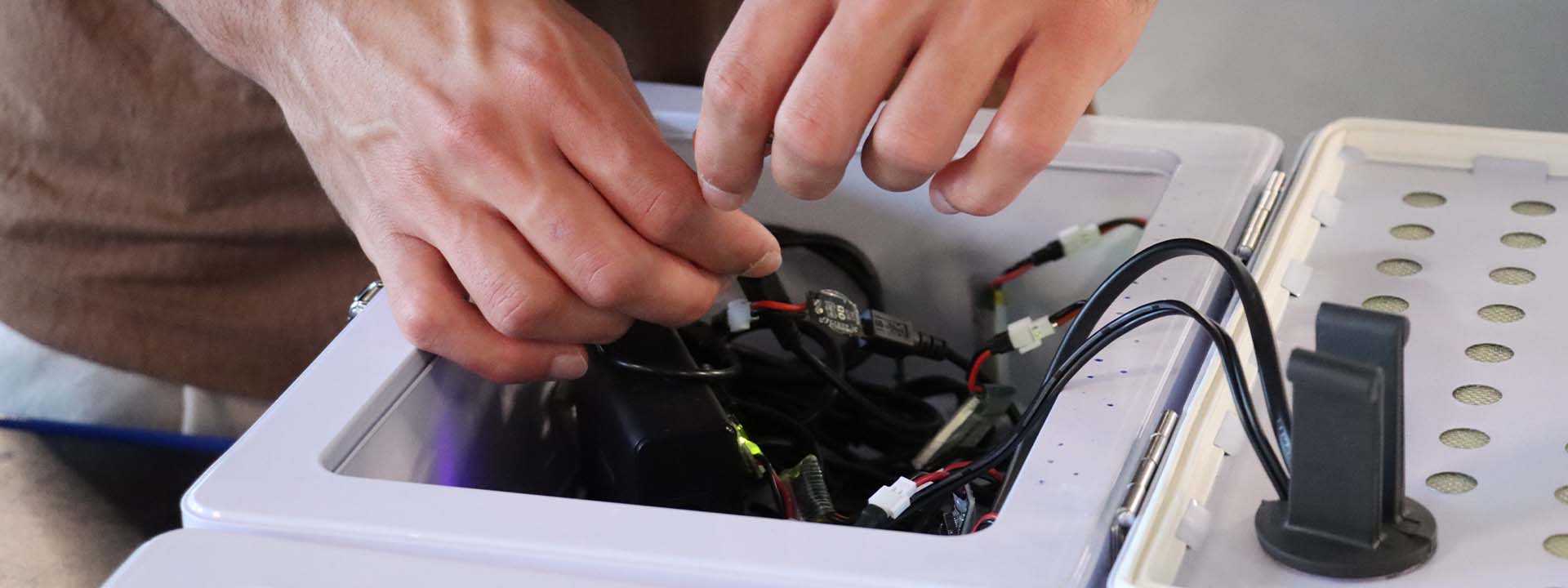
Bitcraze invests heavily in maintaining firmware, documentation, development tools and community support. Those efforts are funded by selling hardware that researchers and developers trust.
The company also has responsibilities that go beyond publishing code. Safety matters when products can fly. Quality matters when researchers need consistent, reproducible hardware. Trademarks matter because users should know they’re buying genuine Bitcraze products and receiving the level of support they expect.
Drawing boundaries doesn’t contradict openness. It’s part of making openness sustainable.
A philosophy that has aged well
Open source was already a major force when the first Crazyflie was built. The practical truth is that openness was the right fit for the kind of platform we wanted to build. The Crazyflie was never meant to be a sealed product. It was meant to be explored, modified and built upon. That made openness a natural engineering choice.
Over time, that choice has aged well. Researchers increasingly care about platforms they can inspect and reproduce. Students need systems they can learn from, not only operate. Developers want tools they can extend instead of work around.
Those are exactly the kinds of people Crazyflie was built for.
More than a licensing model
Openness is partly defined by license terms, but its practical value is measured by what it allows people to do. A useful development platform should help people explore ideas, understand how things work and build something new on top of what already exists.
That was the motivation behind the first Crazyflie, and it is still the principle that guides Bitcraze today.
If you’re interested in the details of how Bitcraze approaches licensing, hardware and software openness, we’ve collected those principles on our Open Source Philosophy page.