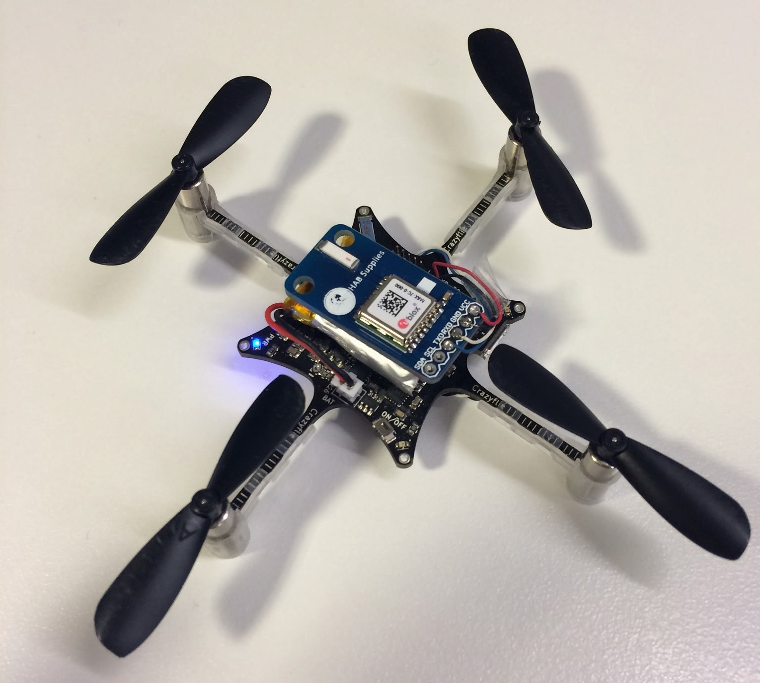
A couple of weeks ago we attached a uBlox MAX-7 GPS module to the Crazyflie (blog post). Back then it was mostly a proof of concept, all we did was to re-route the raw GPS data (in text NMEA format) directly to the PC using the Crazyflie text console port. This allowed us to quickly prove that a GPS can work on the Crazyflie but was not that useful and efficient: the copter did not decode the gps position and a lot of radio bandwidth was used. Last Friday we decided to fix it and to make it clean(er).
The ultimate goal was to measure the Crazyflie speed, if it wasn’t for the rain we could have done the measurement! Anyway, this work allowed us to exercise the debug functionality of the Crazyflie platform and so to see the strength of it but also what needs to be enhanced. In this post we will try to document (at high level) the steps taken to implement the GPS in the Crazyflie. The source code is pushed in the crazyflie firmware and python-client git repos. The Python client code is in the master branch and the firmware code in the gpu_ublox_dev branch (dev branch means that the code is far from final/clean, but it works!).
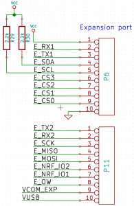
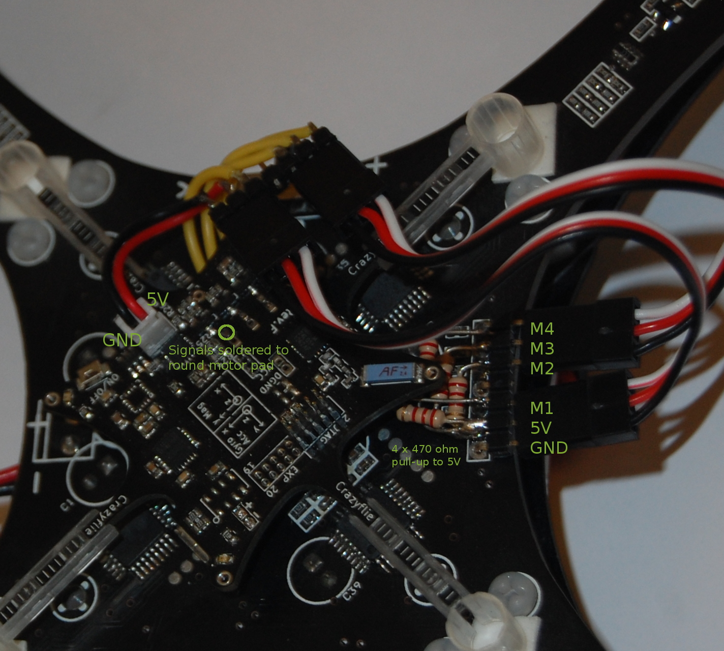
Electronically the GPS is connected using only 4 pins: VCC, GND, serial RX and serial TX. The serial port is connected to pins 3 and 5 of the expansion header. The power is connected to VCC.

The electronic was already tested and working so we had 2 tasks left:
- Decoding the GPS information in the firmware and creating log variables to make the data available for the PC software
- Updating the GPS tab of the PC software to fetch GPS data from the log subsystem instead of parsing it from the text console
It happens that these two tasks could be done mostly independently and Marcus and I started to work in parallel. The only thing we had to agree upon was which log variable and what scaling to use for the variables. We used the format that the GPS chip is already using which made things easier.
Firmware
For the firmware part, the first step was to acquire the GPS data. GPS chips usually can talk two languages: the standard text-based NMEA and some kind of proprietary binary format, UBX for uBlox. I chose the binary format as it is a lot easier use in C: no text parsing has to be done, all data dirrectly fits in a C structure. But first the GPS has to be setup to output data in binary modes and to output the data we were interested in. To quickly setup the GPS I used a tool that uBlox provides and that permits to generate proper UBX messages:
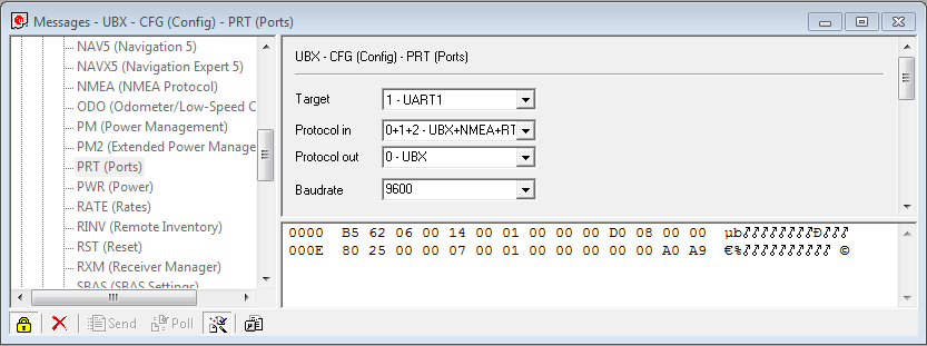
Two UBX messages where required: One to disable NMEA output and one to enable the NAV-PVP message which contains basically all data you would want from a GPS (position, speed, date and the accuracy). Once this is sent to the GPS chip it starts to send a NAV-PVP UBX packet once a second. Then, the GPS acquisition loop in the Crazyflie (currently implemented in the UART task, so it has to be moved into a proper driver) just has to wait for an UBX packet, read it and if it is a NAV-PVT packet then extract values from it. The GPX code has been tested on PC using another uBlox receiver connected to a USB serial cable. Then after copying the newly added uartReceiveUbx() function into the Crazyflie firmware, the GPS acquisition loop looks like this:
  while(1)
  {
    uartReceiveUbx(&msg, 100);

    if (msg.class_id == NAV_PVT) {
      gps_fixType = msg.nav_pvt->fixType;
      gps_lat = msg.nav_pvt->lat;
      gps_lon = msg.nav_pvt->lon;
      gps_hMSL = msg.nav_pvt->hMSL;
      gps_hAcc = msg.nav_pvt->hAcc;
      gps_gSpeed = msg.nav_pvt->gSpeed;
      gps_heading = msg.nav_pvt->heading;
    }

    ledseqRun(LED_GREEN, seq_linkup);
  }
The last thing, to make the data available from the PC, is to add a GPS log block and to add variables to it:
LOG_GROUP_START(gps)
LOG_ADD(LOG_UINT8, fixType, &gps_fixType)
LOG_ADD(LOG_INT32, lat, &gps_lat)
LOG_ADD(LOG_INT32, lon, &gps_lon)
LOG_ADD(LOG_INT32, hMSL, &gps_hMSL)
LOG_ADD(LOG_UINT32, hAcc, &gps_hAcc)
LOG_ADD(LOG_INT32, gSpeed, &gps_gSpeed)
LOG_ADD(LOG_INT32, heading, &gps_heading)
LOG_GROUP_STOP(gps)
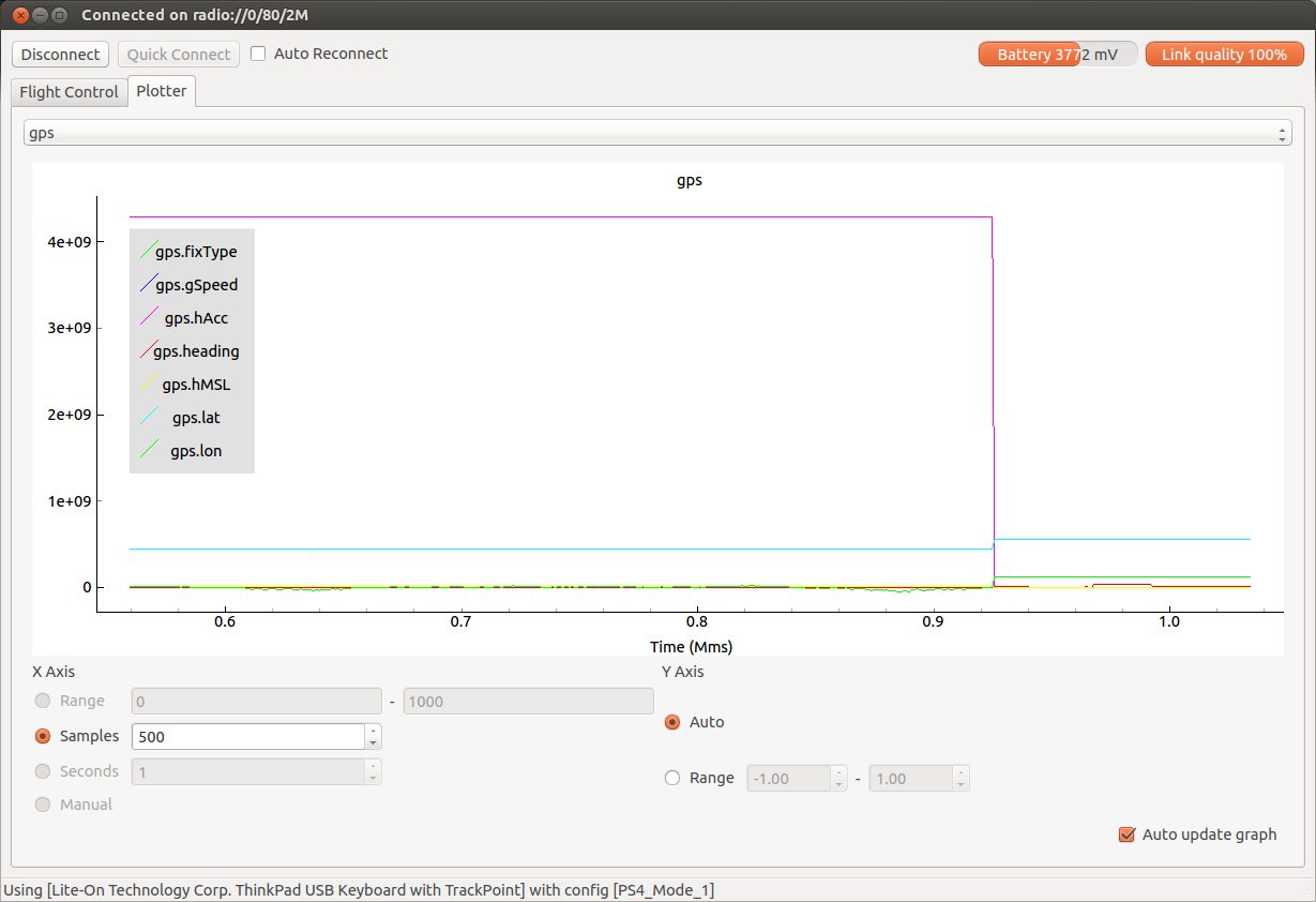
Debugging the firmware code can be done using the client log plotter tab, not so nice to look at positioning but good enough to see if it is working (when the accuracy, gps.hAcc, goes down the GPS has a fix!):

Client
Once the log block was decided, Marcus could start the client development by updating the debug driver. The debug link is a module of the Python client that behaves like a CRTP (the Crazyflie protocol) link but is in fact just some software running offline. It allows to easily develop and debug the client without requiring the usage of a Crazyflie. The debug link was modified to include all variable that the Crazyflie would eventually contain and to give them some value that can be logged.
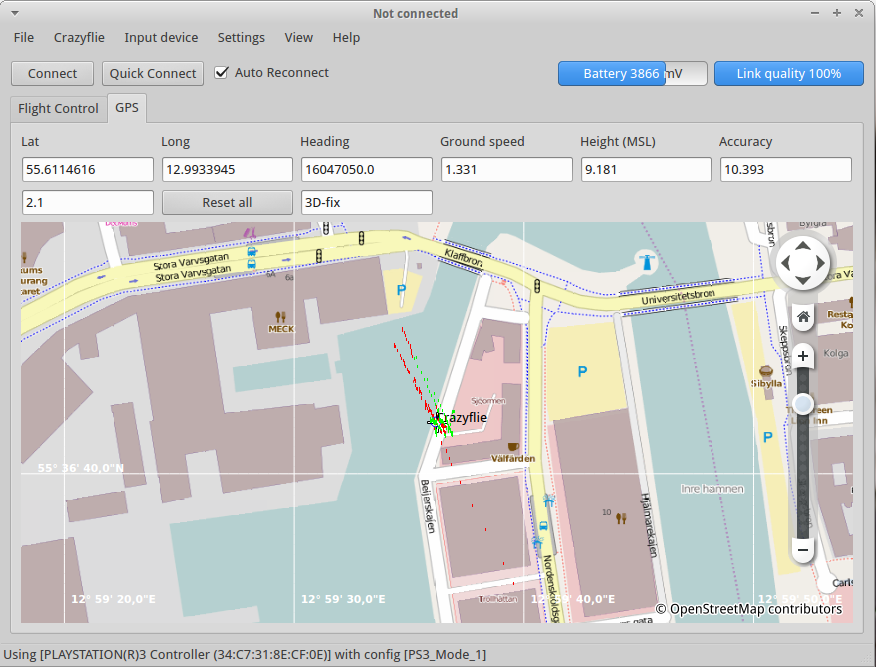
When this was done, the GPS tab has to be updated to display actual values, a max speed and reset button is also added (the idea was to measure the Crazyflie speed). After fighting more than expected with the QT layouts the result is good enough:
Note that the client uses the Python binding of KDE Marble which has to be compiled manually. Only Marcus has had the courage to do that on his computer, but luckily he also compiled it on the latest Bitcraze VM so that we can all easily enjoy the new GPS tab :).
Merge
Now that the client and the firmware are made separately we ‘just’ have to connect the new client to the new firmware. And guess what? it worked the first time :-) (Yes I know you have no reason to believe me but this time it really worked the first time).
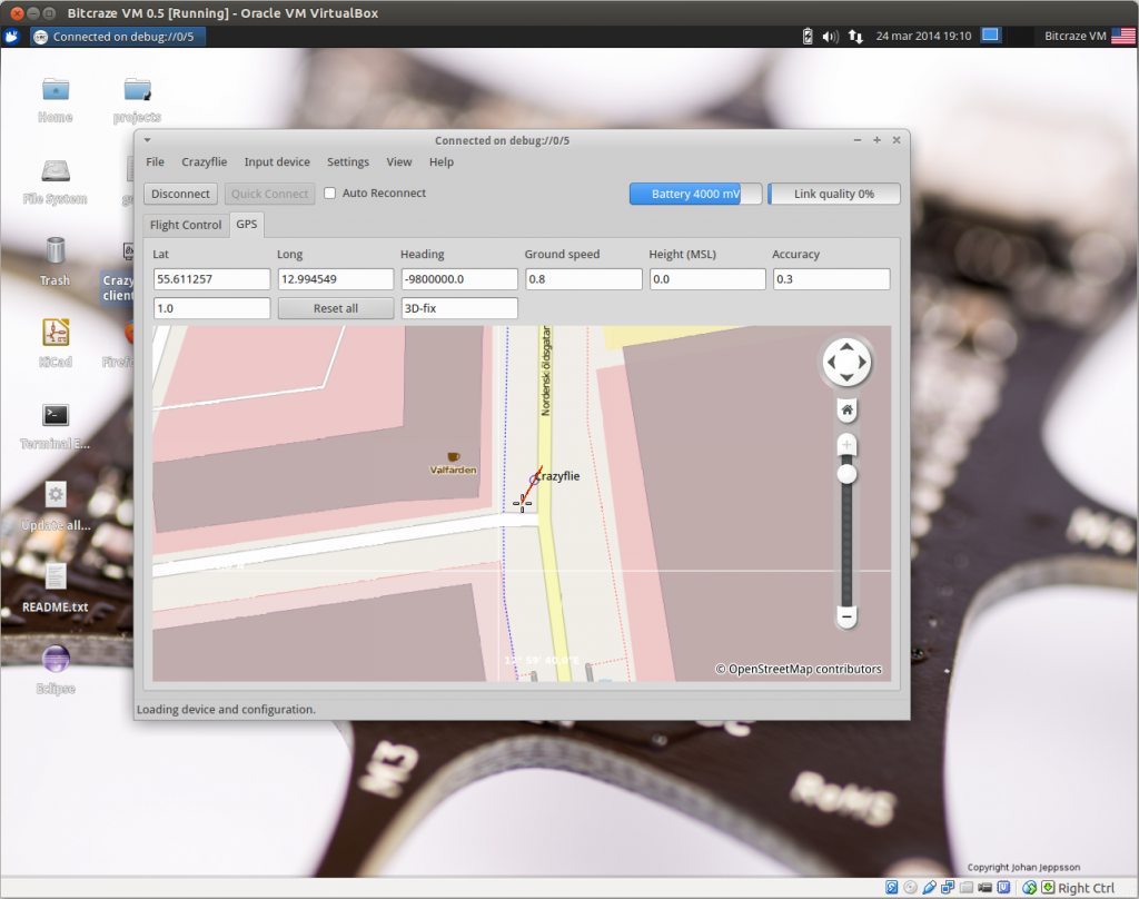
Unfortunately for us last Friday was one of these Swedish rainy day, all we could do was to take turns to stand in the middle of the road outside of our office, in the rain, holding the Crazyflie in a plastic bag and waiting for the GPS to get a fix (people passing by were looking quite strangely at us …). It happens that the rain where not helping at all! And the fact that we don’t have assisted-GPS (yet) means that the GPS would get a fix in 40sec best case, it took about 5-10minutes for us. But eventually we got the fix:
Conclusion
One thing we have to work on is the modularity of the firmware. Things like having a clear and easy to use HAL for peripherals on the extension port. It is on our ToDo list and it would have been useful here to do a cleaner job with the firmware implementation. A good thing is that while this implementation is uBlox specific for the firmware part, it is completely hardware-independent on the client side. It means that it is possible to implement any kind of positioning, with other GPS chip or other technology, and as long as this positioning declares the right log variable the client will work with it unmodified.
As for the GPS, uploading assistance data to the Crazyflie would permit to drastically reduce the fix time to about 10-15sec. Also this GPS is capable of 10Hz update rate which would be nice to test. The GPS on a Crazyflie is still mostly a proof-of-concept and is of course not useful for indoor flight. Though with light winds the Crazyflie is pretty capable outdoor, so with GPS capability it could be interesting to experiment a bit with trajectory planing. Of course this is even more true for country with a warm and dry weather :-).