The Crazyflie 2.0 has been flyable in MoCap systems such as Qualisys, Vicon or Optitrack for quite a while thanks to the Crazyswarm project. For the MoCap systems to be able to track the Crazyflie it needs to be fitted with reflective markers. These can be attached on e.g the motor mounts which in some cases might be the best solution, however we also liked the idea of creating a deck where the markers easily can be attached and in many, repeatable configurations, that is why we created the Mocap deck. This deck is now soon to be released but before we start manufacturing it would be great to get some feedback.
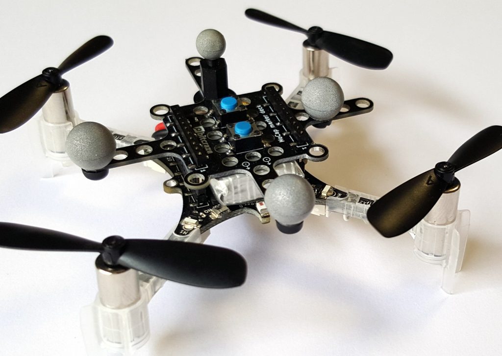
The deck has M3 sized holes which is spaced on a 5mm grid. The deck also has footprints for two optional push buttons that can be used to e.g. trigger a take-off or start of a demo. And as the battery holder deck, which has no electronics, so this can be mounted upside down for better fitting of the markers, if the buttons aren’t mounted of course.
We are collaborating with Qualisys, also based in Sweden (in Gothenburg), to make the Crazyflie more moCap friendly and make it easy to use together with the Qualisys system as well as other mocap systems. Qualisys will provide the markers for the moCap deck.
Qualisys and Bitcraze are exhibiting together at IROS in Madrid where we will show some awesome demos with a moCap system as well as other position technologies and we are also hoping to fly a Crazyswarm. We will publish more information when we get closer to the conference.
Here at the USC ACT Lab we conduct research on coordinated multi-robot systems. One topic we are particularly interested in is coordinating teams consisting of multiple types of robots with different physical capabilities.
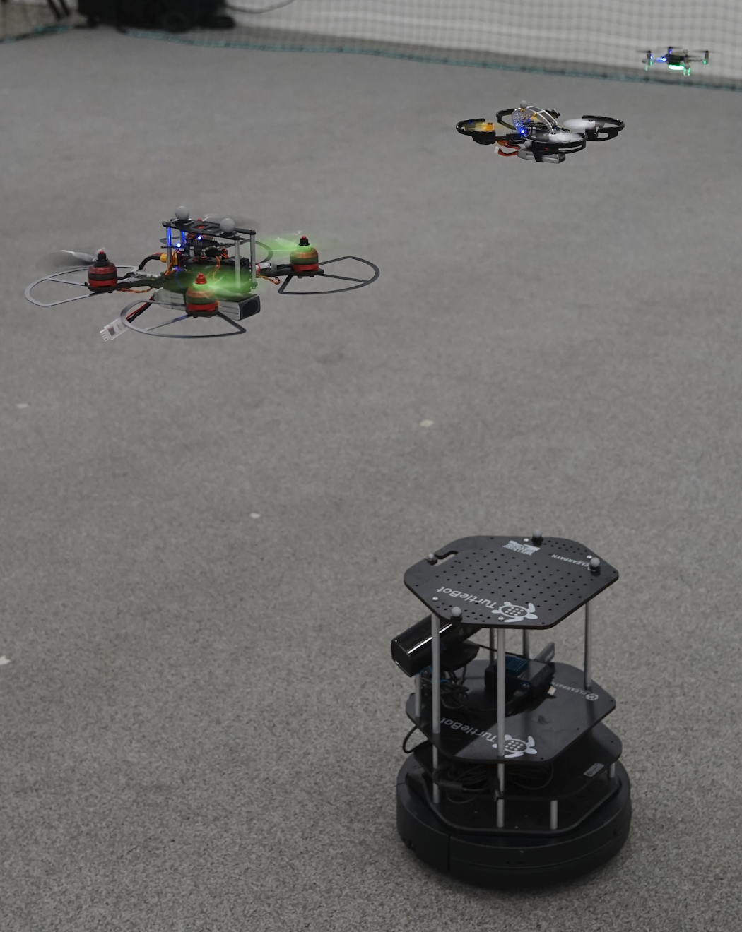
A team of three quadrotors all controlled with Crazyflie 2.0 and a Clearpath Turtlebot
Applications such as search and rescue or mapping could benefit from such heterogeneous teams because they allow for more flexibility in the choice of sensors and locomotive capability. A core challenge for any multi-robot application is motion planning – all of the robots in the team need to make it to their target locations efficiently while avoiding collisions with each other and the environment. We have recently demonstrated a scalable method for trajectory planning for heterogeneous robot teams utilizing the Crazyflie 2.0 as the flight controller for our aerial robots.
A Crazier Swarm
To test our trajectory planning research we wanted to assemble a team with both ground robots and multiple sizes of aerial robots. We additionally wanted to leverage our existing Crazyswarm software and experience with Crazyflie firmware to avoid some of the challenges of working with new hardware. Luckily for us the BigQuad deck offered a straightforward way to super-size the Crazyflie 2.0 and gave us the utility we needed.
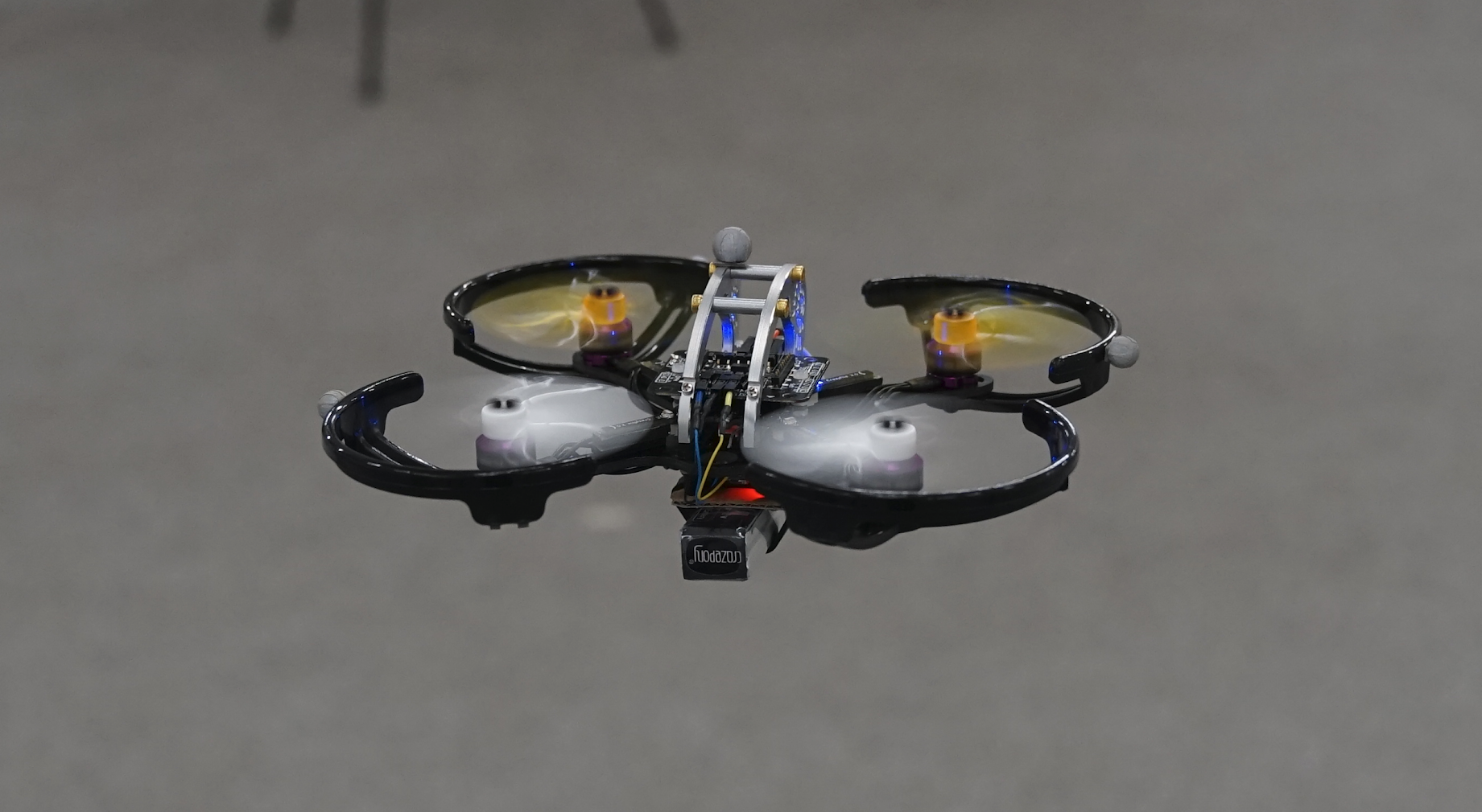
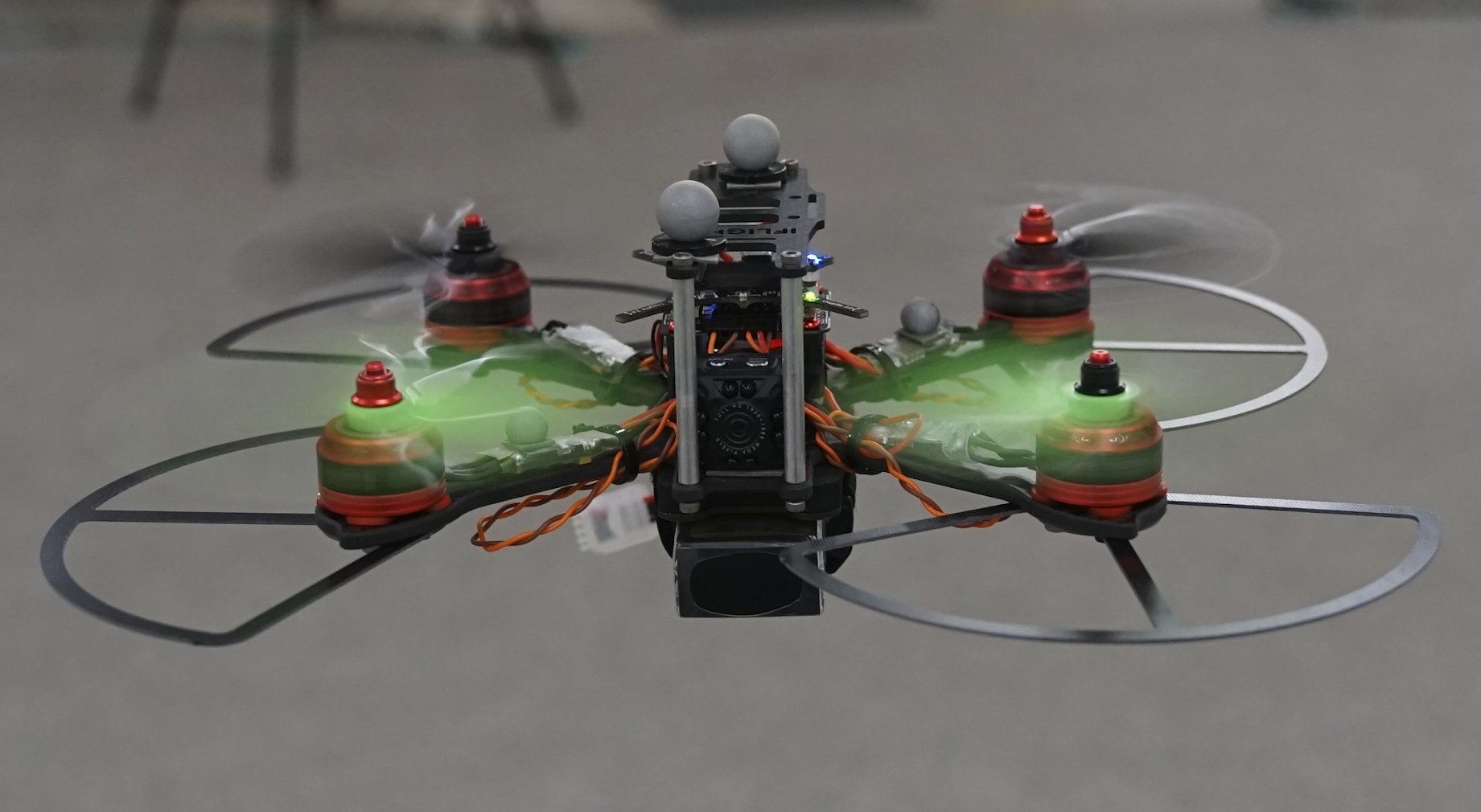
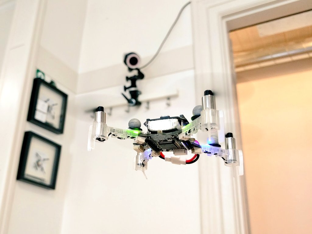
With the BigQuad deck and off-the-shelf components from the hobbyist drone community we built three super-sized Crazyflie 2.0s. Two of them weigh 120g (incl. battery) with a motor-to-motor size of 130mm, and the other is 490g (incl. battery and camera) with a size of 210mm.
120g, 130mm
490g, 210mm
We wanted to pick components that would be resistant to crashing while still offering high performance. To meet these requirements we ended up picking components inspired by the FPV drone racing community where both reliable performance and high-impact crashes are expected. Full parts lists for both platforms are available here
Integrating the new platforms into the Crazyswarm was fairly easy. We first had to re-tune the PID controller gains to account for the different dynamics of the larger platforms. This didn’t take too long, but we did crash a few times — luckily the components we chose were able to handle the crashes without any breakages. After tuning the platforms behave very well and are just as easy to work with as the original Crazyflie 2.0. We additionally updated the Crazyswarm package to be able to differentiate between BigQuad and regular Crazyflie types and those updates are now available for use by anyone!
In future work, we are excited to do hands-on experiments with a prototype of the CF-RZR. This new board seems like a promising upgrade to the CF 2.0 + BQD combination as it has upgraded components, an external antenna, and a standardized form factor. Hopefully we will see the CF-RZR as part of the Crazyswarm in the near future!
During the fall we did two blog-posts (1, 2) about a new prototype named Obstacle Avoidance/SLAM deck, but since then it’s been a bit quiet about it. So we thought it was due for an update! First of all, after a lot of discussions, we decided to rename the deck to Multi-ranger. It better describes what the board does and matches the naming of the Z-ranger. We’ve sent out some samples to customers and so far the response has been great. So we’re pushing forward and preparing for production that’s estimated to begin in March. Below is a picture of the latest prototype.
The biggest change for the final prototype is adding a LDO regulator to power the sensors. We’ve seen that depending on the settings for the sensors they might consume a lot more than when we initially tested. Using the same settings as for the Z-ranger brings the consumption to 90 mA, which together with the Crazyflie 2.0 electronics, comes close to filling the power budget for the Crazyflie 2.0 VCC LDO regulator. Aside from that we’re making some minor changes to simplify production and testing.
We have been lucky get the opportunity to use a motion capture system from Qualisys in our flight lab. The Qualisys system is a camera based system that is using IR-cameras to track objects with sub-millimeter precision! The cameras are designed to measure the position and track small reflective marker balls that are fixed to the object to be tracked with high accuracy. By using multiple cameras shooting from different angles it is possible for the system to calculate the 3D position of a marker in space. By mounting multiple markers on an object the system can also identify the object as well as its orientation in space. Very cool!
We have started to look at how to add support in our ecosystem for the Qualisys system as well as other “external” positioning systems, external in this context is systems that calculate the position outside the Crazyflie. There is already great support for external positioning in the CrazySwarm project by the USC-ACTLab, but we are now looking at light weight support in the python client. We are not sure what we will add but ideas are on the lines of viewing an external position in the client, feed an external position into the Crazyflie for autonomous flight and maybe a simple trajectory sequencer.
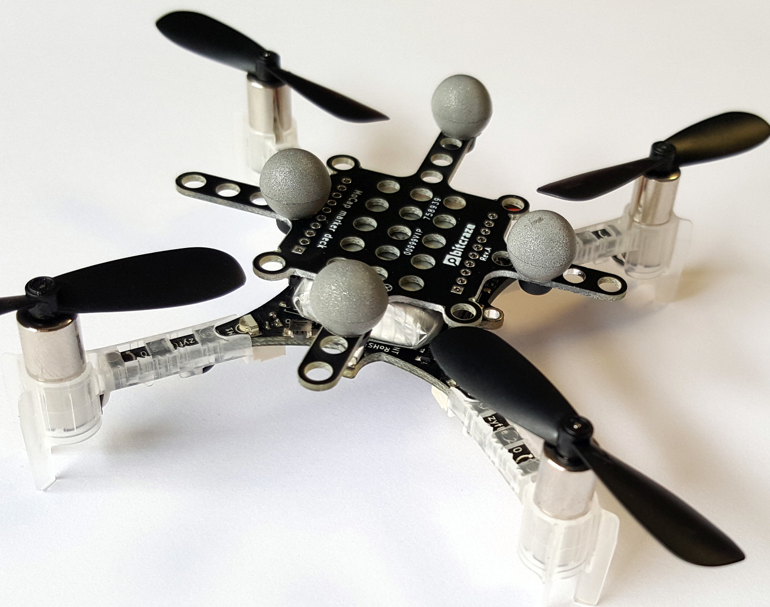
MoCap Deck
We have also started to design a MoCap Deck to make it easy to mount reflective markers on the Crazyflie. Our design goals include:
* light weight
* easy to use
* support for multiple configurations to enable identification of individuals
* the possibility to add a button for human interaction
The suggested design of the MoCap Deck
Any feedback on the MoCap Deck and ideas for functionality to add to the client is welcome! Please add a comment to this blog post or send us an email.
We will write more about the Qualisys system later on, stay tuned!
Modular robots can adapt and offer solutions in emergency scenarios, but self-assembling on the ground is a slow process. What about self-assembling in midair?
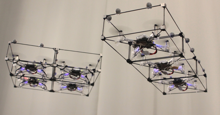
In one of our recent work in GRASP Laboratory at University of Pennsylvania, we introduce ModQuad, a novel flying modular robotic structure that is able to self-assemble in midair and cooperatively fly. This work is directed by Professor Vijay Kumar and Professor Mark Yim. We are focused on developing bio-inspired techniques for Flying Modular Robots. Our main interest is to develop algorithms and controllers for self-assembling modular robots that can dock in midair.
In biological systems such as ant or bee colonies, collective effort can solve problems not efficient with individuals such as exploring, transporting food and building massive structures. Some ant species are able to build living bridges by clinging to one another and span the gaps in the foraging trail. This capability allows them to rapidly connect disjoint areas in order to transport food and resources to their colonies. Recent works in robotics have been focusing on using swarm behaviors to solve collective tasks such as construction and transportation.Docking modules in midair offers an advantage in terms of speed during the assembly process. For example, in a building on fire, the individual modules can rapidly navigate from a base-station to the target through cluttered environments. Then, they can assemble bridges or platforms near windows in the building to offer alternative exits to save lives.
ModQuad Design
The ModQuad is propelled by a quadrotor platform. We use the Crazyflie 2.0. The vehicle was chosen because of its agility and scalability. The low-cost and total payload gives us an acceptable scenario for a large number of modules.
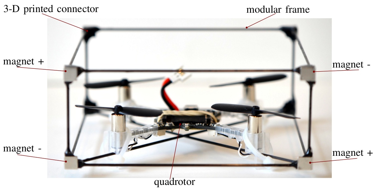
Very light-weight carbon fiber rods connected by eight 3-D printed ABS connectors form the frame. The frame weight is important due to tight payload constraints of the quadrotor. Our current frame design weighs 7g about half the payload capability. The module geometry has a cuboid shape as seen in the figure below. To enable rigid attachments between modules, we include a docking mechanism in the modular frame. In our case, we used Neodymium Iron Boron (NdFeB) magnets as passive actuators.
Self-Assembling and Cooperative Flying
ModQuad is the first modular system that is able to self-assemble in midair. We developed a docking method that accurately aligns and attaches pairs of flying structures in midair. We also designed a stable decentralized modular attitude controller to allow a set of attached modules to cooperatively fly. Our controller maximizes the use of the rotor forces by generating the maximum possible moment.
In order to allow the flying structure to navigate in a three dimensional environment, we control thrust and attitude to generate vertical and horizontal translations, and rotation in the yaw angle. In our approach, we control the attitude of the structure in a decentralized manner. A modular attitude controller allows multiple connected robots to stably and cooperatively fly. The gain constants in our controller do not need to be re-tuned as the configurations change.
In order to dock pairs of flying structures in midair, we propose to have two flying structures: the first one is hovering and waiting, meanwhile the second one is performing a docking action. Both, the hovering and the docking actions are based on a velocity controller. Using a velocity controller, we are able to dock multiple robots in midair. We highlight that docking robots in midair is one of the fastest ways to assemble structures because the building units can rapidly move and dock in three dimensional environments. The docking system and control has been validated through multiple experiments.
Our system takes advantage of robot swarms because a large number of robots can construct massive structures.
This work was developed by:
David Saldaña, Bruno Gabrich, Guanrui Li, Mak Yim, and Vijay Kumar.
Grasping objects is a hard task that usually implies a dedicated mechanism (e.g arm, gripper) to the robot. Instead of adding extra components, have you thought about embedding the grasping capability to the robot itself? Have you also thought about whether we could do it flying?
In the GRASP Laboratory at the University of Pennsylvania, we are concerned about controlling robots to perform useful tasks. In this work, we present the Flying Gripper! It is a novel flying modular platform capable of grasping and transporting objects with the help of multiple quadrotors (crazyflies) working together. This research project is coordinated by Professor Mark Yim and Professor Vijay Kumar, and led by Bruno Gabrich (PhD candidate) and David Saldaña (Postdoctoral researcher).
Inspiration in Nature
In nature, cooperative work allows small insects to manipulate and transport objects often heavier than the individuals. Unlike the collaboration in the ground, collaboration in air is more complex especially considering flight stability. With this inspiration, we developed a platform composed of four cooperative identical modules where each is based on a quadrotor (crazyflies) within a cuboid frame with a docking mechanism. Pair of modules are able to fly independently and physically connect by matching their vertical edges forming a hinge. Four one degree of freedom (DOF) connections results in a one DOF four-bar linkage that can be used to grasp external objects. With this platform we are able to change the shape of the flying vehicle during flight and use its own body to constrain and grasp an object.
Flying Gripper Design and Motion
In the proposed modular platform, we use the Crazyflie 2.0. Its battery life lasts around seven minutes, though in our case battery life time is reduced due to the extra weight. The motor mounting was modified from the standard design, we tilted the rotors 15 degrees. This was necessary as more yaw authority was required to enable grasping as a four-bar. However, adding this tilt reduces the lifting thrust by 3%. Axially aligned cylindrical Neodymium Iron Boron (Nd-FeB) magnets, with 1/8″ of diameter and 1/4″ of thickness are mounted on each corner enabling edge-to-edge connections. The cylindrical magnets have mass of 0.377g and are able to generate a force of 0.4 kg in a tangential connection between two of the same magnets. This forms a strong bond when two modules connect in flight. Note that the connections are not rigid – each forms a one DOF hinge.
The four attached modules results in a one DOF four bar linkage in addition to the combined position and attitude of the conglomerate. The four-bar internal angles are controlled by controlling the yaw attitude of each module. For example, two modules rotate clockwise and other two modules rotate counter-clockwise in a coordinated manner.
Grasping Objects
Collaborative manipulation in air is an alternative to reduce the complexity of adding manipulator arms to flying vehicles. In the following video we are able to see the Flying Gripper changing its shape in midair to accomplish the complex task of grasping a wished coffee cup. Would you like some coffee delivery?
This work was developed by:
Bruno Gabrich, David Saldaña, Vijay Kumar and Mark Yim
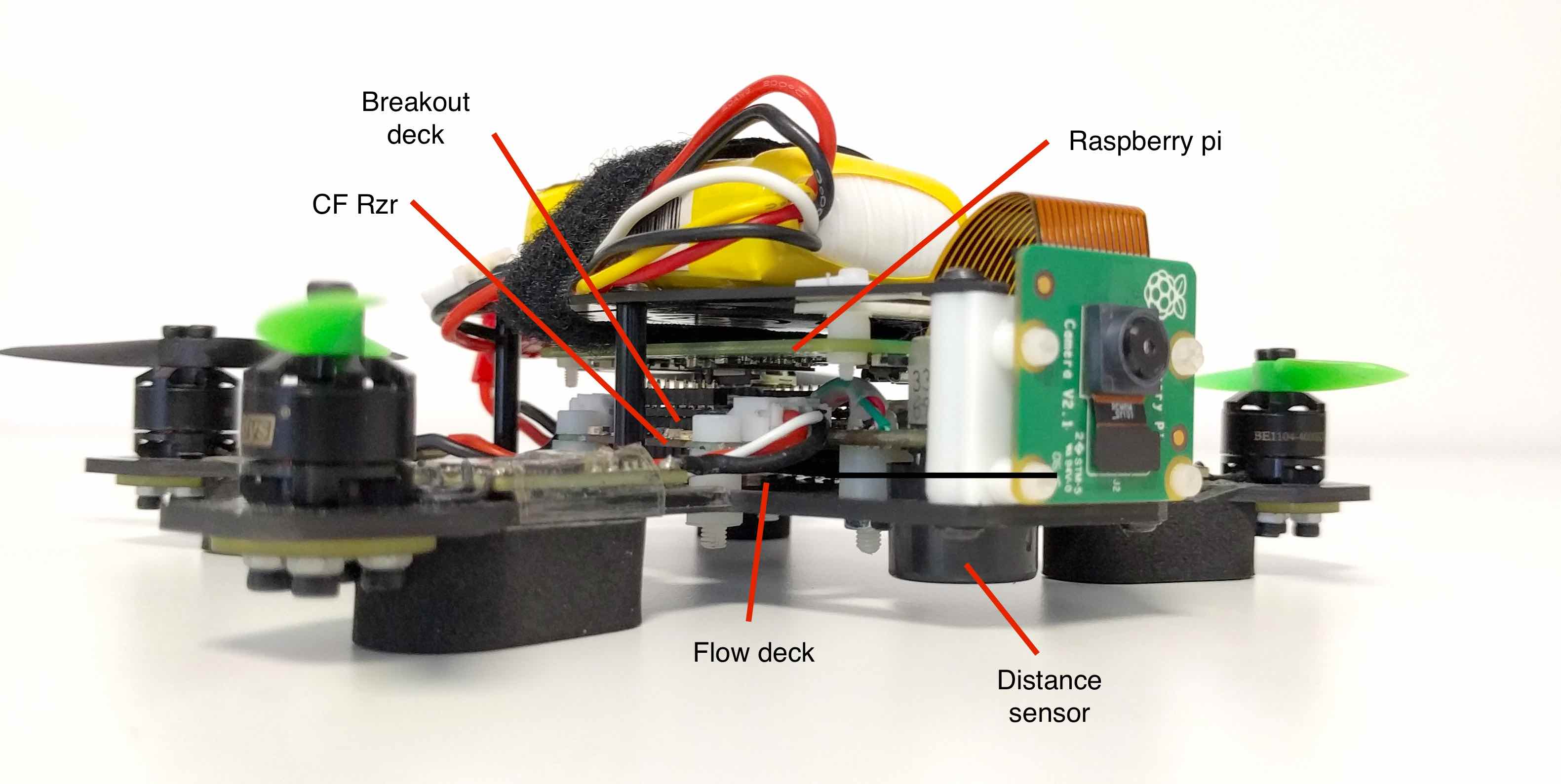
There have been a few requests from the community for a brushless Crazyflie and we blogged about a prototype we are working on a few weeks ago. The most common reason for wanting brushless motors is to be able to carry more load, in most cases a camera. A camera could be used for FPV flying or open up various image processing use cases like understanding the would around the drone using SLAM. Image processing on-board requires quite a lot of processing power and the CPU in the Crazyflie could not handle that, so more processing power would be required for a scenario like that. It is summer time (with a slight touch of play time) so we wanted to see what we could do with the CF Rzr and if it would be a useful platform for these types of applications. We hope that we might get some insights on the way as well.
We set the goal to try to add a camera, a small “computer”, the Flow deck for assisted flying, FPV capabilities and support for a standard RC controller.
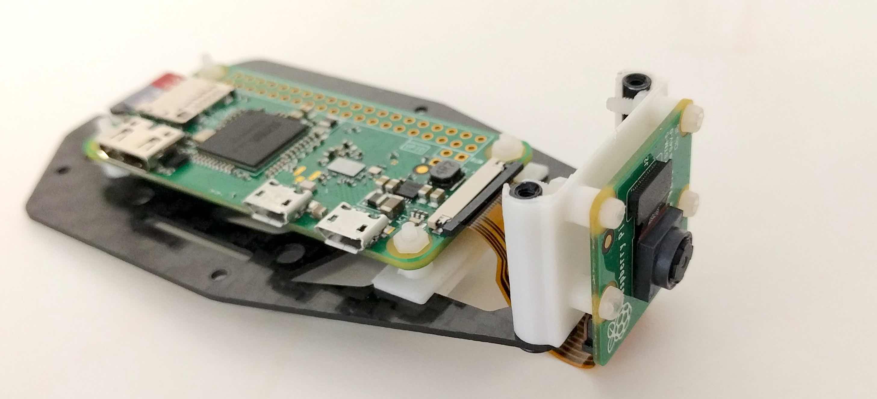
We chose the Raspberry pi zero-w in order to get video processing and video streaming from the quad as well as more computing power. The Raspberry pi zero is not the most powerful board our there but it has a couple of advantage for our prototype:
It has a readily available, good quality camera and good software support for it
It has an analog video output and hardware streaming support, which means that the quad could be flown FPV using the Raspberry pi camera
It has hardware JPEG and H264 encoders that will enable us to save and stream images and videos if we want to
Raspberry pi and camera mounted on the top part of the frame
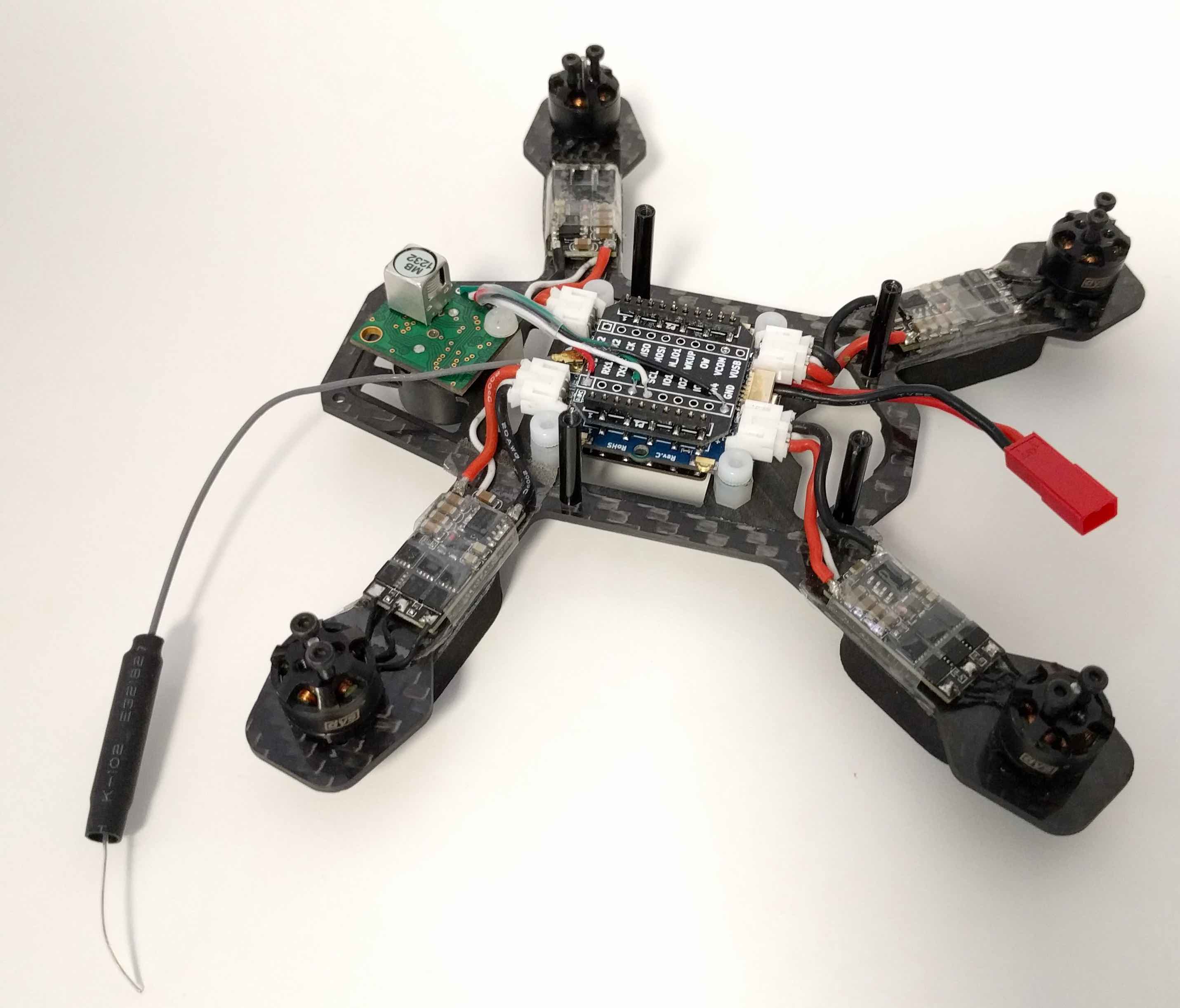
For assisted flight and improved stability, the XY-part of the Flow deck works fine outdoors but the laser height sensor on the deck has a maximum limit of 1-2 meters, and further more it does not go well with direct sunlight. We decided to add an ultrasound sonar distance sensor to measure the height instead. The ultrasound sonar connects via I2C and was simply soldered to a breakout deck that plugs into the CF Rzr.
Crazyflie Rzr with ultrasonic sonar, breakout deck and flow deck mounted on the lower part of the frame
The first step is to see if we can physically fit everything on the frame. With some 3D printed mounts for the camera and the Raspberry pi, we think it starts to look pretty good. Next step will be to squeeze in the FPV video transmitter board, the RC receiver board and finally connect everything together.
The current setup with everything mounted
We are far from done but it is a good start, and it is fun.
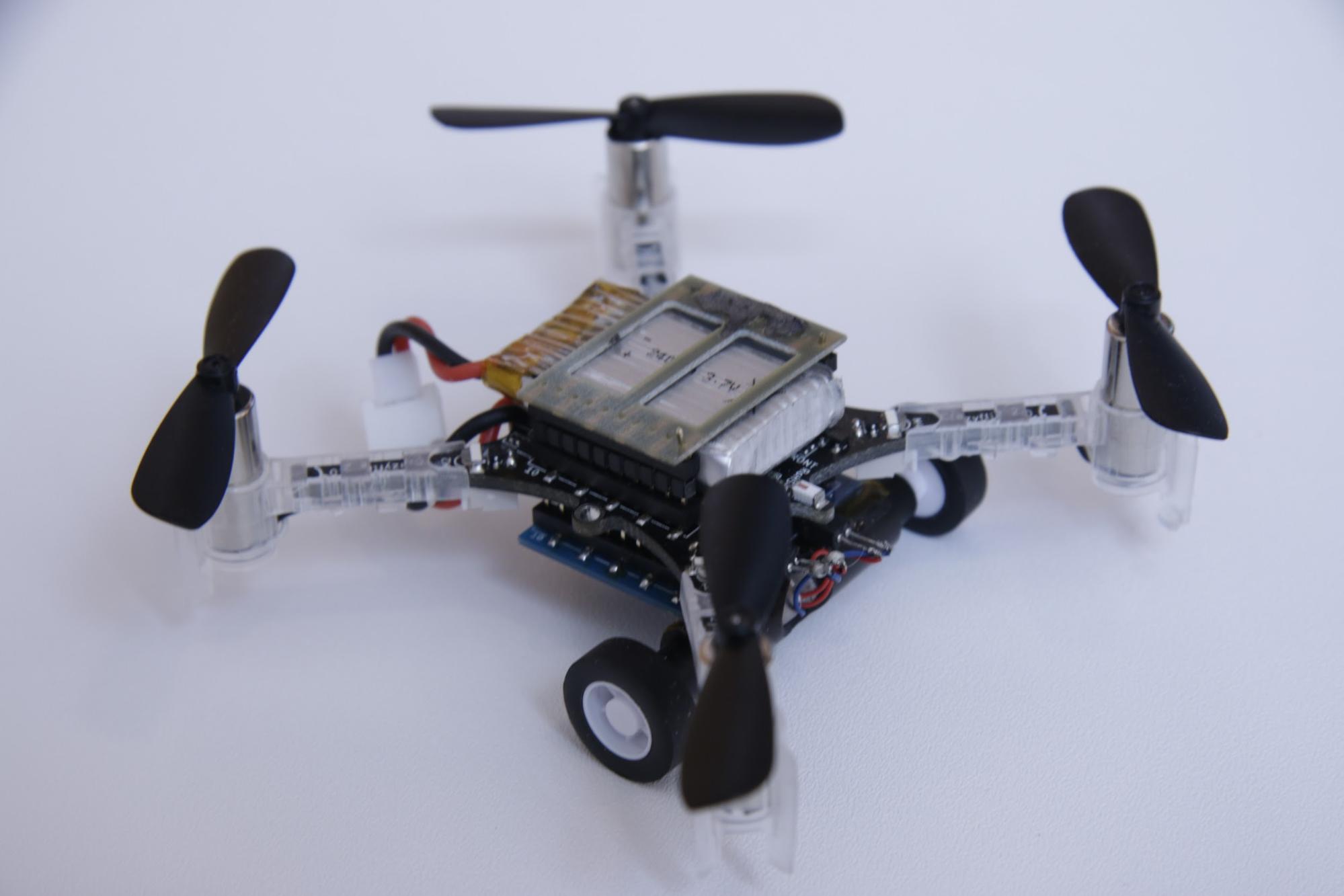
Robots that can both fly and drive – in particular wheeled drones – are actually somewhat of a rarity in robotics research. Although there are several interesting examples in the literature, most of them involve creative ways of repurposing the wings or propellers of a flying robot to get it to move on the ground. Since we wanted to test multi-robot algorithms, we needed a robot that would be robust, safe, and easy to control – not necessarily advanced or clever. We decided to put an independent driving mechanism on the bottom of a quadcopter, and it turns out that the Crazyflie 2.0 was the perfect platform for us. The Crazyflie is easily obtainable, safe, and (we can certify ourselves) very robust. Moreover, since it is open-source and fully programmable, we were able to easily modify the Crazyflie to fit our needs. Our final design with the wheel deck is shown below.
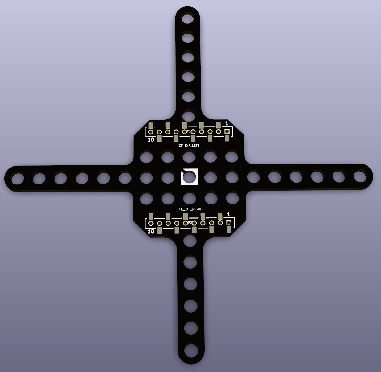
A photo of the Crazyflie 2.0 with the wheel deck.
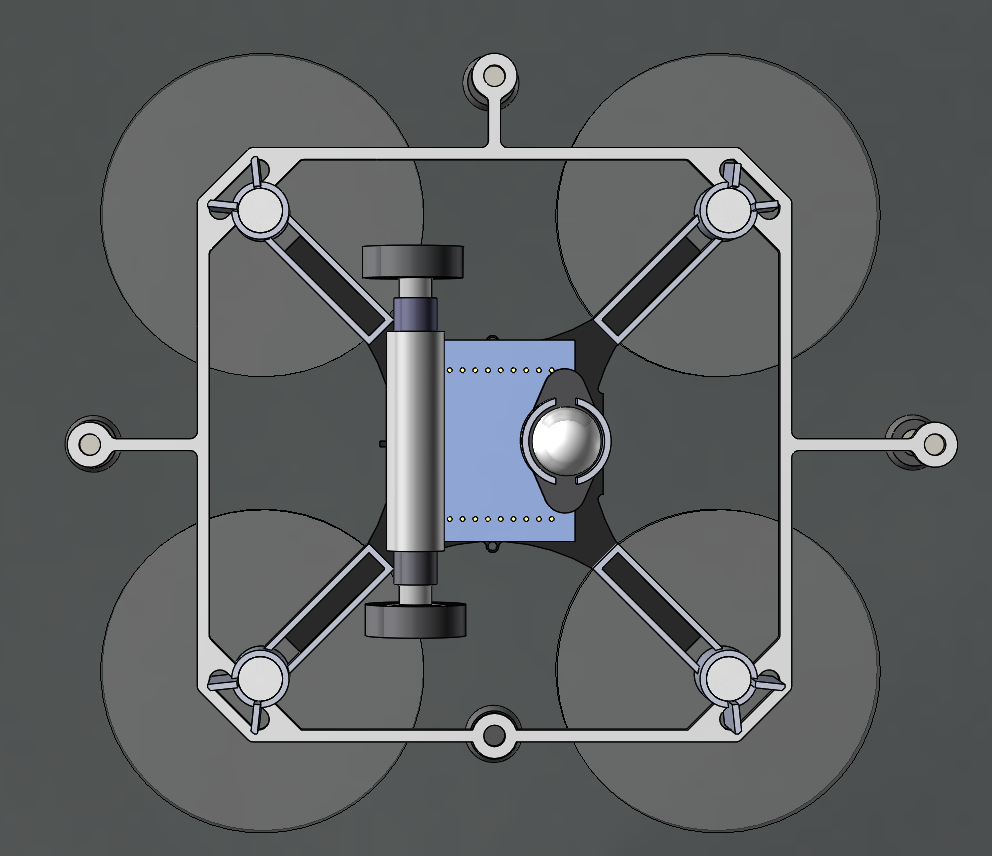
A model of the Crazyflie 2.0 with the wheel deck from the bottom
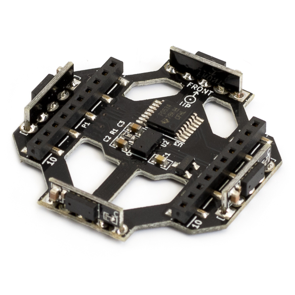
The wheel deck consists of a PCB with a motor driver; two small motors mounted in a carbon fiber tube epoxied onto the PCB; and a passive ball caster in the back. We were able to interface our PCB with the pins on the Crazyflie so that we could use the Crazyflie to control the motors (the code is available at https://github.com/braraki/crazyflie-firmware). We added new parameters to the Crazyflie to control wheel speed, which, in retrospect, was not a good decision, since we found that it was difficult to update the parameters at a high enough rate to control the wheels well. We should have used the Crazyflie RealTime Protocol (CRTP) to send custom data packages to the Crazyflie, but that will have to be a project for another day.
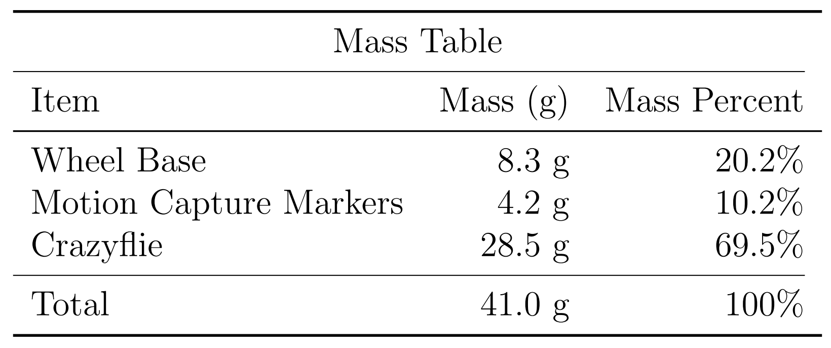
The table below shows the mass balance of our miniature ‘flying car.’ The wheels added 8.3g and the motion capture markers (we used a Vicon system to track the quads) added 4.2g. So overall the Crazyflie was able to carry 12.5g, or ~44% of its body weight, and still fly pretty well.
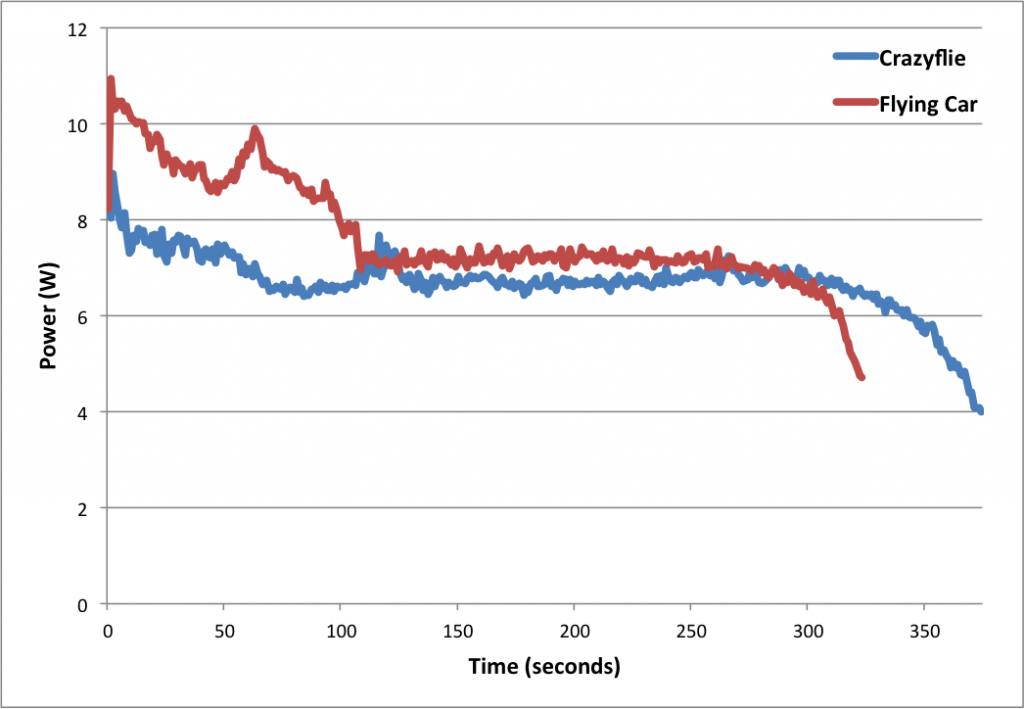
Next we measured the power consumption of the Crazyflie and the ‘Flying Car.’ As you can see in the graph below, the additional mass of the wheels reduced total flight time from 5.7 minutes to 5.0 minutes, a 42-second or 12.3% reduction.
Power consumption of the Crazyflie vs. the ‘Flying Car’
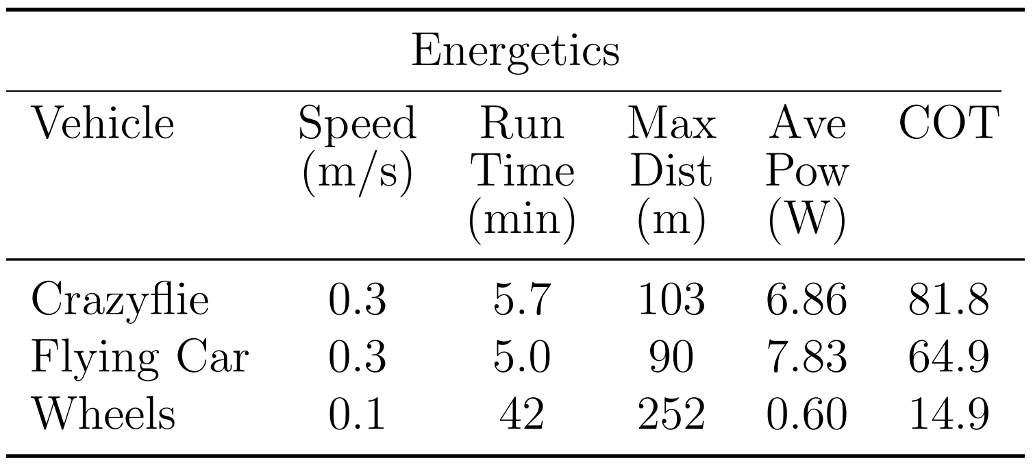
The table below shows more comparisons between flying without wheels, flying with wheels, and driving. The main takeaways are that driving is much more efficient than flying (in the case of quadcopter flight) and that adding wheels to the Crazyflie does not actually reduce flying performance very much (and in fact increases efficiency when measured using the ‘cost of transport’ metric, which factors in mass). These facts were very important for our planning algorithms, since the tradeoff between energy and speed is the main factor in deciding when to fly (fast but energy-inefficient) versus drive (slow but energy-efficient).
Controlling 8 Crazyflies at once was a challenge. The great work by the USC ACT Lab (J. A. Preiss, W. Hönig, G. S. Sukhatme, and N. Ayanian. “Crazyswarm: A Large Nano-Quadcopter Swarm,” ICRA 2017. https://github.com/USC-ACTLab/crazyswarm) has made our minor effort in this field obsolete, but I will describe our work briefly. We used the crazyflie_ros package, maintained by Wolfgang Hönig from the USC ACT Lab, to interface with the Crazyflies. Unfortunately, we found that a single Crazyradio could communicate with only 2 Crazyflies at a time using our methods, so we had to use 4 Crazyradios, and we had to make a ROS node that switched between the 4 radios rapidly to send commands. It was not ideal at all – moreover, we had to design 8 unique Vicon marker configurations, which was a challenge given the small size of the Crazyflies. In the end, we got our system to work, but the new Crazyswarm framework from the ACT Lab should enable much more impressive demos in the future (as has already been done in their ICRA paper and by the Robust Adaptive Systems Lab at Carnegie Mellon, which they described in their blog post here).
We used two controllers, an air and a ground controller. The ground controller was a simple pure pursuit controller that followed waypoints on ground paths. The differentially steered driving mechanism made ground control blissfully simple. The main challenge we faced was maximizing the rate at which we could send commands to the wheels via the parameter framework. For aerial control, we used simple PID controllers to make the quads follow waypoints. Although the wheel deck shifted the center of mass of the Crazyflie, giving it a tendency to slowly spin in midair, overall the system worked well given its simplicity.
Once we had the design and control of the flying cars figured out, we were able to test our path planning algorithms on them. You can see in the video below that our vehicles were able to faithfully follow the simulation and that they transitioned from flying to driving when necessary.
Our work had two goals. One was to show that multi-robot path planning algorithms can be adapted to work for vehicles that can both fly and drive to minimize energy consumption and time. The second goal was to showcase the utility of flying-and-driving vehicles. We were able to achieve these goals in our paper thanks in part to the ease of use and versatility of the Crazyflie 2.0.
A while ago I started working on a brushless motor control driver for the Crazyflie. I implemented most of it but did not really have time to test it. Recently we have gotten some request and questions about it so we took some time to do some further testing.
Implementing a brushless motor control driver can be done in many ways. If you have brushlesss motor controllers that can be controlled over I2C that could have been one way but usually the brushless motor controller (BLMC) take a PWM input. This is most commonly a square wave with a period of 20ms and a pulse width of 1-2 ms high, were 1 ms is 0%, and 2 ms is 100%. A period of 20 ms means a frequency of 50Hz. This is most often a high enough update rate for R/C electronics like servos etc. but when it comes to BLMC that is not the case. Therefore many new BLMC can read a much higher update rate of up to 400 Hz were the pulse still is 1-2 ms high. That way you can match the BLMC input to the update rate of the stabilization control loop and increase stability. In the code we added a define BLMC_PERIOD where this can be set.
To test this we wanted a frame which was quick to setup and found this. It is based of a PCB just like the Crazyflie and has the four motor controllers with it, perfect! The built in BLMC are based on an the Atmel MCU Atmega8 which is very commonly used in the R/C BLMC which means it is possible to re-flash them with the SimonK firmware. This is know to be a great firmware and enables fast PWM update rate etc. So we built and flashed the firmware configured for the tgy6a which is compatible and it worked right away, yay!
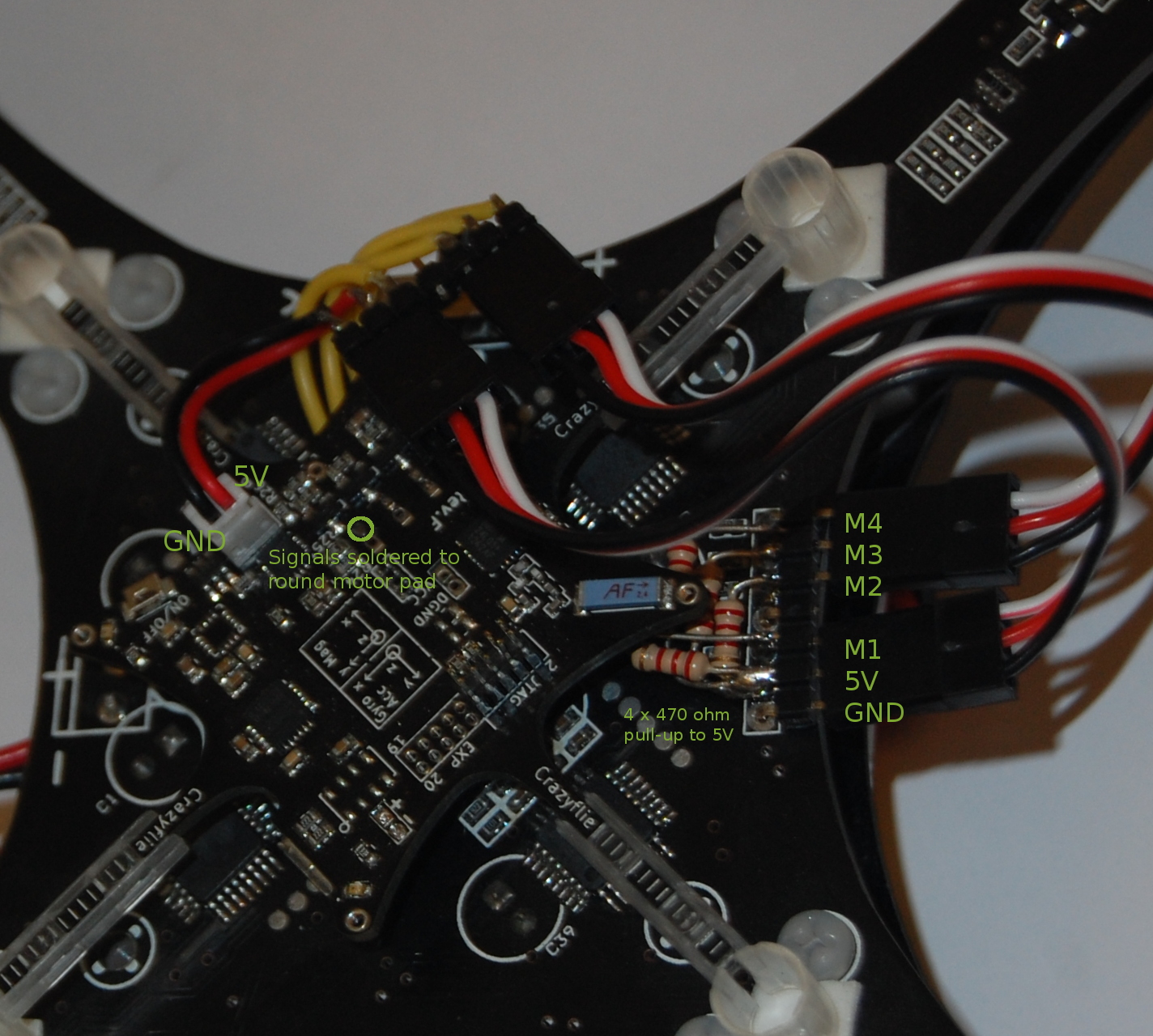
Now we only had to connect the Crazyflie to the BLMC:s on the frame. The BLMC electrical interface for the PWM signal is often a 5V interface but the Crazyflie runs on 2.8V. 2.8V would in most cases be treated as an high input and can probably be used directly but there is no simple way to connect this signal on the Crazyflie. Instead one way is to use the existing motor connectors and the pull-down capability that is already there. Then it is also possible to pull this signal to 5V with a resistor to get a 5V interface so this is what we did. To power the Crazyflie we took the connector of an old battery and soldered it the 5V output of the frame.
Now it was just a matter of testing it! However as size increases so does the potential damage it can make. We therefore took some precaution and tied it down. First we tested the stability on each axis using the stock values and it worked really well so we decided to not tune it further. The only issue was that suddenly one of the BLMC mosfets burnt. We replaced it and it worked again but don’t know why it burnt. Later when we flew it something was still strange so we have to investigate this.
We will upload the code as soon as it has been cleaned up. Please enjoy a short video of the journey :)
We hope everyone had a great holiday! We are really happy that some of you decided to join our holiday challenge. After looking though all of the submissions we finally decided on a result.
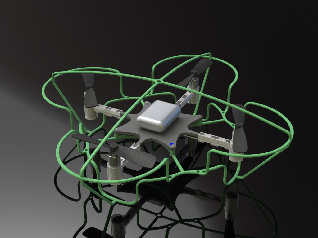
First of all there was the mechanical challenge of creating a hull or cover for the Crazyflie. When finding the winner we looked at features such as wight, design and manufacturing. After a long discussion we decided on Gottfried Dungl’s submission, the Crazysheild, that you can see below. Even though it might be tricky to manufacture/3D-print, it’s lighter than the other submissions while still being durable as he showed by crash simulations.
Crazyshield submitted by Gottfried.
Secondly there was the free-fall detection and recovery. For this challenge we only got one submission and it’s from Oliver Dunkley. That doesn’t matter since his solution works really well and has great potential. The implementation is done in the Crazyflie client, where both free-fall detection and recovery is done. There’s lots more information about this solution which we will post on the wiki or forum during the week. You can have a look at the code here.
Great job and big thanks to everyone that participated! Gottfried and Oliver will receive a Crazyflie 10-DOF kit and we have also decided to reward all others that participated with a little gift so check you email ;).