Previously we have been using off the shelf scales and other methods to measure characteristics, such as thrust or efficiency, of the Crazyflie products. We thought it was time to build something that is easier to use, more repeatable and tailored to our needs. Well, this has been on our wanted list for a long time, already back from when we did the RPM-deck. It was however first when Wolfgang visited us this winter that he nudged us over the edge so we finally allocated some time for it. We started off by buying some load cells and breakout boards to do something simple as a start, so we could at least measure thrust more easily. We actually started looking for off the shelf thrust stands but could not find anything suitable for the Crazyflie’s size. As is often the case here at Bitcraze, the project grew. Already before we had any load cells up and running I was designing a deck with RPM sensors, load cell amplifier and power meter. Now with the objective to easily do system identification. Therefor we named the deck the system-id deck.
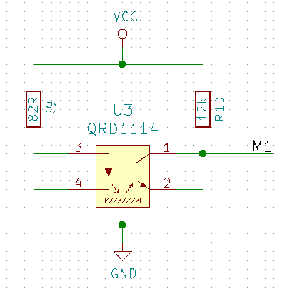
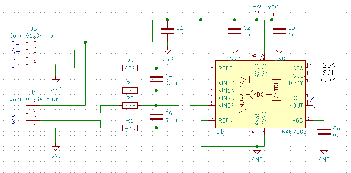
For the RPM sensors we used the same as on the RPM-deck, the QRD1114. They are not great as they need a reflective surface, this means adding white stickers or paint to black propellers, but they work well enough. The load cell amplifiers ended up to be the NAU7802 as it has a high accuracy and sample rate. For power metering we chose the new ACS37800 power monitoring IC that can handle up to 30A, this looked exiting.
The QRD1114 we wired the same way as previously done on the RPM-deck:
The NAU7802 was configured as per the datasheet suggestion and similarly to other open designs out there:
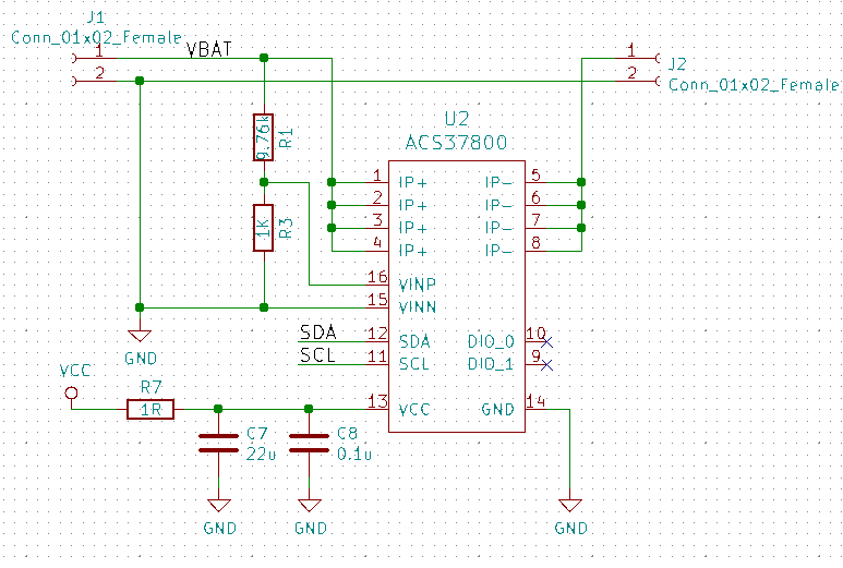
The ACS37800 was very new so the datasheet had to be used as the main information source. A bit tricky as this chip is mainly intended to measure mains supply, and we wanted to measure low voltage DC, which it said it could do…and in the end we managed to get it working.
We also added a buck/boost DC/DC that could provide a stable 3.3V from 2-5V input, just in case, as the ACS37800 is specified for this voltage and not the 3.0V the Crazyflie can supply.
The outcome
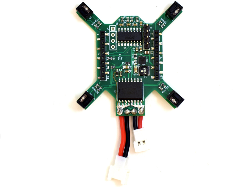
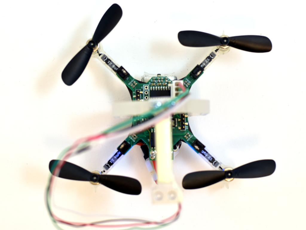
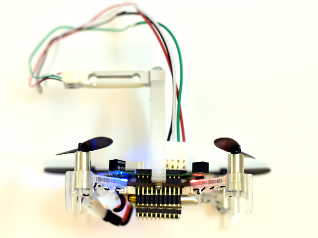
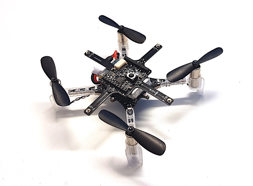
The PCB was designed as small as possible so it could be mounted on a Crazyflie 2.X and used while flying. A bonus would be if it could be used on a Bolt as well.
Here it is mounted on a Crazyflie 2.1 together with a 3D printed stand and load cell.
The load cell would then be mounted to a desk or similar so the the Crazyflie is mounted up-side down, pushing down on the load cell.
Software
The software, as often, took most of the time to make. Three major deck driver files was created, rpm.c, acs37800.c and loadcell_nau7802.c. Aside from these there where only small changes to make, like making it work when being up-side-down. The modifications have all been pushed to the dev-systemid branch for those that are interested. As for now we are mainly using the logging framework to transfer the data to the PC, which is quick and easy to setup and use, but writing to SD-card is also possible. The scripts for this can be found in the tools/sytem_id folder.
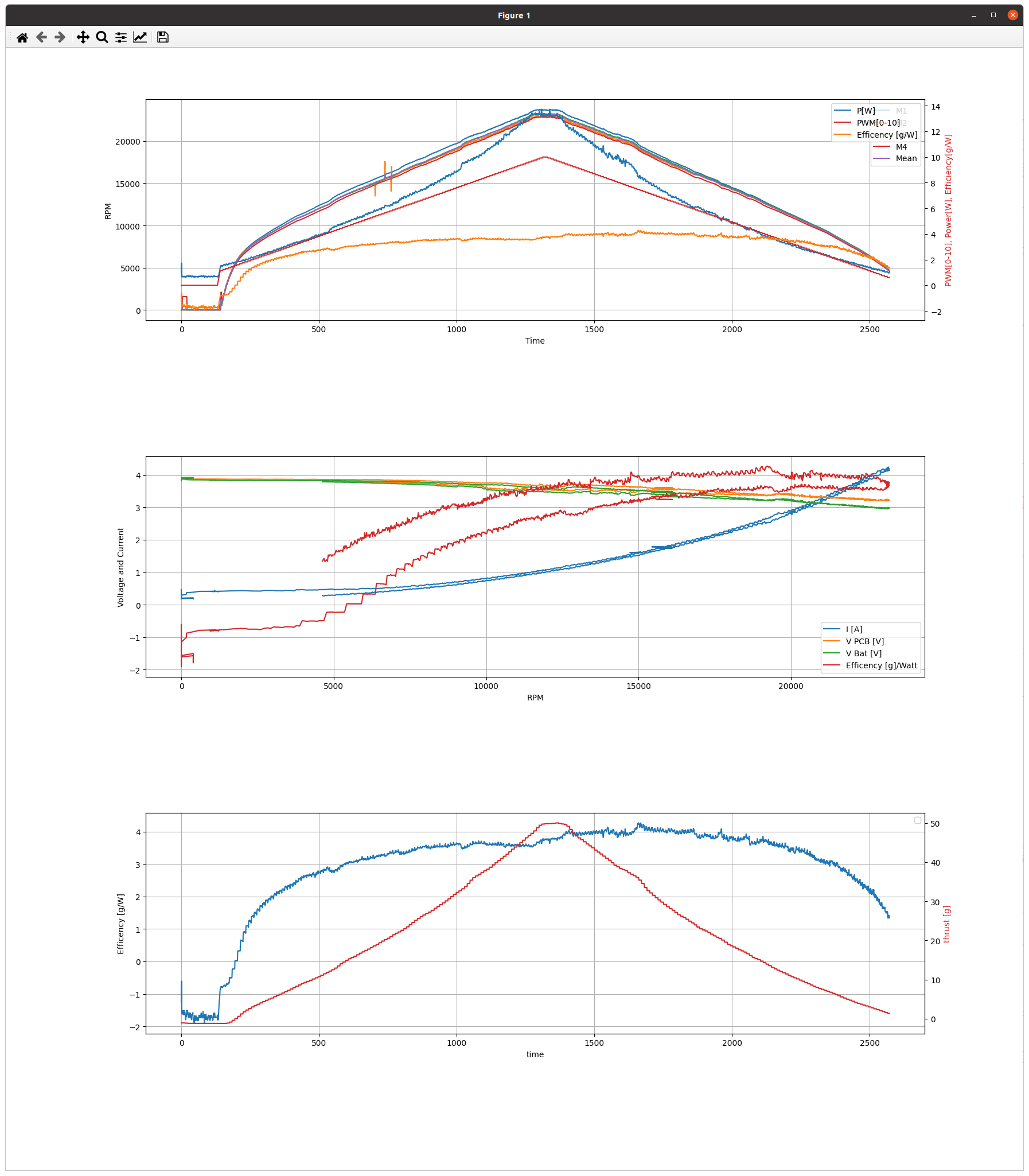
Remaining work is to test, gather and analyse more data. When we have done so, we will post more. Until then below is a sample of what it can measure. The data is taken with a ramping PWM from 0% – 100% – 0%. The added resistance of the extra wires and connectors are not taken into account, but the estimated efficiency of 4g/W is probably not that far off.
This week we have a guest blog post from Bart Duisterhof and Prof. Guido de Croon from the MAVlab, Faculty of Aerospace Engineering from the Delft University of Technology. Enjoy!
Tiny drones are ideal candidates for fully autonomous jobs that are too dangerous or time-consuming for humans. A commonly shared dream would be to have swarms of such drones help in search-and-rescue scenarios, for instance to localize gas leaks without endangering human lives. Drones like the CrazyFlie are ideal for such tasks, since they are small enough to navigate in narrow spaces, safe, agile, and very inexpensive. However, their small footprint also makes the design of an autonomous swarm extremely challenging, both from a software and hardware perspective.
From a software perspective, it is really challenging to come up with an algorithm capable of autonomous and collaborative navigation within such tight resource constraints. State-of-the-art solutions like SLAM require too much memory and processing power. A promising line of work is to use bug algorithms [1], which can be implemented as computationally efficient finite state machines (FSMs), and can navigate around obstacles without requiring a map.
A downside of using FSMs is that the resulting behavior can be very sensitive to their hyperparameters, and therefore may not generalize outside of the tested environments. This is especially true for the problem of gas source localization (GSL), as wind conditions and obstacle configurations drastically change the problem. In this blog post, we show how we tackled the complex problem of swarm GSL in cluttered environments by using a simple bug algorithm with evolved parameters, and then tested it onboard a fully autonomous swarm of CrazyFlies. We will focus on the problems that were encountered along the way, and the design choices we made as a result. At the end of this post, we will also add a short discussion about the future of nano drones.
Why gas source localization?
Overall we are interested in finding novel ways to enable autonomy on constrained devices, like CrazyFlies. Two years ago, we showed that a swarm of CrazyFlie drones was able to explore unknown, cluttered environments and come back to the base station. Since then, we have been working on an even more complex task: using such a swarm for Gas Source Localization (GSL).
There has been a lot of research focussing on autonomous GSL in robotics, since it is an important but very hard problem. The difficulty of the task comes from the complexity of how odor can spread in an environment. In an empty room without wind, a gas will slowly diffuse from the source. This can allow a robot to find it by moving up gradient, just like small bacteria like E. Coli do. However, if the environment becomes larger with many obstacles and walls, and wind comes into play, the spreading of gas is much less regular. Large parts of the environment may have no gas or wind at all, while at the same time there may be pockets of gas away from the source. Moreover, chemical sensors for robots are much less capable than the smelling organs of animals. Available chemical sensors for robots are typically less sensitive, noisier, and much slower.
Due to these difficulties, most work in the GSL field has focused on a single robot that has to find a gas source in environments that are relatively small and without obstacles. Relatively recently, there have been studies in which groups of robots solve this task in a collaborative fashion, for example with Particle Swarm Optimization (PSO). This allows robots to find the source and escape local maxima when present. Until now this concept has been shown in simulation [2] and on large outdoor drones equipped with LiDAR and GPS [3], but never before on tiny drones in complex, GPS-denied, indoor environments.
Required Infrastructure
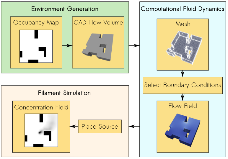
In our project, we introduce a new bug algorithm, Sniffy Bug, which uses PSO for gas source localization. In order to tune the FSM of Sniffy Bug, we used an artificial evolution. For time reasons, evolution typically takes place in simulation. However, early in the project, we realized that this would be a challenge, as no end-to-end gas modeling pipeline existed yet. It is important to have an easy-to-use pipeline that does not require any aerodynamics domain knowledge, such that as many researchers as possible can generate environments to test their algorithms. It would also make it easier to compare contributions and to better understand in which conditions certain algorithms work or don’t work. The GADEN ROS package [4] is a great open-source tool for modeling gas distribution when you have an environment and flow field, but for our objective, we needed a fully automated tool that could generate a great variety of random environments on-demand with just a few parameters. Below is an overview of our simulation pipeline: AutoGDM.
AutoGDM, a fully automated gas dispersion modeling (GDM) simulation pipeline.
First, we use a procedural environment generator proposed in [5] to generate random walls and obstacles inside of the environment. An important next step is to generate a 3D flowfield by means of computational fluid dynamics (CFD). A hard requirement for us was that AutoGDM needed to be free to use, so we chose to use the open-source CFD tool OpenFOAM. It’s used for cutting-edge aerodynamics research, and also the tool suggested by the authors of GADEN. Usually, using OpenFOAM isn’t trivial, as a large number of parameters need to be selected that require field expertise, resulting in a complicated process. Next, we integrate GADEN into our pipeline, to go from environment definition (CAD files) and a flow field to a gas concentration field. Other parts that needed to be automated were the random selection of boundary conditions, which has a large impact on the actual flow field, and source placement, which has an equally large impact on the concentration field.
After we built this pipeline, we started looking for a robot simulator to couple it to. Since we weren’t planning on using a camera, our main requirement was for the simulator to be efficient (preferably in 2D) so that evolutions would take relatively little time. We decided to use Swarmulator [6], a lightweight C++ robot simulator designed for swarming and we plugged in our gas data.
Algorithm Design
Roughly speaking, we considered two categories of algorithms for controlling the drones: 1) a neural network, and 2) an FSM that included PSO, with evolved parameters. Since we used a tiny neural network for light seeking with a CrazyFlie in our previous work, we first evolved neural networks in simulation. One of the first experiments is shown below.
A single agent in simulation seeking a light source using a tiny neural network.
While it worked pretty well in simple environments with few obstacles, it seemed challenging to make this work in real life with complex obstacles and multiple agents that need to collaborate. Given the time constraints of the project, we have opted for evolving the FSM. This also facilitated crossing the reality gap, as the simulated evolution could build on basic behaviors that we developed and validated on the real platform, including obstacle avoidance with four tiny laser rangers, while communicating with and avoiding other drones. An additional advantage of PSO with respect to the reality gap is that it only needs gas concentration and no gradient of the gas concentration or wind direction (which many algorithms in literature use). On a real robot at this scale, estimating the gas concentration gradient or the direction of a light breeze is hard if not impossible.
Hardware
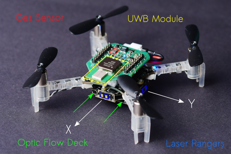
Our CrazyFlie needs to be able to avoid obstacles, execute velocity commands, sense gas, and estimate the other agent’s position in its own frame. For navigation, we added the flow deck and laser rangers, whereas for gas sensing we used a TGS8100 gas sensor that was used on a CrazyFlie before in previous work [7]. The sensor is lightweight and inexpensive, but accurately estimating gas concentrations can be difficult because of its size. It tends to drift and needs time to recover after a spike in concentration is observed. Another thing we noticed is that it is possible to break them, a crash can definitely destroy the sensor.
To estimate the relative position between agents, we use a Decawave Ultra-Wideband (UWB) module and communicate states, as proposed in [8]. We also use the UWB module to communicate gas information between agents and collaboratively seek the source. The complete configuration is visible below.
A 37.5 g nano quadcopter, capable of fully autonomous waypoint tracking, obstacle avoidance, relative localization, communication and gas sensing.
Evaluation in Simulation
After we optimized the parameters of our model using Swarmulator and AutoGDM, and of course trying many different versions of our algorithm, we ended up with the final Sniffy Bug algorithm. Below is a video that shows evolved Sniffy Bug evaluated in six different environments. The red dots are an agent’s personal target waypoint, whereas the yellow dot is the best-known position for the swarm.
Sniffy Bug evaluated in Swarmulator environments.
Simulation showed that Sniffy Bug is effective at locating the gas source in randomly generated environments. The drones successfully collaborate by means of PSO.
Real Flight Testing
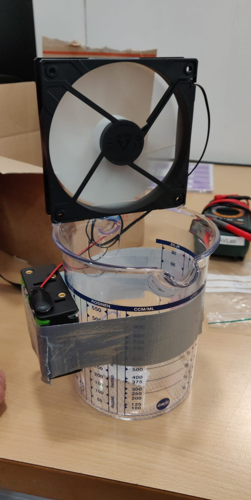
After observing Sniffy Bug in simulation we were optimistic, but unsure about performance in real life. First, inspired by previous works, we disperse alcohol through the air by placing liquid alcohol into a can which is then dispersed using a computer fan.
Dispersion of liquid alcohol in flight tests.
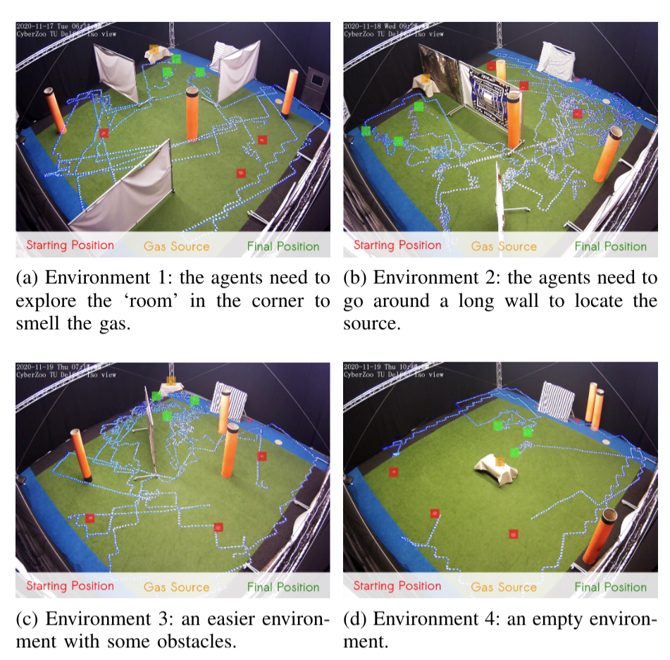
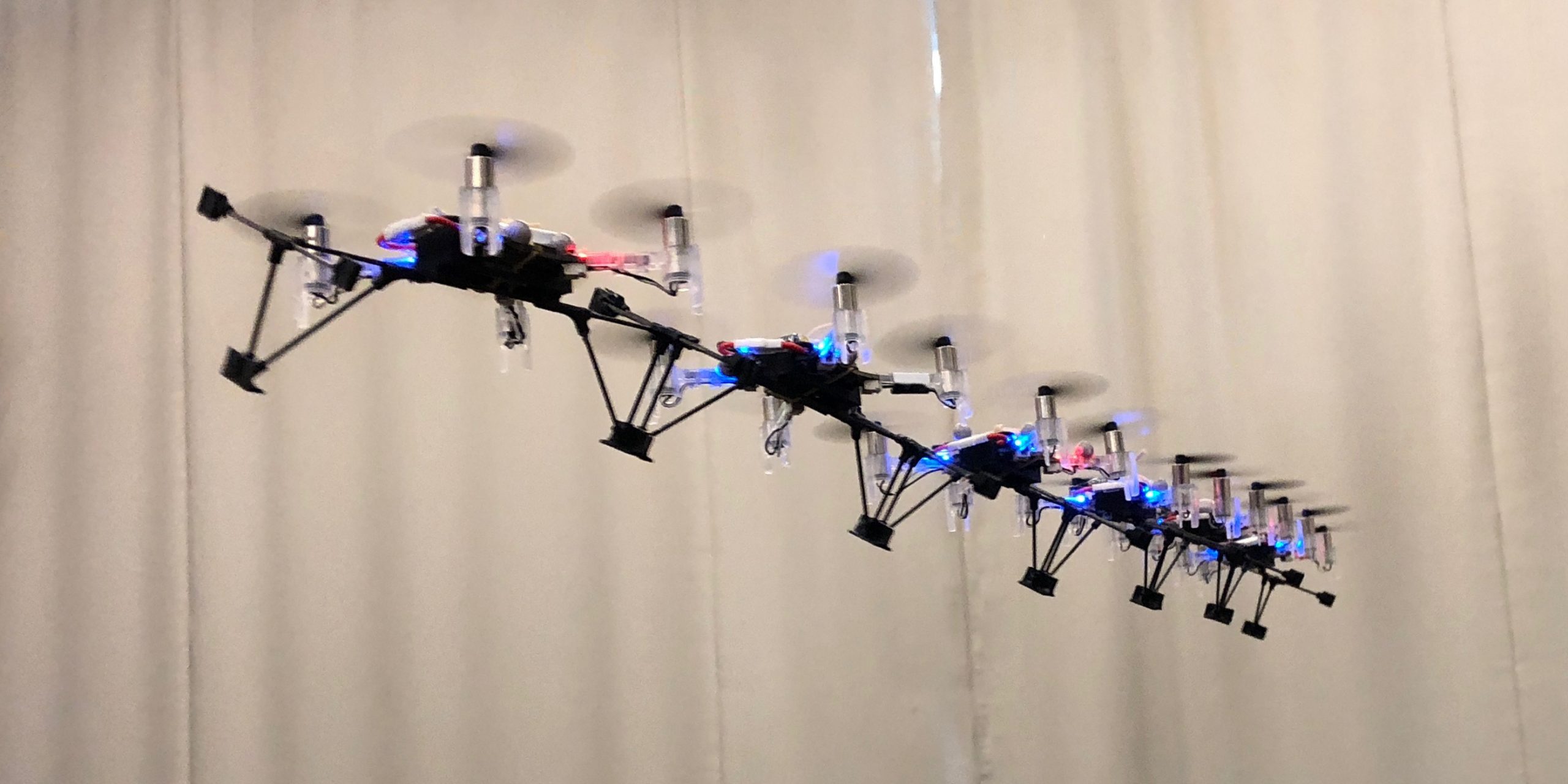
We test Sniffy Bug in our flight arena of size 10 x 10 meters with large obstacles that are shaped like walls and orange poles. The image below shows four flight tests of Sniffy Bug in cluttered environments, flying fully autonomously, i.e., without the help from any external infrastructure.
Time-lapse images of real-world experiments in our flight arena. Sniffy was evaluated on four distinct environments, 10 x 10 meters in size, seeking a real isopropyl alcohol source. The trajectories of the nano quadcopters are clearly visible due to their blue lights.
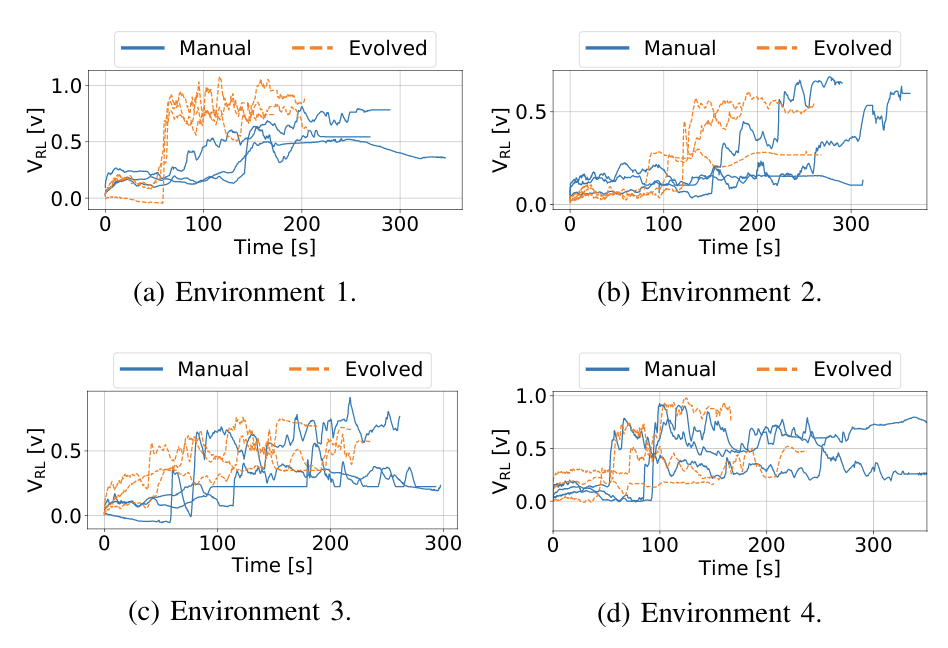
In the total of 24 runs we executed, we compared Sniffy Bug with manually selected and evolved parameters. The figure below shows that the evolved parameters are more efficient in locating the source as compared to the manual parameters.
Maximum recorded gas reading by the swarm, for each time step for each run.
This does not only show that our system can successfully locate a gas source in challenging environments, but it also demonstrates the usefulness of the simulation pipeline. The parameters that were learned in simulation yield a high-performance model, validating the environment generation, randomization, and gas modeling parts of our pipeline.
Conclusion and Discussion
With this work, we believe we have made an important step towards swarms of gas-seeking drones. The proposed solution is shown to work in real flight tests with obstacles, and without any external systems to help in localization or communication. We believe this methodology can be extended to larger environments or even to 3 dimensions, since PSO is a robust, multi-dimensional heuristic search method. Moreover, we hope that AutoGDM will help the community to better compare gas seeking algorithms, and to more easily learn parameters or models in simulation, and deploy them in the real world.
To improve Sniffy Bug’s performance, adding more laser rangers will definitely help. When working with only four laser rangers you realize how little information it actually provides. If one of the rangers senses a low value it is unclear if a slim pole or a massive wall is detected, adding inefficiency to the algorithm. Adding more laser rangers or using other sensor modalities like vision will help to avoid also more complex obstacles than walls and poles in a reliable manner.
Another interesting discussion can be held on the hardware required for real deployment. When working with 40 grams of maximum take-off weight, the sensors and actuators that can be selected are limited. For example, the low-power and lightweight flow deck works great but fails in low-light scenarios or with smoke. Future work exploring novel sensors for highly constrained nano robots could really help increase the Technological Readiness Level (TRL) of these systems.
Finally, this has been a really fun project to work on for us and we can’t wait to hear your thoughts on Sniffy Bug!
Li-Ion batteries have packed more energy per gram for a long time compared to Li-Po batteries. The problem for UAV applications has been that Li-Ion can’t deliver enough current, something that is starting to change. Now there are cells that are supposed to be able to deliver 30-35A continuously in the 18650 series, at least according to the specs. Therefor we thought it was time to do some testing and decided to build a 1 cell Li-Ion drone using the Crazyflie Bolt as base.
Since a 18650 battery is 18mm in diameter and 65mm long, the size would affect the design but we still wanted to keep the drone small and lightweight. The battery is below 20mm wide which means we can run the deck connectors around it, that is nice. We chose to use our 3D printer to build the frame and use off the shelf ESCs, motors and props. After a couple of hours of research we selected 3″ propellers, 1202.5 11500kv motors and tiny 1-2s single ESCs for our first prototype.
Parts list:
1 x Custom designed 130mm 3D printed frame
1 x Crazyflie Bolt flight controller
4 x Eachine 3020 propeller (2xCW + 2xCCW)
4 x Flywoo ROBO RB 1202.5 11500 Kv motors
4 x Flash hobby 7A 1-2S ESC
1 x Li-Ion Sony 18650 VTC6 3000mAh 30A
Screws, anti vib. spacers, zipties, etc.
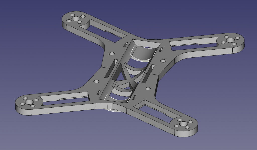
The custom designed frame was developed in iterations, and can still be much improved, but at this stage it is small, lightweight and rigid enough. We wanted the battery to be as central as possible while keeping it all compact.
Prototype frame designed in FreeCAD.
Assembly and tuning
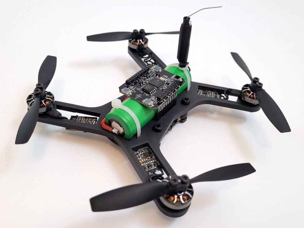
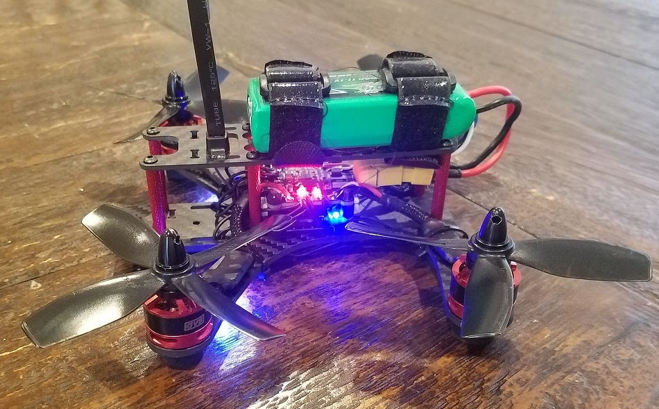
The 3D printed frame came out quite well and weighed in at 13g. After soldering the bolt connectors to the ESCs, attaching motors and props, adjusting battery cable and soldering a XT30 to the Li-Ion battery it all weighed ~103g and then the battery is 45g of these. It feels quite heavy compared to the Crazyflie 2.1 and we had a lot of respect when we test flew it the first time. Before we took off we reduced the pitch and roll PID gains to roughly half and luckily it flew without problems and quite nicely. Well it sounds a lot but that is kind of expected. After increasing the gains a bit we felt quite pleased with:
This would be good enough for what we really wanted to try, the endurance with a Li-Ion battery. A quick measurement of the current consumption at hover, 5.8A, we estimated up to ~30 min flight time on a 3000mAh Li-Ion battery, wow, but first a real test…
Hover test
For the hover test we used lighthouse 2 which is starting to work quite well. We had to change the weight and thrust constants in estimator_kalman.c for the autonomous flight to work:
#define CRAZYFLIE_WEIGHT_grams (100.0f)

//thrust is thrust mapped for 65536 <==> 250 GRAMS!
#define CONTROL_TO_ACC (GRAVITY_MAGNITUDE*250.0f/CRAZYFLIE_WEIGHT_grams/65536.0f)
After doing that and creating a hover script that hovers at 0.5m height and was set to land when the voltage reached 3.0V. We leaned back with excitement, behind a safety net, and started the script… after 19 min it landed… good but not what we hoped for and quite far from the calculated 30 min. Maybe Li-Ion isn’t that good when it needs to provide more current…? A quick internet search and we could find that Li-Ion can run all the way down to 2.5V, but we have to stop at 3.0V because of electronics and loosing thrust, so we are missing quite a bit of energy… Further investigations are needed.
Lighthouse 2 flight test
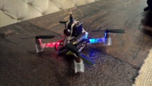
As a final test we launched some flight scripts to fly in a square and in a spiral so we would get a feel for Lighthouse 2 + Bolt with PID controller combination. We think it turned out quite nicely, and this with almost no optimization effort:
Summary
Li-Ion felt like it could be a game changer when it comes to flight time but was not as promising as we hoped for. It doesn’t mean we can’t get there though. More research and development is required.
Modular robotics implies in general flexibility and versatility to robots. In theory, you could design a modular robot basically on the way you would want it to be, by simply adding or removing modules from the already existing robot. Changing the robot configuration by adding more individuals, generally increases the system redundancy, meaning that now, there are probably many different ways to achieve a specific goal. From a naive standard point of view, more modules could imply in practice more robustness due to this redundancy. In fact, it does get more robust by the cost of becoming more complex, and probably harder to control. Added to that, other issues may arise when you take into account that your modular robot is flying, and how physical properties and actuation scales as the number of modules grow.
In the GRASP Laboratory at the University of Pennsylvania, one of our focuses is to allow robots to achieve a specific task. In this work, we present ModQuad-DoF, which is a modular flying platform that enlarges the configuration space of modular flying structures based on quadrotors (crazyflies), by applying a new yaw actuation method that relies on the desired roll angles of each flying vehicle. This research project is coordinated by Professor Mark Yim , and led by Bruno Gabrich (PhD candidate).
Scaling Modular Robots
Scaling modular robots is a very challenging problem that usually limits the benefits of modularity. The sum of the performance metrics (speed, torque, precision etc.) from each module usually does not scale at the same rate as the conglomerate physical properties. In particular, for ModQuad, saturation from individual motors would increase as the structures became larger leading to failure and instability. When conglomerate systems scale up in the number of modules, the moment of inertia of the conglomerate often grows faster than the increase in thrust capability for each module. For example, the increase in the moment of inertia for a fifth module added to four modules in a line can be approximated by the mass of the module times half the distance to the center squared. This quadratic increase gives us the intuition that the required yaw actuation grows faster than the actuation authority.
Yaw Actuation
An inherit characteristic of quadrotors is to have their yaw controlled by the drag moments from each propeller. For ModQuad as more modules are docked together, a decreased controllability in yaw is noticed as the structure becomes larger. In a line configuration the structure’s inertia grows quadratically with the distance of each module to the structure center of mass. On the other hand the drag moments produced scales linearly with the number of modules.
The new yaw actuation method relies on the fact that each quadrotor is capable to generate an individual roll enabled by our new cage design. By working in coordinated manner, each crazyflie can then generate structure moments from moment arms provided by the propellers given its roll and its distance from the structure’s center of mass.
Cage Design
The Crazyflie 2.0 is the chosen platform to enable thrust and attitude to the individual modules. The flying vehicle measures 92×92×29 mm and weights 27 g while its battery lasts around 4 minutes for the novel design proposed. In this work the cage performs as pendulum relative to the flying vehicle. The quadrotor is joined to the cage through a one DOF joint. The cages are made of light-weight materials: ABS for the 3-D printed connectors and joints, and carbon fiber for the rods.
Although the flying vehicle does not necessarily share same orientation as the cage, the multiple connected cages do preserve same orientation relative to each other. With the purpose of allowing such behavior, we used Neodymium Iron Boron (NdFeB) magnets as passive actuators to enable rigid cage connections. Docking is only allowed at the back and front face of the modules, and each one of these faces contains four magnets. Those passive actuators have dimensions of 6.35 × 6.35 × 0.79 mm with a bonding force of 1 kg.
Structure Flying Performance
Conclusions
ModQuad-DoF is a flying modular robotic structure whose yaw actuation scales with increased numbers of modules. ModQuad-DoF has a one DOF jointed cage design and a novel control method for the flying structure. Our new yaw actuation method was validated conducting experiments for hovering conditions. We were able to perform two, four and, six modules cooperatively flying in a line with yaw controllability and reduced loss in thrust. In future work we aim to explore the structure controllability with more robots in a line configuration, and exploring different solutions for the desired roll angles. Possibly, with more modules in the structure, only a few would be required to roll in order to maintain a desired structure yaw. Given that, we could explore the control allocation for each module in a specific structure configuration, and dependent on its desired behavior. Further, structures that are not constrained to a line will also be tested using the basis of the controller proposed in this work.
Who knew propellers would be that hard? Already from the very beginning with the Crazyflie 1.0, we had problems with very unbalanced propellers resulting in reduced flight performance. The fix at that time was to manually test and sort out the bad propellers. This worked well until the manufacturer’s injection mould got too worn down and we had to reject a lot of propellers. The manufacturer didn’t want to continue selling us the propellers unless we accepted them all. The hunt for a new manufacturer begun and after trying several, we finally, just in time for the Crazyflie 2.1, found one that could deliver well balanced propellers.
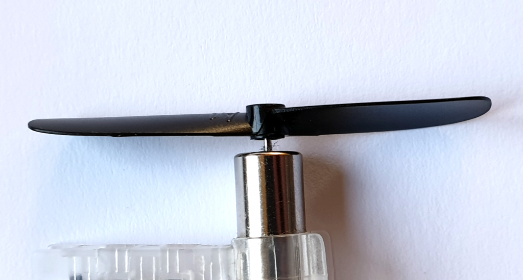
That could have been the end of a happy story but recently we found out that the new propellers tend to break too easily. The root cause seems to be that the center hole is too tight, causing tension in the plastic which makes it more fragile and prone to break.
Typically broken propeller
We don’t fully understand when this started but it looks like it was not that frequent in the beginning when the Crazyflie 2.1 was released and that it has increased from the batch manufactured in the end of July 2019. We don’t have data on how many propellers are bad but our estimation is around 20-40% and it is booth CW and CCW propellers. It also includes the spare part bundles manufactured in the second half of 2019.
Currently out main focus is to fix this propeller manufacturing issue. As soon as we have done so, we will lunch some form of replacement propeller program so that those of you that have gotten many bad propellers can get new ones for free. We don’t have any time estimate right now, and due to the world covid-19 crisis we have a feeling it can take a while. We are very sorry about this!
Insert propeller so it sits firmly, but not further
Workaround
There is an easy, but not ideal, workaround for this and that is to not push the propeller all the way down on the shaft. Instead stop when force is getting high and it holds the propeller in place. This will prevent the tension in the propeller to become big enough to break.
For those that have ordered after the 16th of March we have fixed the propellers by drilling the center hole slightly larger. This solves the problem for those units until we have fixed the root cause at the manufacturer.
I started working with the Crazyflie 2.0 in 2015. I was interested in learning how to program a quadcopter, and the open-source nature of the Crazyflie’s hardware and software was the perfect starting point.
Shortly after, I discovered the world of FPV and the thrill of flying with a bird’s eye view. My journey progressed from rubber-banding an all-in-one camera/VTX to my Crazyflie, to building a 250mm racing quad (via the BigQuad deck), and into the world of Betaflight (including bringing Betaflight support to the Crazyflie hardware).
FPV for Beginners ;)
BigQuad Build
Naturally, the announcement of the Bolt (then known as the RZR) piqued my interest, and the folks at Bitcraze graciously allowed me early hands-on with the product.
This post details my progress towards building out a FPV-style drone on top of the Crazyflie Bolt.
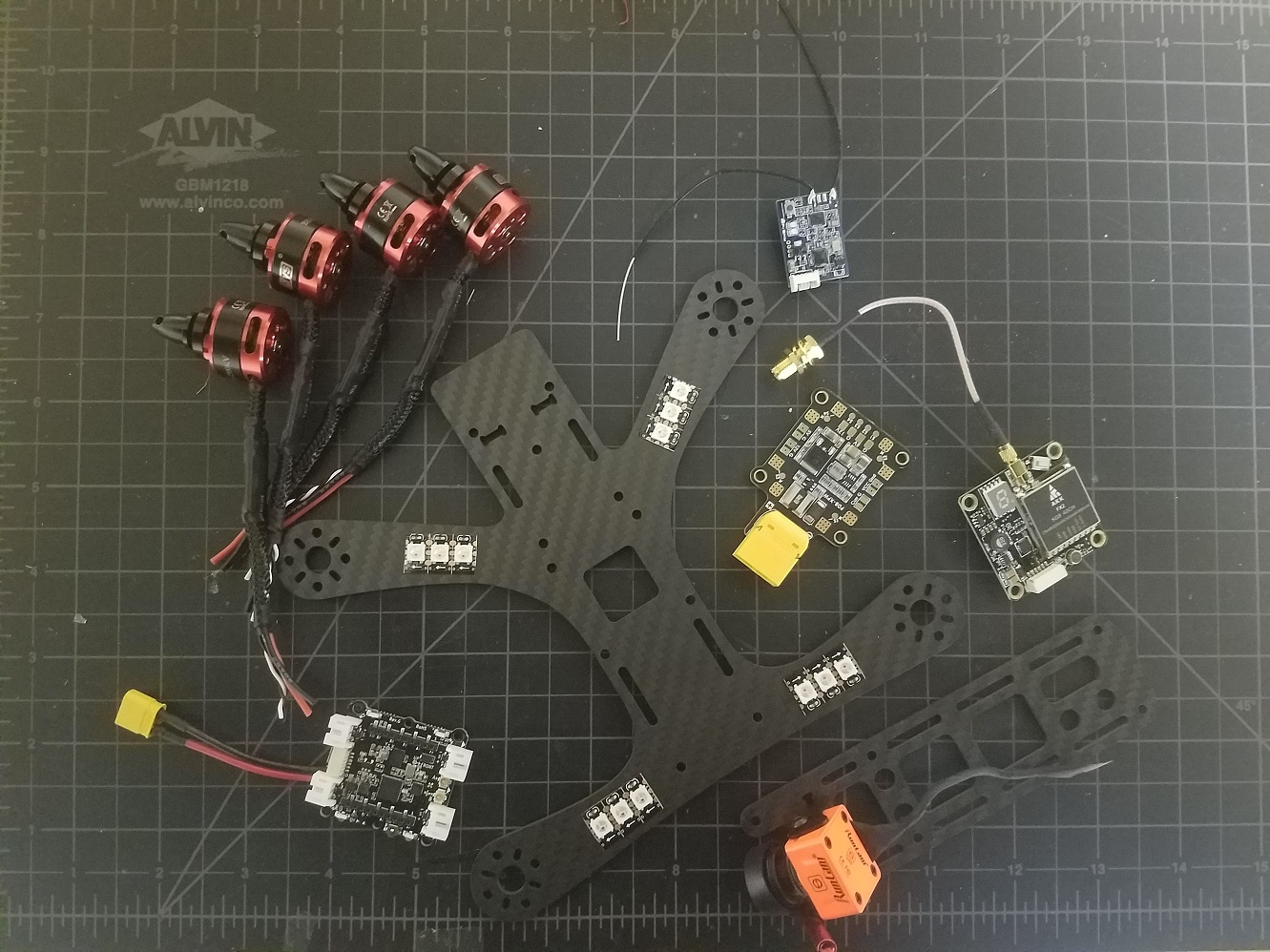
Component List
The FPV community has come a long way since 2015. What once was a very complicated process is now well documented and similar to building a PC (well, with some soldering). For latest details on the specifics of building FPV drones, I recommend resources such as Joshua Bardwell or the r/Multicopter subreddit.
Turns out I had enough components lying around for a 4-inch (propeller diameter) build based on 3S (3 cell) LiPo batteries. Again, there’s nothing special about these parts (in fact they’re all out of date). Take this list as a guide, and do your own research.
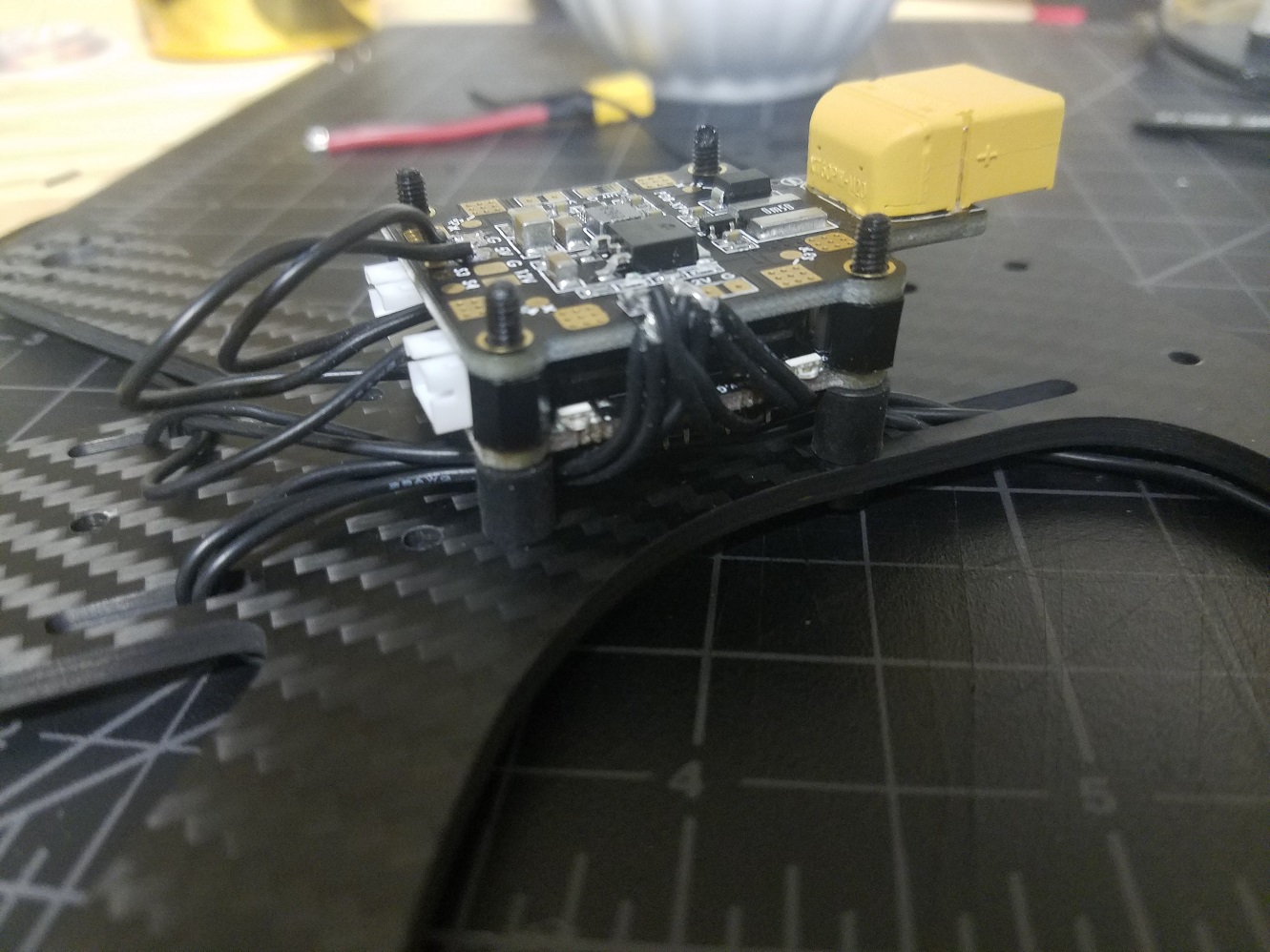
PDB (Power Distribution Board): This is a circuit board that produces regulated voltages from an unregulated LiPo battery. The Bolt has built-in regulators but is only rated up to an 8A current draw per motor. My 4 inch propellers will certainly draw more than 8A, and so an external PDB is required (plus having dedicated 12V and 5V supplies is nice for peripherals).
4x DYS 1806 Brushless Motors: Brushless motors use magnetic pulses to rotate a motor bell (distinct from brushed motors found on the regular Crazyflie).
4x DYS 20A BLHeli_S ESCs (Electronic Speed Controller): This is a piece of circuitry that accepts a logic-level control signal and applies direct battery power to motor coils to make a brushless motor spin. They have to be rated for the current draw expected by the battery+propeller combination.
Tweaker (by Shendrones) Frame: I’ve been wanting to build a quad around this frame, and the large square hole is interesting for the Bolt (more on that later). One thing to keep in mind is this is an ‘H’ style frame. That is, it’s longer than it is wide, so flight will not be perfectly symmetrical. If you’re interested in building a larger Crazyflie and not so interested in FPV, you’ll definitely want a symmetrical ‘X’ style frame.
Camera + VTX: For a full FPV setup, you’ll need a camera and a video transmitter. For the most part these run completely independently of the flight controller and so I’ll omit them from this article — what I’ve shown in the picture above is horribly out of date anyway.
RX: Radio receiver. For longer range flights and reduced latency it may be a good idea to use an external radio and UART-based receiver with diversity antennas. However, some specific work went in to the Bolt’s antenna design, so I’ll be sticking with the on-board NRF51 and external antenna.
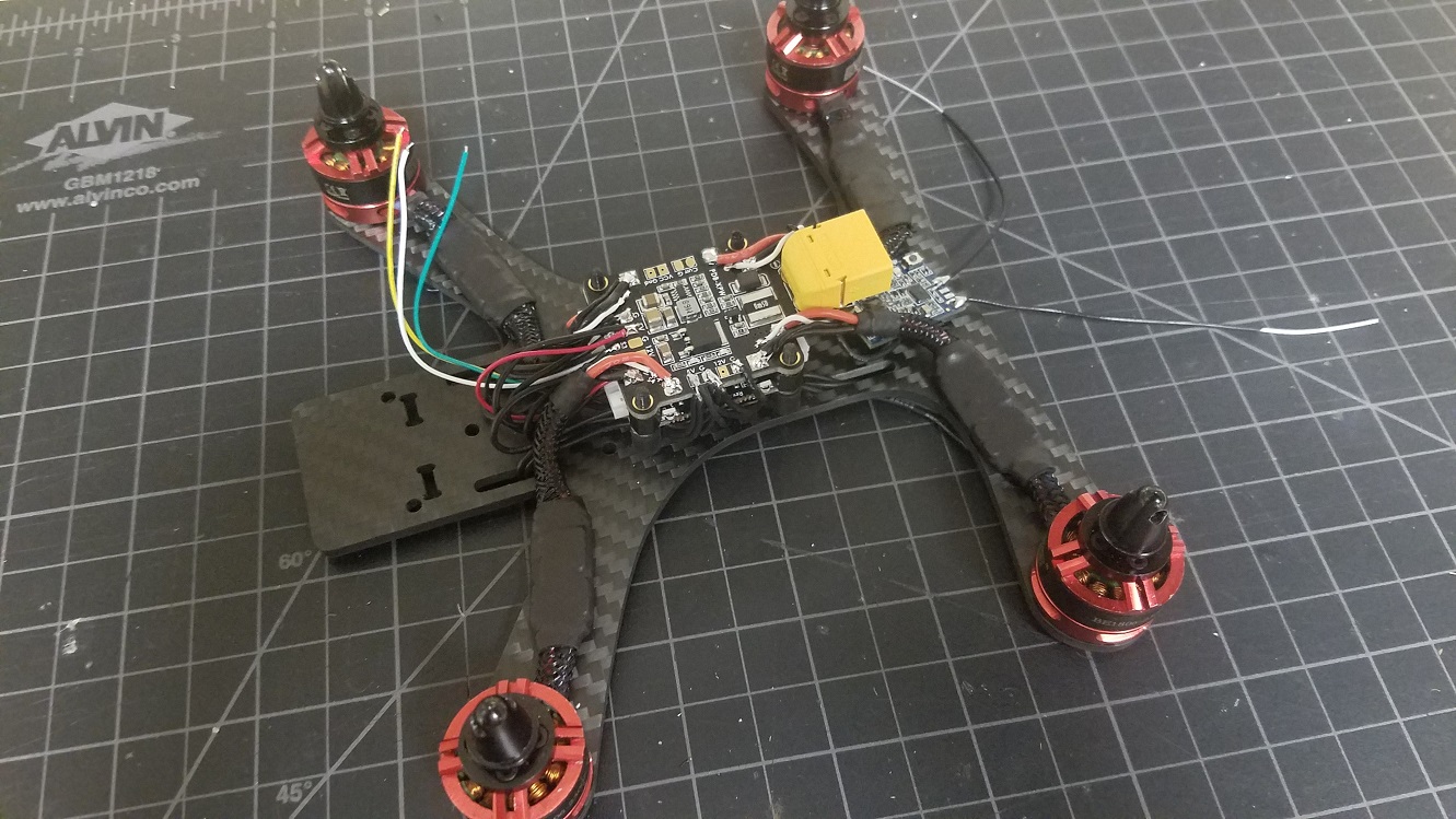
Again, there are hundreds of fantastic guides on the web that detail how to build an FPV quadcopter. Instead of trying to create another, here are some notes specific to my Bolt build.
Expansion Decks
Since the Bolt is pin compatible with the Crazyflie, I thought it would be interesting to try and take advantage of a couple existing Crazyflie expansion decks in my build: The LED Ring Deck, the Flow Deck v2, and the Micro SD Card Deck.
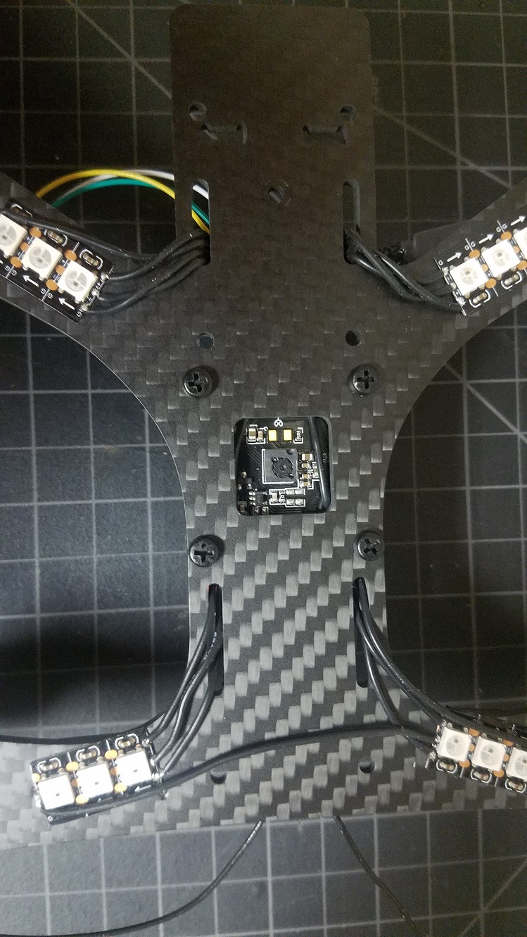
The LED Ring Deck
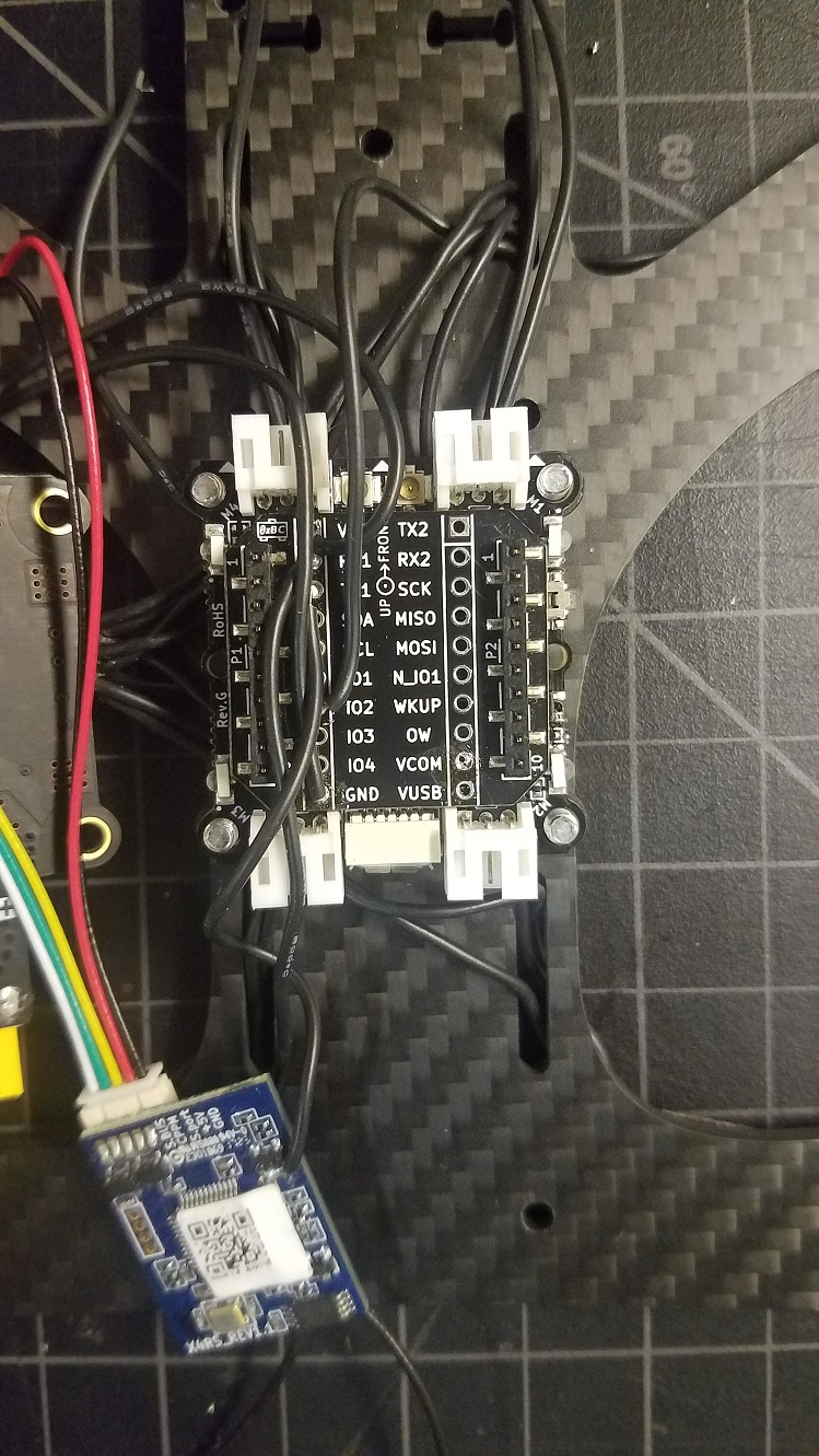
The LEDs were the most hands-on feature to enable. Rather than simply attaching the LED ring inside the frame, I mounted a series of WS2812B lights to the underside of my frame’s arms. The LED Ring Deck consists of 12 LEDs connected in series — so I put three LEDs on each arm of the frame and wired them up in a daisy-chain.
Finally, I soldered the lead to IO_2 (the same that’s used by the LED Ring Deck) on a Breakout Deck.
Since this isn’t the official LED Ring Deck, there’s no OW memory ID. The deck must be force-enabled by specifying a compile flag in your tools/build/make/config.mk file:
CFLAGS += -DDECK_FORCE=bcLedRing
With the custom firmware, the under-arm LEDs work just like the LED Ring Deck (other than the lack of front-facing LEDs).
Micro SD Card Deck
Most popular flight controllers feature flash storage or SD card slots for data logging. The FPV community uses storage to log sensor data for PID tuning and debugging. Naturally, this deck is a good fit on my Bolt build, and requires no additional modification.
Flow Deck (v2)
Remember my interest in the square cutout on my frame of choice? That, and my unorthodox choice to mount the Bolt board below my PDB, means I can theoretically use the bottom-attached Flow Deck to achieve some lateral stabilization while close to the ground. In theory, the VL53L1x ranger should work outdoors thanks to its usage of 940nm light as opposed to 850nm.
Note: This photo also shows the daisy chain wire connecting banks of LEDs in series
Other Build Tips
It’s good practice to soft mount flight controllers to minimize transferring motor/prop vibrations into the IMU. I used these to isolate the flight controller from the frame — not perfect, but better than a rigid mount.
The receiver antenna must be mounted clear of the carbon fiber frame and electronics. I like to use a heavy duty zip tie and attach the antenna with heat shrink.
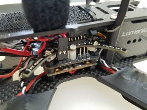
The Bolt can be powered from a 5v regulator on your PDB, but if you want to take advantage of the VBat sensor it should be powered from the raw battery leads instead. However, most ESCs support active breaking (ability to slow/stop the propellers on demand). Active breaking is known to produce a lot of back-voltage, which can damage some circuits. To be safe, since I’m using a 3S battery (12.6V when fully charged, 11.1V when depleted) I chose to power the Bolt off a regulated 12V supply from my PDB. This way, the PDB’s regulator will filter out voltage spikes and help protect the Bolt. Readings won’t be accurate at the higher range, but what really matters for a voltage sensor is to know when to land.
Results
It works! There is work needed to improve flight, though:
Control tuning is required. The powerful brushless motors respond much quicker than brushed motors, and so many of the PID and/or Kalman parameters are too aggressive or just non-optimal.
Stabilization with the Flow deck does not work — I haven’t spent much time debugging but my guess is it’s either due to the Kalman tuning, or problems with the VL53L1x depth working outdoors (which also impacts the flow measurements)
Betaflight Support: Betaflight has no driver for the BMI088 IMU used on the Crazyflie Bolt or the Crazyflie 2.1.
Safety Features: Brushless quads are very dangerous and can cause serious injuries. It’d be good to implement a kill-switch and a more aggressive failsafe in the firmware to prevent flyaways.
All in all, this was an enjoyable project and I’m excited to see some autonomous brushed quads coming out of the Crazyflie community!
This week we have a guest blog post from Joseph La Delfa.
DroneChi is a Human Drone interaction experience that uses the Qualisys motion capture system that enables the Crazyflie to react to movements of your body. At the Exertion Games Lab in Melbourne Australia, we like to design new experiences with technology where the whole body can be the controller and is involved in the experience.
When we first put these two technologies together we realised two things.
It was super easy to keep your attention on a the drone as it flew around the room reacting to your movements.
As a result it was also really easy to reflect on and refine ones own movements.
We thought this was like meditation meditated by a drone, and wanted to investigate how to further enhance this experience through design. We thought the smooth movements were especially mesmerising and so I decided to take beginner Tai Chi lessons; to get an appreciation of what it felt like to move like a Tai Chi student.
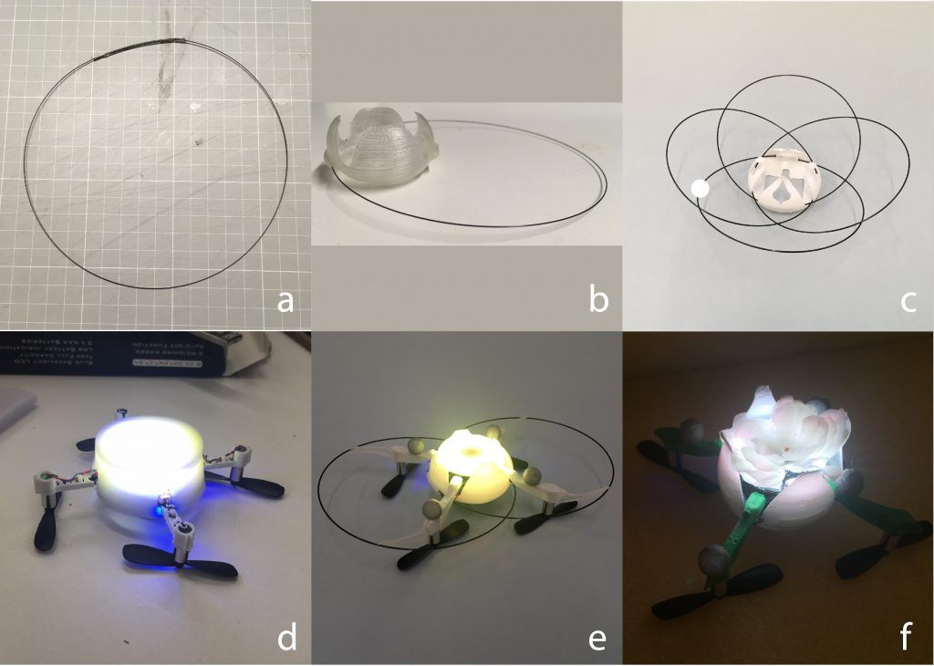
We undertook an 8 month design program where we simultaneously designed the form and the interaction of the Crazyflie. The initial design brief was pretty simple, make it look and feel light, graceful and from nature. In Tai Chi you are asked all the time to imagine a flower, the sea or a bird as you embody its movements, we wanted to emulate these experiences but without verbal instruction. Could a drone facilitate these sorts of experiences through it’s design?
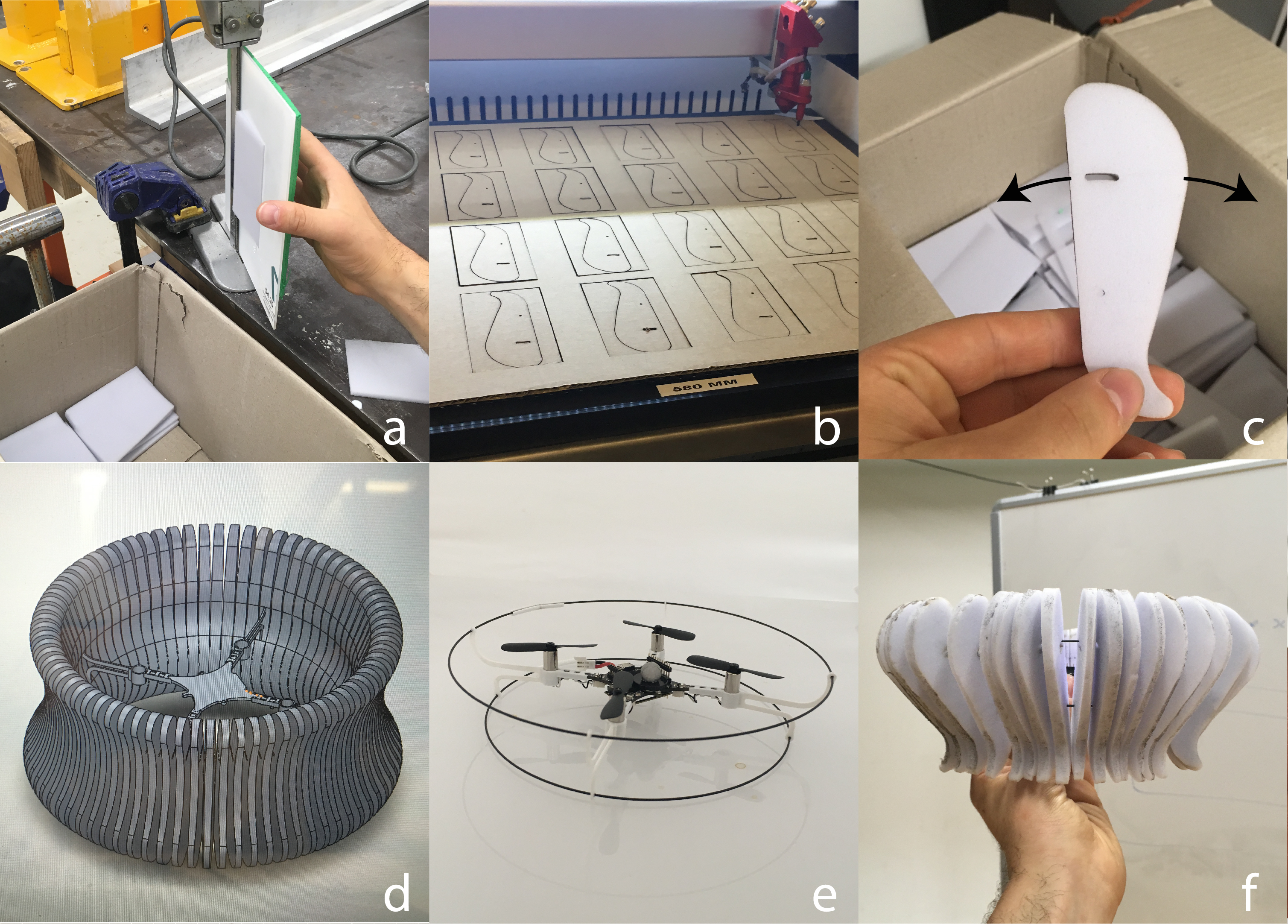
We will present a summarised version of how the form and the interaction came about. Starting with a mood board, we collated radially symmetrical forms from nature to match a drone’s natural weight distribution.
We initially went with a jelly fish, hoping to emulate their “push gliiide” movement by articulating laser cut silhouettes (see fig c). This proved incredibly difficult, after searching high and low for a foam that was light enough for the Crazyflie to lift, we just could not get it to fly stable.
However, we serendipitously fell into the flower shape by trying to improve how we joined the carbon rods together in a loop (fig b below). By joining them to the main hull we realised it looked like a petal! This set us down the path of the flower, we even flipped the chassis so that the LED ring faced upwards (cheers to Tobias for that firmware hack).
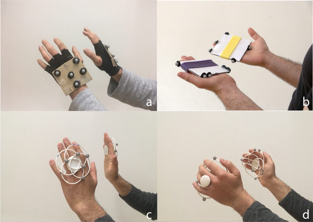
Whilst this was going on we were experimenting with how to actually interact with the drone. Considering the experience was to be demonstrated at a major conference we decided to keep the tracking only to the hands, this allowed quick change overs. We started with cardboard pads, experimented with gloves but settled on some floral inspired 3D printed pads. We were so tempted to include the articulation of the fingers but decided against it to avoid scope creep! Further to this, we curved the final hand pads (fig d) to promote the idea of holding the drone, inspired by a move in Tai Chi called “holding the ball”.
As a beginner practicing Tai Chi I was sometimes overwhelmed by the number of aspects of my movement that constantly needed monitoring, palms out, heel out, elbow slightly bent, step forward etc. However in brief moments it all came together and I was able to appreciate the feelings of these movements as opposed to consciously monitoring them. We wanted this kind of experience when learning DroneChi so we devised a way of mapping the drone to the body to emulate this. After a few iterations we settled on the “mid point” method as seen below.
The drone only followed the midpoint (blue dot above) if it was within .2m of it. If it was outside of this range it would float away slowly from the participant. This may seem like a lot, but with little in the way of visual guidance (eg a laser pointer or an augmented display) a person can only rely on the proprioceptive feedback from their own body. We used the on board LED ring on the drone to let the person know at least when they are close, but that is all the help they got. As a result this takes a lot of concentration to get right!
In the end we were super happy with the final experience, in the study participants reported tuning into their bodies when using the drone, as well as experiencing a unique sort of relationship to the drone; not entirely like a pet and also like an extension of the body. We will be investigating both findings from the study through the design and testing of a new system on the Crazyflie. We see this work contributing to more intimate designs for human drone interactions as well as a being applicable to health contexts such as rehabilitation.
We have briefly mentioned the Active marker deck earlier in our blog and in this post we will describe how it works and what it is all about.
The Active marker deck is a result of our collaboration with Qualisys, a Swedish manufacturer of high end optical tracking systems. Optical tracking systems are often referred to as motion capture (mocap) systems and are using cameras to track markers on an object. By using multiple cameras it is possible to calculate the 3D position of the markers and the object they are attached to with very high precision and accuracy. It is common to use mocap systems in robotic labs to track the position and orientation of robots, for instance quadrotors.
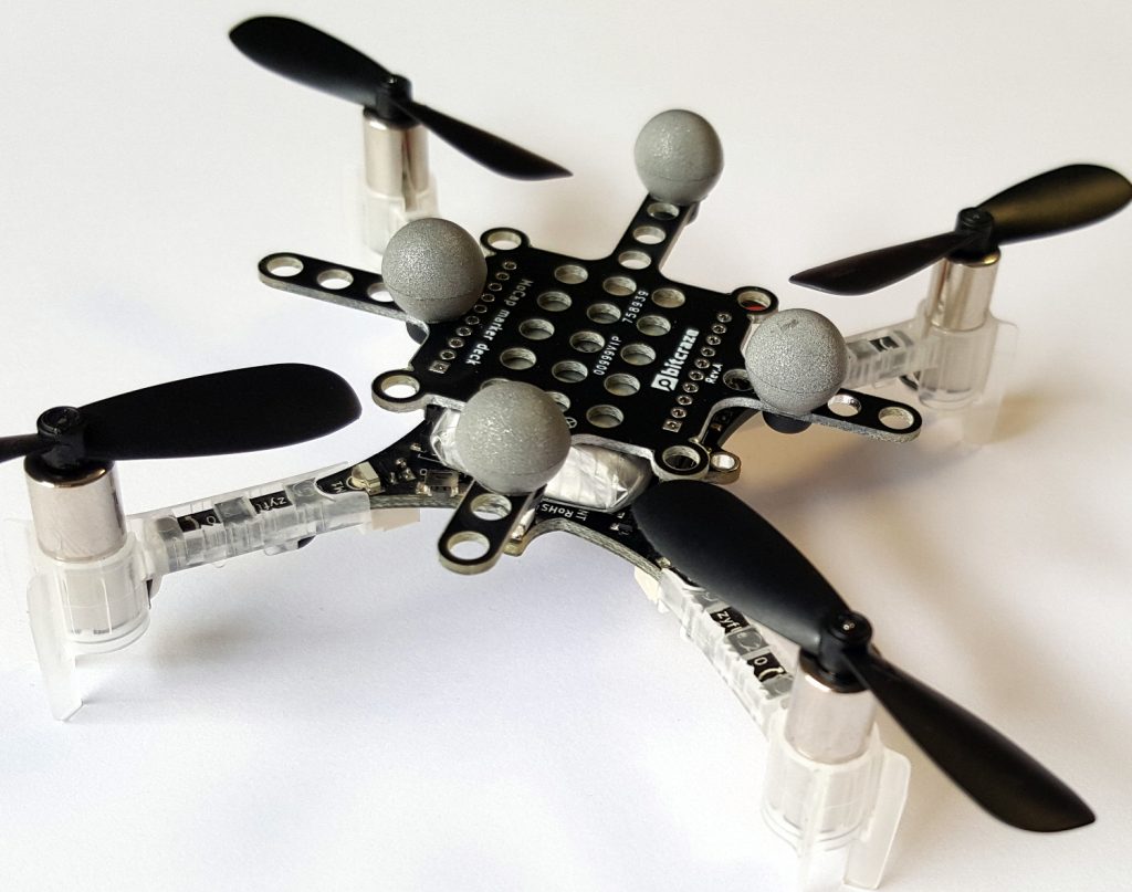
Passive markers
The most common marker type is the passive marker, that is reflective spheres that are attached to the robot. By using infrared flashes on the cameras, the visibility of the markers is maximized and it makes it easier for the system to detect and track them. We are selling the Motion capture marker deck to make it easy to attach markers to a Crazyflie.
To get the full pose (position, roll, pitch, yaw) of a robot, the markers must be placed in a configuration that makes it possible for the mocap system to identify the orientation. This means that there must be some asymmetry in the marker positions to understand what is front, back, up, down and so on.
With a swarm of Crazyflies, unique marker configurations makes it possible to distinguish one individual from another and track all drones simultaneously. With a larger number of robots it becomes cumbersome though to place markers in unique configurations, and one approach to solving this problem is to have known start positions for all individuals and keep track of their motions over time instead. This solution is used in the Crazyswarm for instance and all Crazyflies can use the same marker configuration in this setup. Another approach is to make it possible to distinguish one marker from another, enter the Active marker deck.
Active markers
It is possible to use infrared LEDs instead of the passive markers, this is called active markers. The LEDs are triggered by the flash from the cameras and they are easily detected as strong points of light. Since they are emitting light they can be detected further away from the camera than a passive marker and the smaller physical size also keeps them more separated when they are far away and only a few pixels are available to detect them in the camera.
Furthermore Qualisys has a technology that makes it possible to assign an id to each marker and that enables the tracking system to identify individual markers and thus uniquely identify individuals in a swarm. With different IDs on the markers, there is no need have asymmetrical configurations and the marker layout can be the same on all drones. It also reduces the risk of errors in the estimated pose, since there is more information available.
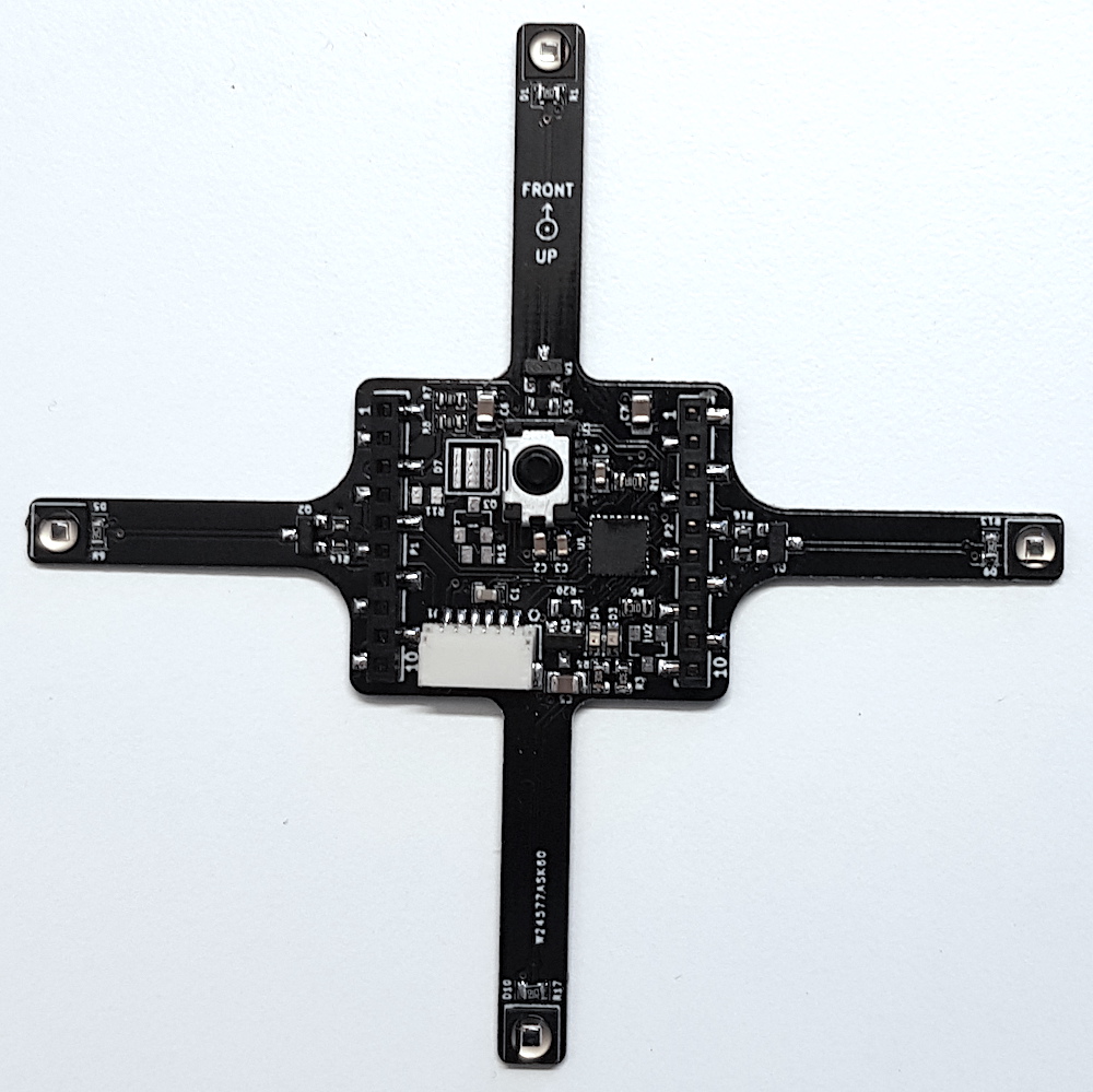
The deck
The Active marker deck is designed to go on top of the Crazyflie and has four arms with one LED each. The arms are as long as possible to maximize the signal/noise ratio in the cameras, while still short enough to be protected from crashes by the motors. There is a STM32 F0 on the deck that takes care of the LEDs and handling of IDs and the main Crazyflie CPU does not have to spend any time on this.
The status of the deck is that the hardware is fully functional (we might want to move something around before we produce it though) and that there is a basic implementation of the firmware. IDs are assigned to the markers using parameters in the standard parameter framework in the client or from a script.
We will start production of the deck in the near future and it will be available in the store this autumn. Qualisys added support for rigid bodies using active markers in V2019.3 of the QTM tracking software.
We attended the Innovation Week at Lund University on Thursday last week. Primarily we wanted to talk to students and possibly find future colleagues (yes, we are hiring) but it was also a good opportunity to get some demo time with the Lighthouse positioning system.
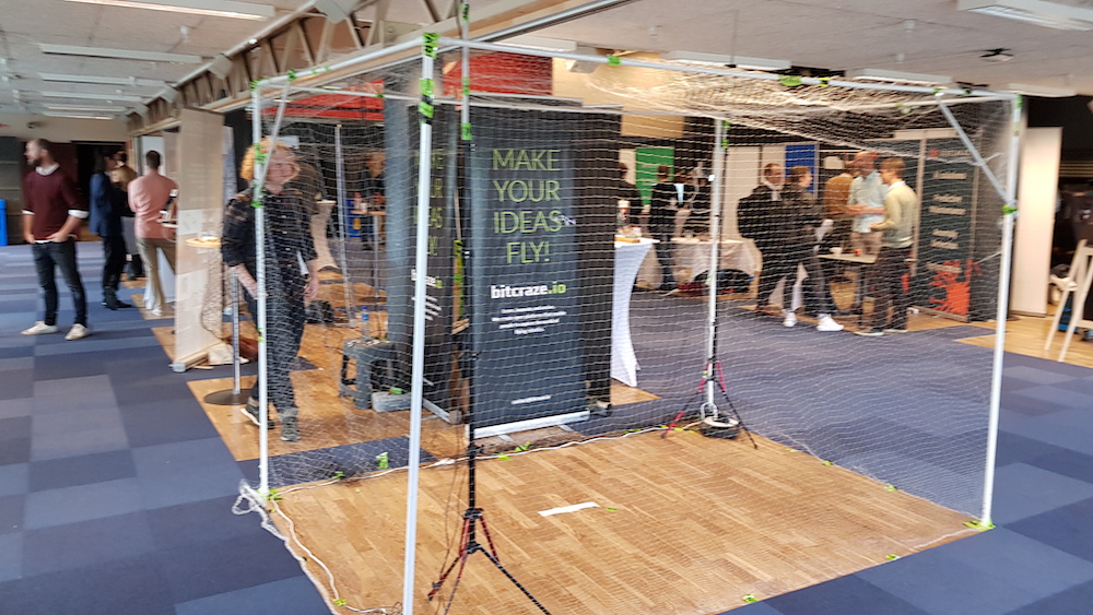
The demo setup. A bit blurry, sorry!
As mentioned in an earlier blog post, we are going to ICRA in May and we have started to think about what to demo. The main feature will of course be the Lighthouse deck. The setup at Innovation week also served the purpose of a first iteration for the ICRA setup.
We reused an old cage that we created for another fair a couple of years ago, built from a garden tent. It turned out to be fairly wobbly and a bit heavy (steel tubing) considering we will bring it in our luggage to Canada. We probably have to rethink the construction a bit and see if we can change to aluminium.
We put the Lighthouse base stations on tripods, which worked like a charm in our flight lab. We found that we had a lot of problems calibrating the system, not to mention flying the Crazyflie, at the Innovation week fair though. It turned out that the floor was not as stable as one might expect and that the tripods were swaying when people walked by. We solved the problem by adding a tube to the top of tripod that was pushed against the ceiling and thus minimizing the movement. Experience from the real world is always useful!
The general idea for the demo at ICRA is to automate as much as possible to give us more time with visitors. With the high precision of the Lighthouse system, it should be easy to land the Crazyflies on Qi chargers to avoid changing batteries. We hope to set up 6-8 Crazyflies where one is always flying while the others are charging, and have the possibility to temporarily fly more Crazyflies for small swarms. It is still just ideas and we will not see the end result until we are at ICRA, but it will be fun to build!
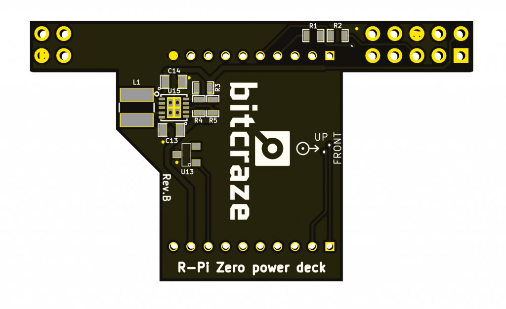
Ever since the Raspberry-pi zero was released we wanted to find-out what it would take to fly one with the Crazyflie 2.0. One immediate issue is the size and weight of the R-Pi-Zero. It is just a bit to big and heavy to make it work without modifying the Crazyflie 2.0. Also it requires 5V power which is something the Crazyflie 2.0 doesn’t provide if USB isn’t connected. Actually the R-Pi-Zero works well down to ~3.6V but this is still too high to reliably run directly from a single LiPo cell. So to begin with we created a Raspberry Pi Zero power deck. It is reusing the same step-up/step-down (STBB1) as used on the LED-ring to make things simple and the output is set to 3.8V. Other than that the UART and the I2C interfaced has been connected so that the raspberry pi zero could control the Crazyflie.
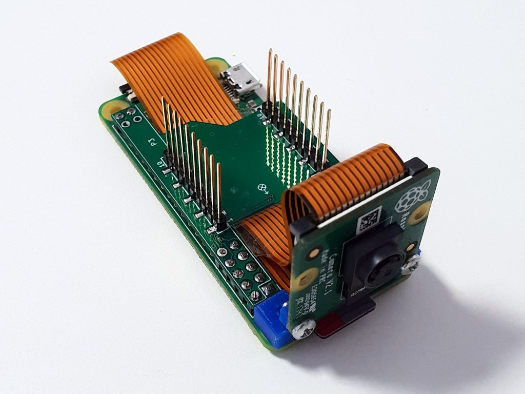
The raspberry pi zero would then be soldered to the deck with 0.1″ header pins. The result can be seen below and the power part works well. We chose to solder the deck header pins to the deck, instead of using the female deck connectors, to make it more sturdy. Another thing we did was fitting a Pi-camera using a 3D printed mounting bracket we designed. We think this is one of the interesting use cases, to run computer vision or maybe neural networks :-).
Well unfortunately this only solves the first part, powering the R-Pi-Zero from the Crazyflie 2.0. Next step will be to modify the Crazyflie 2.0 with bigger motors/props so that is can carry it for a decent time. So story to be continued…