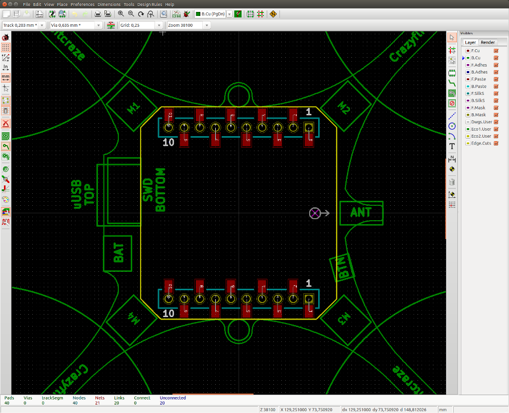
The production of the first Crazyflie 2.0 batch is still on track. Currently all the components are being purchased and when they are all in, the assembly will start. We are still busy preparing things for the production, but we have now slowly shifted over to software and firmware development. The last week has been spent implementing the bootloader and implementing our communication protocol (CRTP) over USB support.
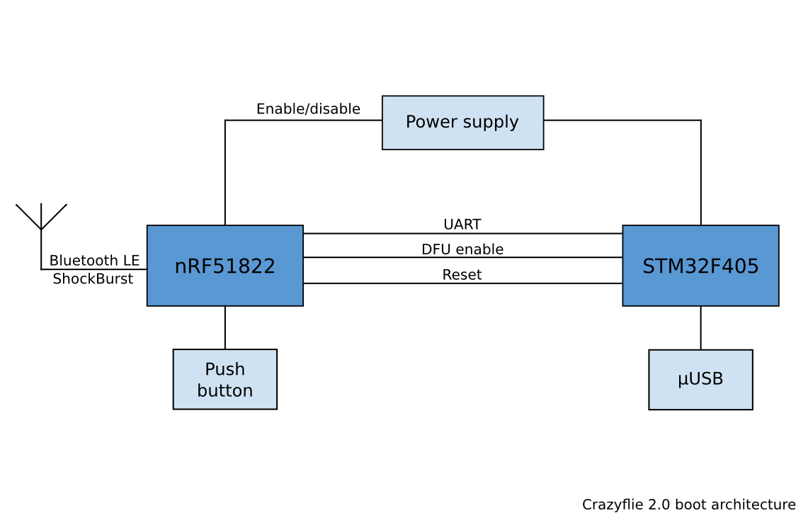
The bootloader has gone from a simple piece of firmware to something that’s more complex. For the Crazyflie 2.0 we have a dual-MCU architecture, which means that we have to flash two MCUs instead of one. Aside from that we now also support bootloading via Bluetooth LE as well as the enhanced shockburst protocol. Another fact that complicates things is that the nRF51 uses a closed binary for it’s Bluetooth LE support, which means we have to take special care when upgrading it. But the trickiest part of all this is to make it safe so that it’s always possible to rescue the system without needing a JTAG/SWD dongle if something goes wrong. It’s important to get it right, since the bootloader is flashed during production it can’t be updated at a later stage without using JTAG/SWD.
The Crazyflie 2.0 only has one button and it’s connected to the nRF51. Instead of directly switching on/off the power to the platform like on the Crazyflie 1.0, the button is now multi-functional. Pressing it will turn on/off the power and put the nRF51 to sleep, but holding it down when powering on the Crazyflie 2.0 will affect the start-up behavior. By holding it down 1.5 seconds the bootloader will launch and by holding it down 5s the STM32F4 will start in DFU mode (Device Firmware Upgrade). One of the reasons for designing in the DFU functionality was to use it as a last resort to rescue the system in case we couldn’t make the nRF51 bootloader secure. Another reason for it is that we always try to design in lots of possibilities, even if we can’t find a use for it we are hoping someone else will.
CRTP over USB is something that’s been on our TODO list for at least 2 years, but we have never gotten around to it. One idea we had was for building a bigger quadcopter using a Raspberry Pi and a Crazyflie connected to it via USB. The Crazyflie would still be used as the real-time control board, but would receive commands on the USB. This would allow the Crazyflie to become a quadcopter control board using our normal Python API for commands from Linux. This way we could for instance create a higher level autonomous system. But now we needed it for one of our test-rigs, so we had to sit down and get it done. For the implementation we use a raw USB device (i.e class 0) where we use the end-points to send CRTP packets back and forth from the PC. Since a CRTP packet is smaller than a USB packet, there’s no need for flow control or any extra protocols, we just receive new packets on the OUT requests and send a new packets back on the IN requests (if there’s any available). This fits nicely into the current architecture of the Crazyflie Python Lib and the firmware, but it still needs some cleaning up. Once everything is done it will be merged into the main firmware as well.