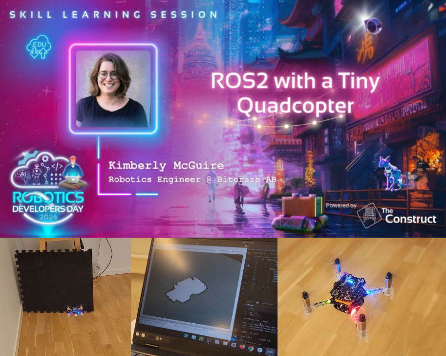
Welcome to the “The Beginner’s Guide to Drones” for programmers curious about exploring the world of unmanned aerial vehicles (UAVs). If you’re a coder from another field, this guide will walk you through the basics of drones, their components, and how to start programming them. Let’s dive in and see how your coding skills can take flight!
If you come from an engineering field, you might already know the basics of some of these topics, however you might still have use of the overview and can use the resources to get more specific knowledge.
The Robotics part
First and foremost, you’ll need some basic robotics skills.
We start of with the most basic question, “What is a Robot?”. A robot uses sensors to create an internal model of its environment, and actuators to act on/in its environment. The specifics of the internal model depend on the robot’s purpose, but a crucial component is understanding its location and orientation within that environment.
Linear algebra basics
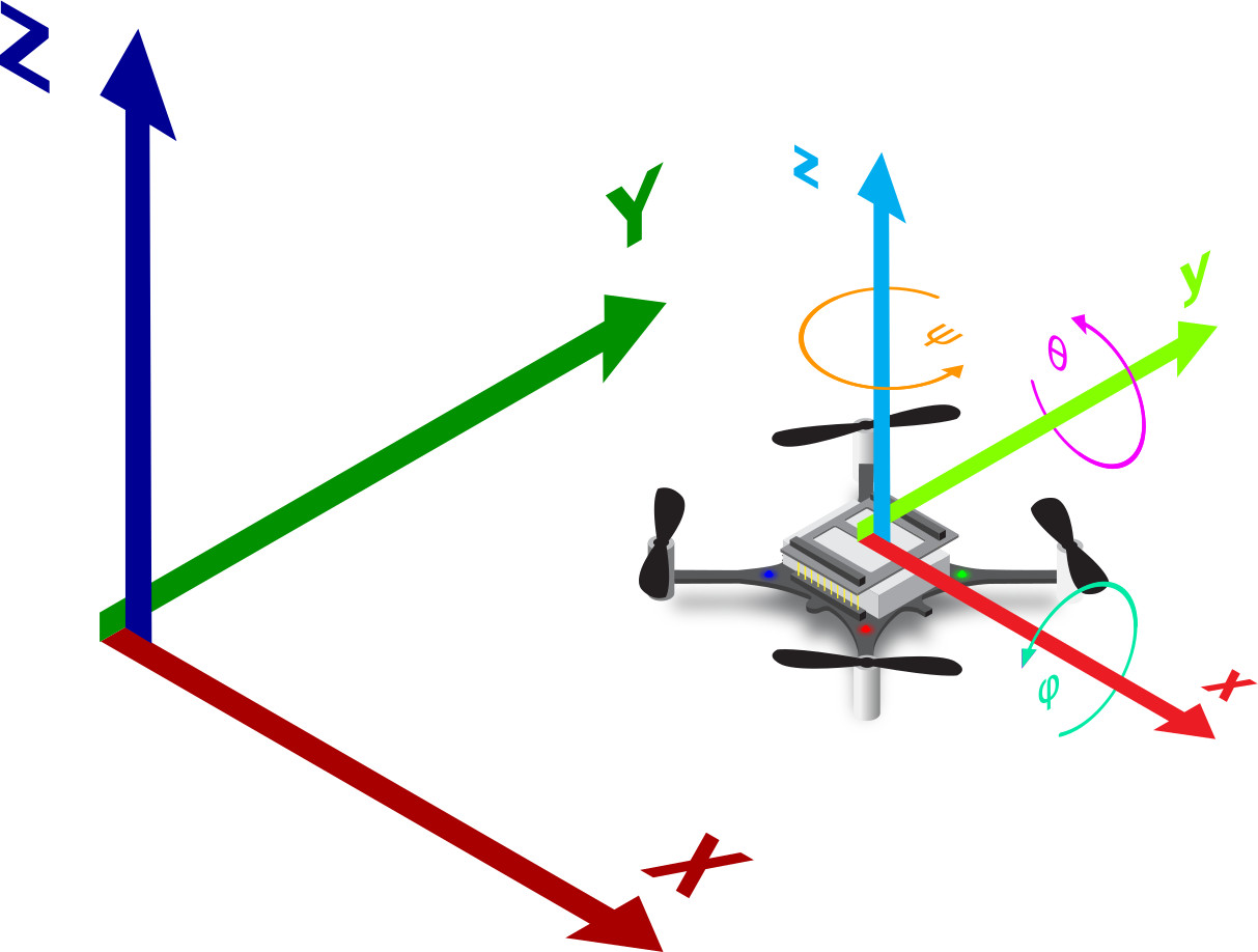
To understand how a quadcopter perceives its environment and its own position, you’ll need some basic skills in linear algebra, particularly in matrices, vectors, and frame rotation. These skills are essential for comprehending the mathematical principles behind quadcopter navigation.
To build an internal model of its own movement and orientation, an Inertial Measurement Unit (IMU) is used. An IMU consists of a gyroscope, an accelerometer, and sometimes a magnetometer. These sensors, when combined using sensor fusion techniques (See “Control Theroy” below), help determine the quadcopter’s angular velocity and linear acceleration. This data allows the drone to calculate its orientation and movement.
For a detailed understanding of these processes, please refer to the following resources:
Visual description of frame transformations;
https://www.youtube.com/watch?v=kYB8IZa5AuE
Basic coordinate transformations;
https://motion.cs.illinois.edu/RoboticSystems/CoordinateTransformations.htmlbasi
- Visual description of frame transformations: https://www.youtube.com/watch?v=kYB8IZa5AuE
- Basic coordinate transformations: https://motion.cs.illinois.edu/RoboticSystems/CoordinateTransformations.htmlbasi
Positioning techniques
The quadcopter can now determine its relationship to its starting position and the gravitational field. However, relying solely on an IMU tends to cause drift over time. Imagine trying to stand on one leg with your eyes closed—eventually, you’ll lose balance.
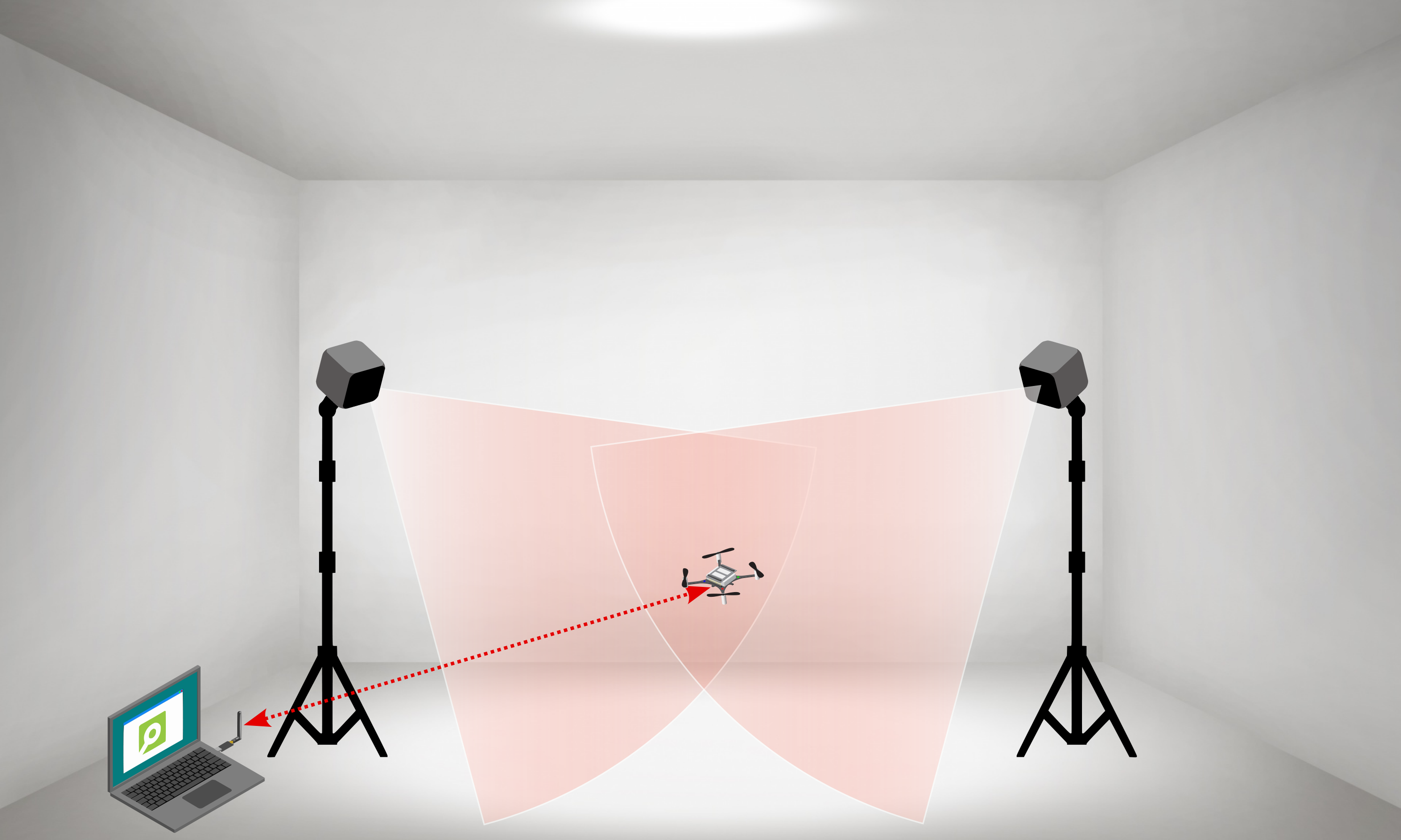
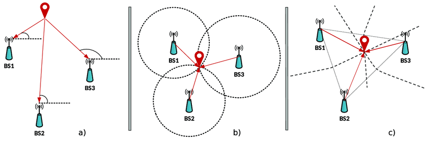
For improved stability, a drone often needs additional sensors, such as a camera, to help stabilize its position. Other sensor systems can also be used to determine relative or absolute position. While an IMU can sense changes in position relative to a starting point, an external positioning system is necessary for stability and obtaining absolute positions. This system acts as a reference frame for the drone.
Drones flying outdoors typically use GPS combined with RTCM, since it is available almost anywhere, ease to use, and has centimeter-level accuracy.
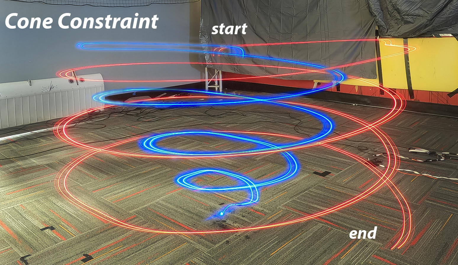
For indoor use, as with Crazyflies, the default used positioning system is motion-capture system but there are others as well. This area is at the cutting edge of science, with new technologies emerging constantly. However, many effective systems are available, though they may have constraints regarding power efficiency, flight area size, update speed, or precision.
Control theory
Now that drone can understand its position and orientation in space, the next step is figuring out how to move within this space. Moving from point A to point B involves setting a “setpoint” and then determining how to use the drone’s actuators to reach this setpoint most efficiently. This is where control theory comes into play.
Drones generally use some sort of feedback control system, which in its most basic form looks something like this:

In this system, the error (the difference between the current position and the setpoint) is fed back into the system to ensure the drone moves in a way that minimizes the error over time.
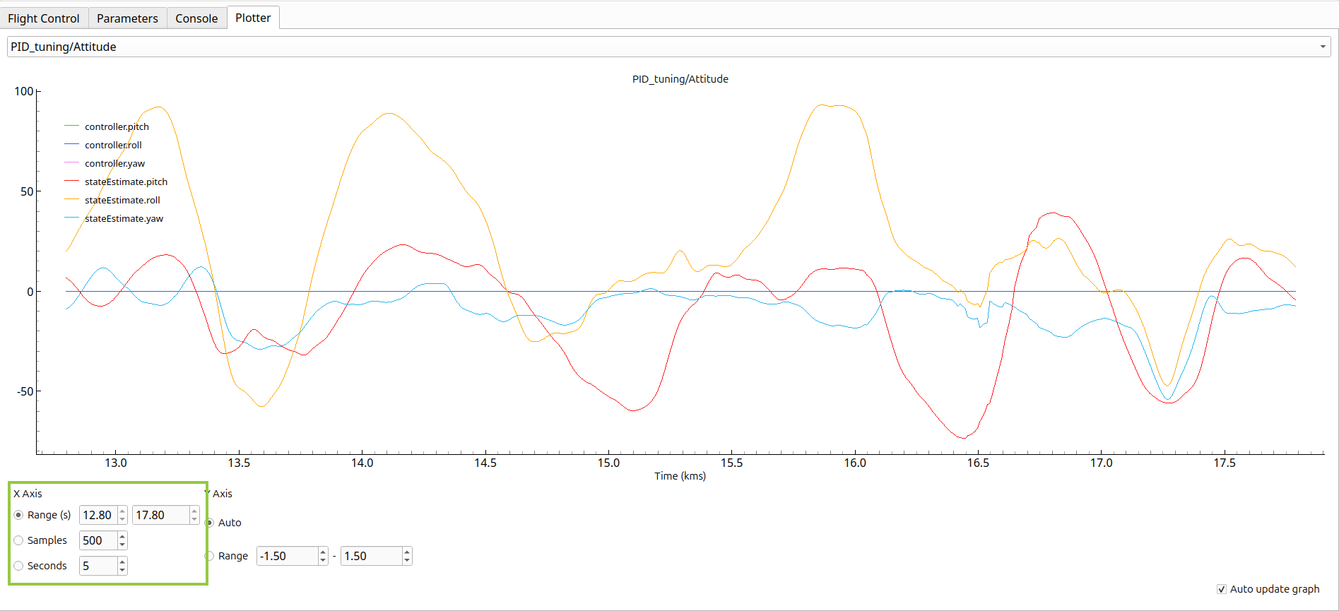
Various algorithms can calculate the best actuator output based on the error and current state. One of the most fundamental algorithms is the PID controller, which works well for linear systems. Understanding PID controllers requires some basic calculus, but the concept is straightforward. Here are some resources for simple explanations:
- PID controller overview: https://www.ni.com/en/shop/labview/pid-theory-explained.html
For IMUs, there is a particularly useful filter to know about, given its widespread use. The accelerometer and gyroscope each have their own profiles of noise and drift. The accelerometer is sensitive to short-term noise, while the gyroscope drifts slowly over time. To mitigate these issues, a combination of both measurements is often used. The complementary filter is ideal for this situation, leveraging the strengths of both sensors to correct the measurements effectively.
More information on how to use the complementary filter for IMUs can be found here:
https://www.hackster.io/hibit/complementary-filter-and-relative-orientation-with-mpu9250-d4f79d
For more complex scenarios, advanced controllers like Kalman filters and others can be used. It’s also possible to combine multiple controllers to achieve better performance.
Basic overview of feedback control systems;
https://control.com/textbook/closed-loop-control/basic-feedback-control-principles/
The flying part
Now lets get into the exciting part. FLYING!!!
Actuators
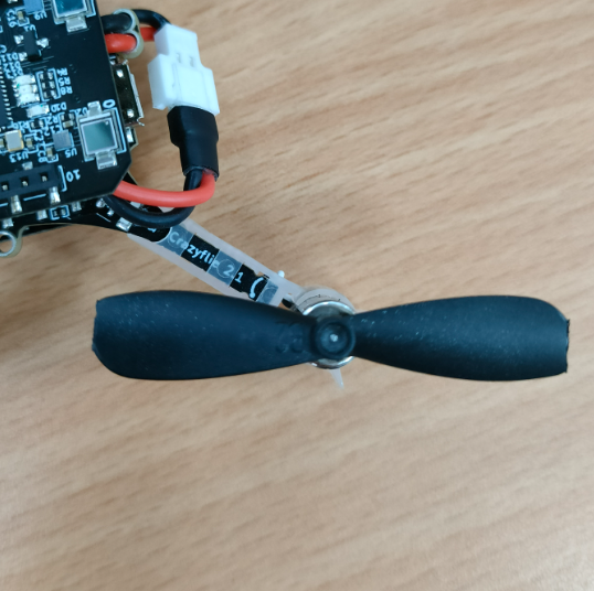
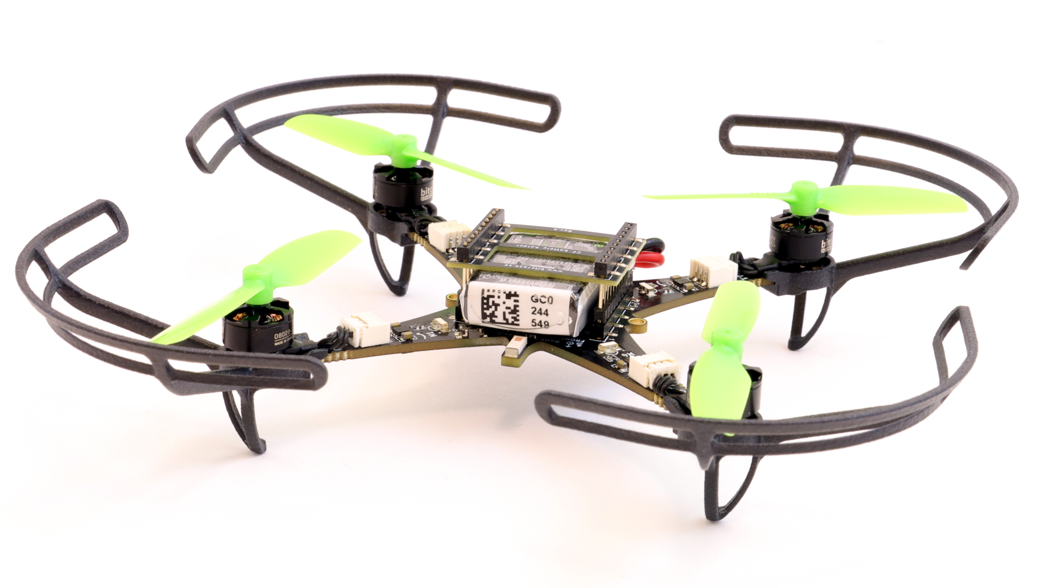
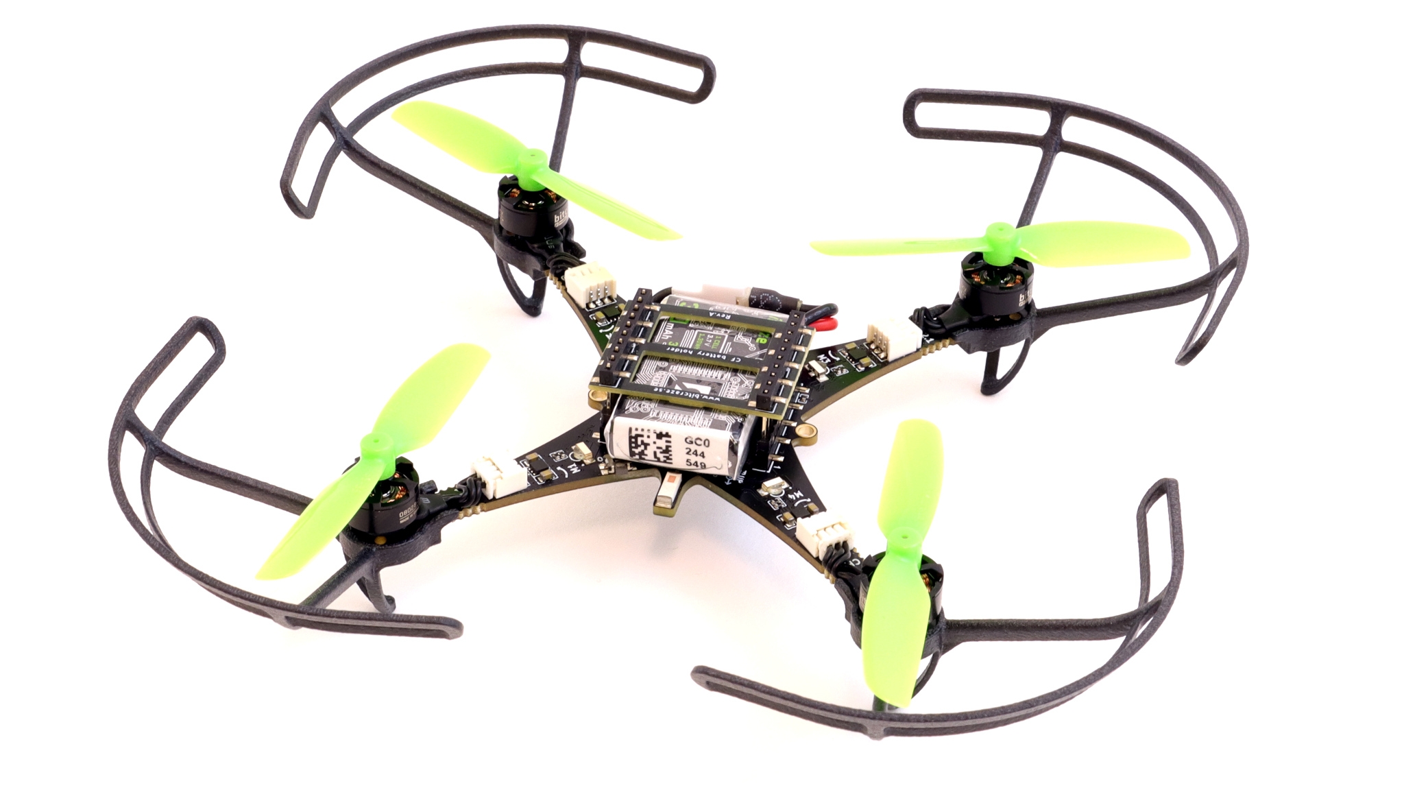
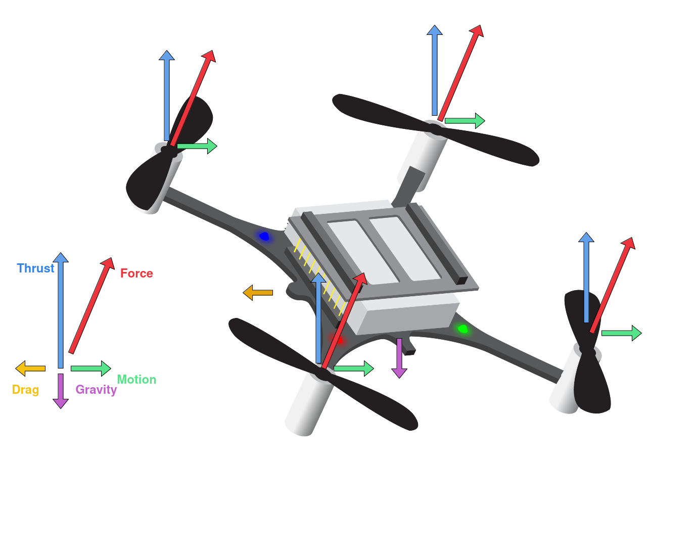
Drone actuators, primarily consisting of motors and propellers, are critical for controlling a drone’s movement and stability. The motors and propellers are typically called the “drive train” or “power train”.
The motors used on drones are usually brushed or brushless DC motors. Propellers are attached to the motors and generate lift by pushing air downwards. The size, shape, and pitch of the propellers affect the drone’s performance, including speed, lift, and maneuverability. Together, the precise control of motors and propellers enables a drone to perform complex maneuvers, maintain stability, and achieve efficient flight.
This is an almost all you need guide to get an overview of drone flight dynamics
https://dronstechnology.com/the-physics-of-drone-flight-lift-thrust-drag-and-weight/
Stock information
As of now the Crazyflie 2.1 is out of stock, unfortunately. They’re expected back in stock around August 20th – 4 weeks from now. You can sign up in our shop to be notified as soon as they arrive!
https://store.bitcraze.io/collections/kits/products/crazyflie-2-1?variant=19575412719703