This week’s guest blogpost is from Xinyu Cai from the research group of ShaoHui Foong, located in the Engineering Product Development Faculty from Singapore University of Technology and Design. Please check out their youtube channel. Enjoy!
Unmanned Aerial Vehicles (UAVs) have garnered much attention from both researchers and engineers in recent decades. Aerial robots in general are classified into mainly three categories: fixed wings, rotary wings and flapping wings.
Fixed wings are one of the most common aerial vehicles as it has relatively higher power efficiency and payload capacity than other types, thanks to their big and highly customizable wing. But this also leads to a bigger footprint and usually the lack of ability for Vertical Taking Off and Landing (VTOL). Rotary wings generally include helicopter and multirotors (such as quadrotors), and they have recently become increasingly popular in our daily lives. Easily achieving great performance in attitude and position control, rotary wings are widely applied in many fields. Flapping wing robots take inspirations from small flapping insects (such as Harvard Robobee) or birds (Purdue Hummingbird Robot).
Monocopters are largely inspired from the falling motion of maple seeds, and they are relatively much simpler to build as compared to its counterparts. They can keep a relative smaller footprint and achieve decent control performance although they are highly underactuated. The Single Actuator Monocopter (SAM) has the ability to VTOL, perform 3D trajectory tracking as well as maintain high hovering efficiency. With those advantages, rapid developments have been made in recent years such as the Foldable Single Actuator Monocopter (F-SAM) and Modular Single Actuator Monocopter (M-SAM) from Engineering Product Development (EPD) of Singapore University of Technology and Design (SUTD).
Taking inspiration from nature – Samara inspired monocopter
A descending samara or maple seed, is able to passively enter auto-rotation motion and stabilize its flight attitude, helping to slow down its descent speed and travel further for better survival of the species. This natural behavior attracts interests from scientists and researchers. With previous studies, we learnt that this passive attitude stability is mainly guaranteed by mass distribution (Center of Mass) and wing geometry (Center of Pressure) as well as the rotation motion.
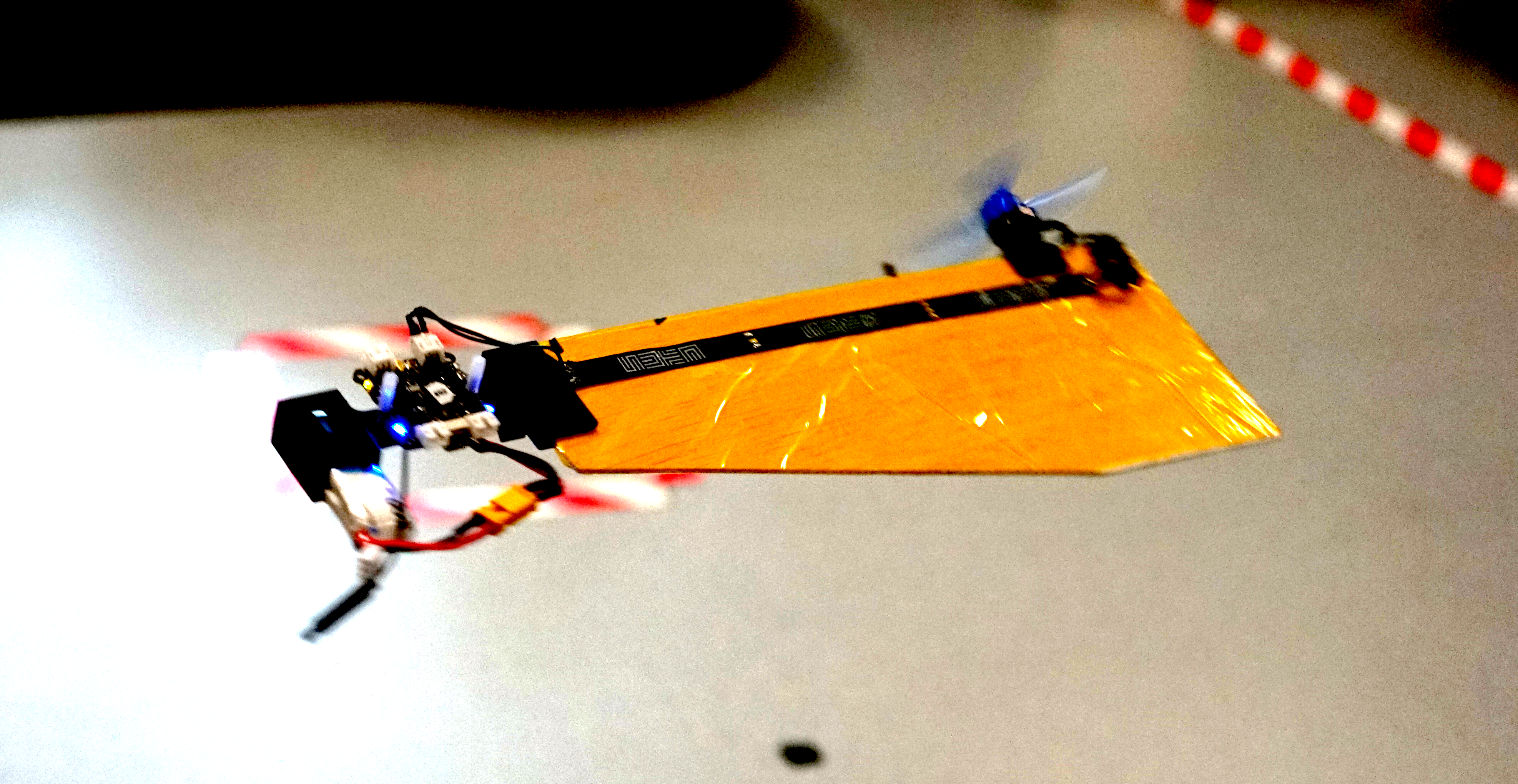
The SAM is designed to be very close in its mechanical make-up to its natural sibling, having a large single wing structure and a smaller, denser ‘seed’ structure. A single motor with propeller is installed on the leading edge, parallel to the wing surface. Comparing with flight dynamics of the original maple seed, SAM has extra torques and force caused by the spinning propeller, including a reaction torque and thrust directly from propeller, as well as an extra torque caused by precession motion. As a result, the balance of the combined forces and torques allows SAM to enter a new equilibrium condition while still retaining the passive attitude stability.
Development of monocopters
The research on monocopters can be traced back to a long time ago. Here are some examples of different types of air frame to roughly introduce their developments. An air-frame called Robotic Samara [1] was created in 2010, which has a motor to provide rotational force, a servo to control collective pitch of the wing, a winged body fabricated by carbon fiber, and a lipo battery. In the following year, Samarai MAV [2] was developed by following the mass distribution of a natural maple seed. To achieve the control, a servo is equipped to regulate the wing flap. In 2020, a single actuator monocopter was introduced with a simplified air-frame [3]. The main structure is made by laminated balsa wood while the trailing edge of the wing is made by foam for better mass distribution. By making use of the passive attitude stability, only one actuator is required to control the position in 3D space. Based on which, F-SAM [4] and M-SAM [5] were developed in 2021 and 2022 respectively.
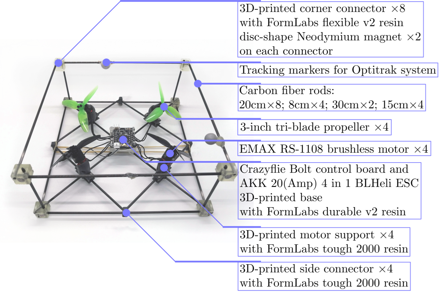
A Modular SAM (M-SAM) with Crazyflie Bolt
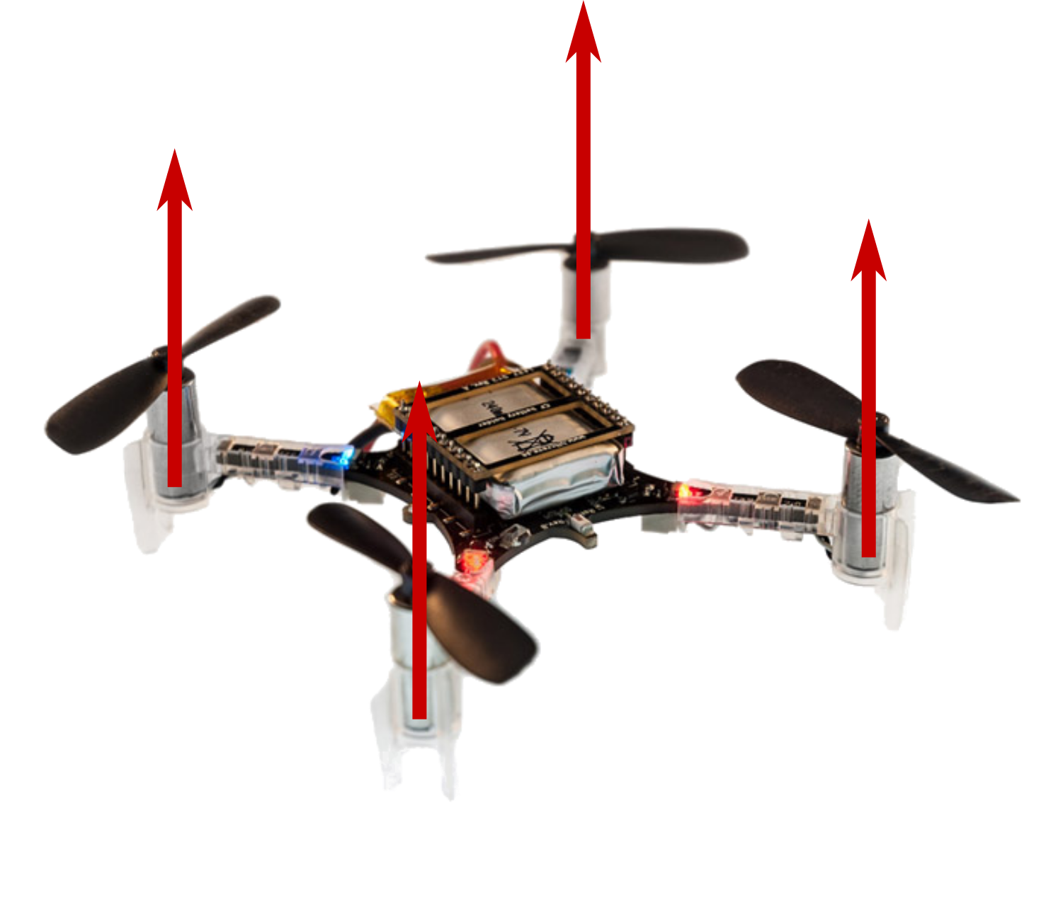
Thanks to its easy implementation and reliable performance, we use the Crazyflie Bolt as the flight controller for M-SAM. Like other robotic systems, the ground station is integrated with motion capture system (position and attitude feedback for both control and ground truth) and a joystick (control reference directly generated by user) is responsible for sending filtered state feedbacks and control references or control signal directly to flight controller. This is realized by employing the Crazyradio PA under the Crazyflie-lib-python environment. Simple modifications from the original firmware were made to map from the control reference to motor command (a customized flight controller).
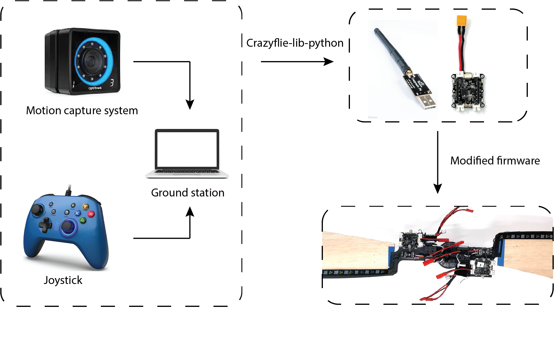
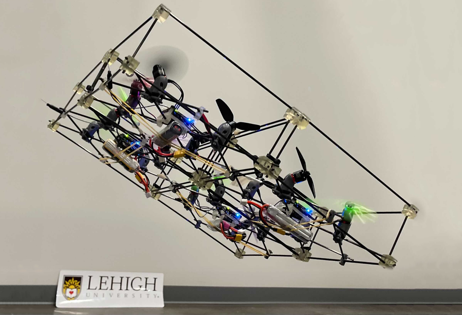
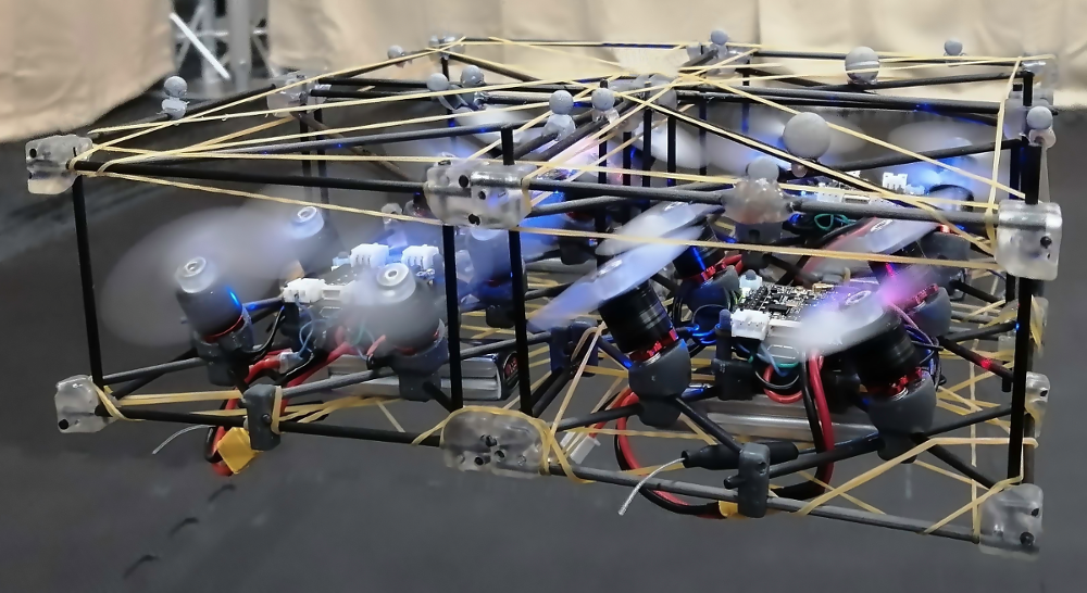
Another advantage of using Crazyflie Bolt in M-SAM project is its open source swarm library. Under the swarm environment, SAMs can fly in both singular and cooperative configurations. With simple human assistance, two SAMs can be assembled into cooperative configuration by making use of a pair of magnetic connectors. The mid-air separation from cooperative configuration to singular configuration is passively triggered by increasing the rotating speed until the centrifugal force overcomes the magnetic force.
Potential applications
What kinds of applications can be achieved with the monocopter aerial robotic platform? On the one hand, many applications are limited by the nature of self-rotation motion. On the other hand, the passive rotating body also offers advantages in some special scenarios. For example, SAM is an ideal platform for LIDAR application, which usually requires the rotating motion to sense the environment around. Besides, thanks to simple mechanical design and cheap manufacturing cost, SAM can be designed for one time use such as light weight air deployment or unknown, dangerous environments.
Reference
- [1] Ulrich, Evan R., Darryll J. Pines, and J. Sean Humbert. “From falling to flying: the path to powered flight of a robotic samara nano air vehicle.” Bioinspiration & biomimetics 5, no. 4 (2010): 045009.
- [2] Fregene, Kingsley, David Sharp, Cortney Bolden, Jennifer King, Craig Stoneking, and Steve Jameson. “Autonomous guidance and control of a biomimetic single-wing MAV.” In AUVSI Unmanned Systems Conference, pp. 1-12. Arlington, VA: Assoc. for Unmanned Vehicle Systems International, 2011.
- [3] Win, Luke Soe Thura, Shane Kyi Hla Win, Danial Sufiyan, Gim Song Soh, and Shaohui Foong. “Achieving efficient controlled flight with a single actuator.” In 2020 IEEE/ASME International Conference on Advanced Intelligent Mechatronics (AIM), pp. 1625-1631. IEEE, 2020.
- [4] Win, Shane Kyi Hla, Luke Soe Thura Win, Danial Sufiyan, and Shaohui Foong. “Design and control of the first foldable single-actuator rotary wing micro aerial vehicle.” Bioinspiration & Biomimetics 16, no. 6 (2021): 066019.
- [5] X. Cai, S. K. H. Win, L. S. T. Win, D. Sufiyan and S. Foong, “Cooperative Modular Single Actuator Monocopters Capable of Controlled Passive Separation,” 2022 International Conference on Robotics and Automation (ICRA), 2022, pp. 1989-1995, doi: 10.1109/ICRA46639.2022.9812182.
- [6] Bai, Songnan, Qingning He, and Pakpong Chirarattananon. “A bioinspired revolving-wing drone with passive attitude stability and efficient hovering flight.” Science Robotics 7, no. 66 (2022): eabg5913.