Today, we welcome Dimitrios Chaikalis from New York University to talk about their project of cooperative flight. Enjoy!
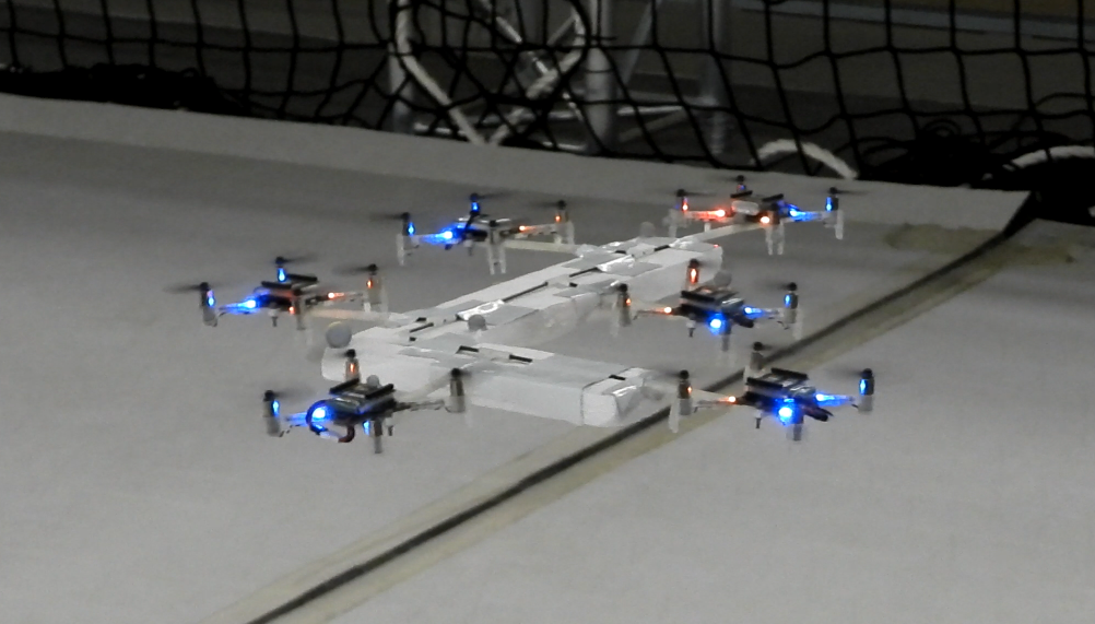
For our work in cooperative flight, we developed controllers for many tightly coupled drones to fly as a unit. The idea is that, either in a centralized or decentralized manner, it should be possible to treat drones as thrust force and yaw moment modules, in order to allow many small drones to carry objects too heavy for a single one to lift.
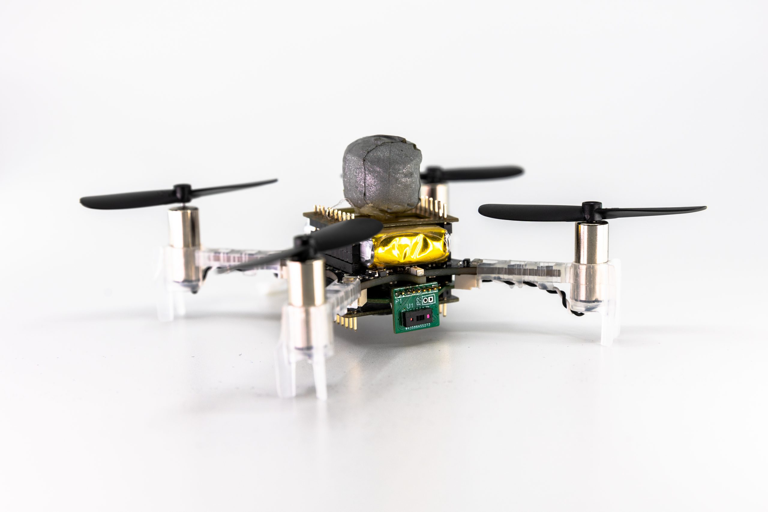
It quickly turned out that the Crazyflies, with their small size, open-source firmware, ROS compatibility, and, as we happily found out after hours upon hours of crashes, amazing durability, would be the perfect platform to test our controllers.
We designed and 3D-printed very lightweight, hollow connecting rods that could latch onto Crazyflies on one side, along with a number of lightweight polygons such as squares and hexagons with housings for the other side of the rods on all their faces. This allowed us to seamlessly change between geometric configurations and test our controllers.
We first tested with some symmetric triangle and quad formations.
The above is probably literally the first time our cooperative configuration achieved full position control
The tests on quad-copter configurations started as we transitioned to fully modular designs
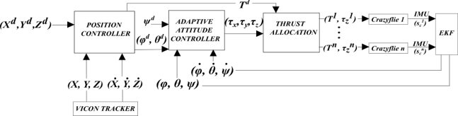
Eventually, to make the controller generic, we developed a simple script that could deduce with some accuracy the placement of drones given a small lexicographic description submitted by the tester as a string, essentially denoting a sequence of rods and polygons utilized in the current configuration. Of course, some parameters such as rod lengths, or additional weights that we added to the system (such as a piece of foam attached to the structure), could not be known in advance, but the adaptive controller design ensured that the overall system could still achieve stable flight.
Strangely, the L shape has become a sort of ‘staple’ configuration in cooperative load transportation
We also proved that with more than 3 drones in a configuration, we could optimize the thrusts of the agents such that additional performance criteria could be met. For example, in an asymmetric configuration of 5 drones, one of them had a significantly more depleted battery. Crazyflies provide real-time battery voltage feedback, so we were able to use that in an optimization node running in Matlab on a ground computer, choosing thrust levels such that the depleted agent could be utilized less. This was a significant help, because in many of those experiments, the Crazyflies had to operate at more than 80% of their thrust capacity, so battery life optimization was of the essence.
We used ROS for all the code written for the above implementations, using the Crazyflie-ROS package in order to get battery and IMU readings from all drones and provide thrust and roll, pitch, and yaw rate commands at up to 100Hz.
In case you want to build on our work, you can cite the above paper as such:
D. Chaikalis, N. Evangeliou, A. Tzes, F. Khorrami, ‘Modular Multi-Copter Structure Control for Cooperative Aerial Cargo Transportation‘, Journal of Intelligent & Robotic Systems, 108(2), 31.
Today, Vivek Adajania from Learning Systems and Robotics lab write about a project for a safe motion planning of Crazyflie swarm that was published at ICRA 2023. Enjoy!
Motivation
Quadrotor swarms offer significant potential in applications like search and rescue, environmental mapping, and payload transport due to their flexibility and robustness compared to single quadrotors. The core challenge in these applications is collision-free and kinematically feasible trajectory planning. As the quadrotors share space, they must safely manoeuvre around each other and avoid collisions with static obstacles. Existing solutions [1] [2], while effective for generating collision-free trajectories, often struggle in densely cluttered scenarios due to simplifying approximations.
Background
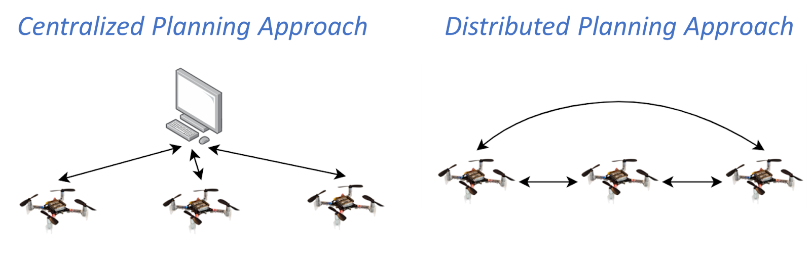
There are two literature groups in the domain of optimization-based quadrotor swarm motion planning: centralized and distributed approaches. In a centralized setup, a central computer solves a joint optimization problem that computes trajectories for all quadrotors at once. These approaches have broad solution space but quickly become computationally intractable as the number of quadrotors increases. On the other hand, the distributed approach involves each quadrotor independently solving its optimization problem and incorporating trajectories shared by the neighbouring quadrotors. This strategy offers improved scalability, yet existing distributed approaches struggle in cluttered environments.
Fig. Centralized and distributed planning approach to quadrotor swarm motion planning. The arrows indicate the flow of communication.
In this work, we adopt a distributed planning strategy. The independent optimization problem that needs to be solved by each of the quadrotors in the distributed setup is a non-convex quadratically constrained quadratic program (QCQP). This nature of the problem stems from non-convex and quadratic collision avoidance constraints and kinematic constraints.
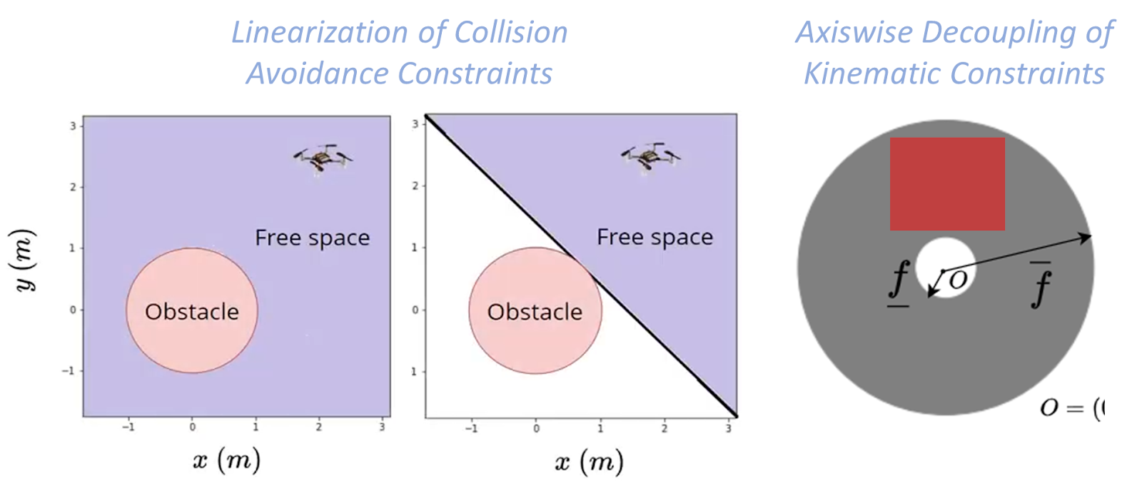
Existing distributed approaches rely on sequential convex programming (SCP) that performs conservative approximations to obtain a quadratic program (QP). First, linearization of the collision avoidance constraints to obtain affine hyperplane constraints. Second, axis-wise decoupling of the kinematic constraints to obtain affine box constraints. We obtain a QP but with small feasible sets.
Fig. Conservative approximations made by Sequential Convex Programming (SCP) based approaches.
Proposed Approach
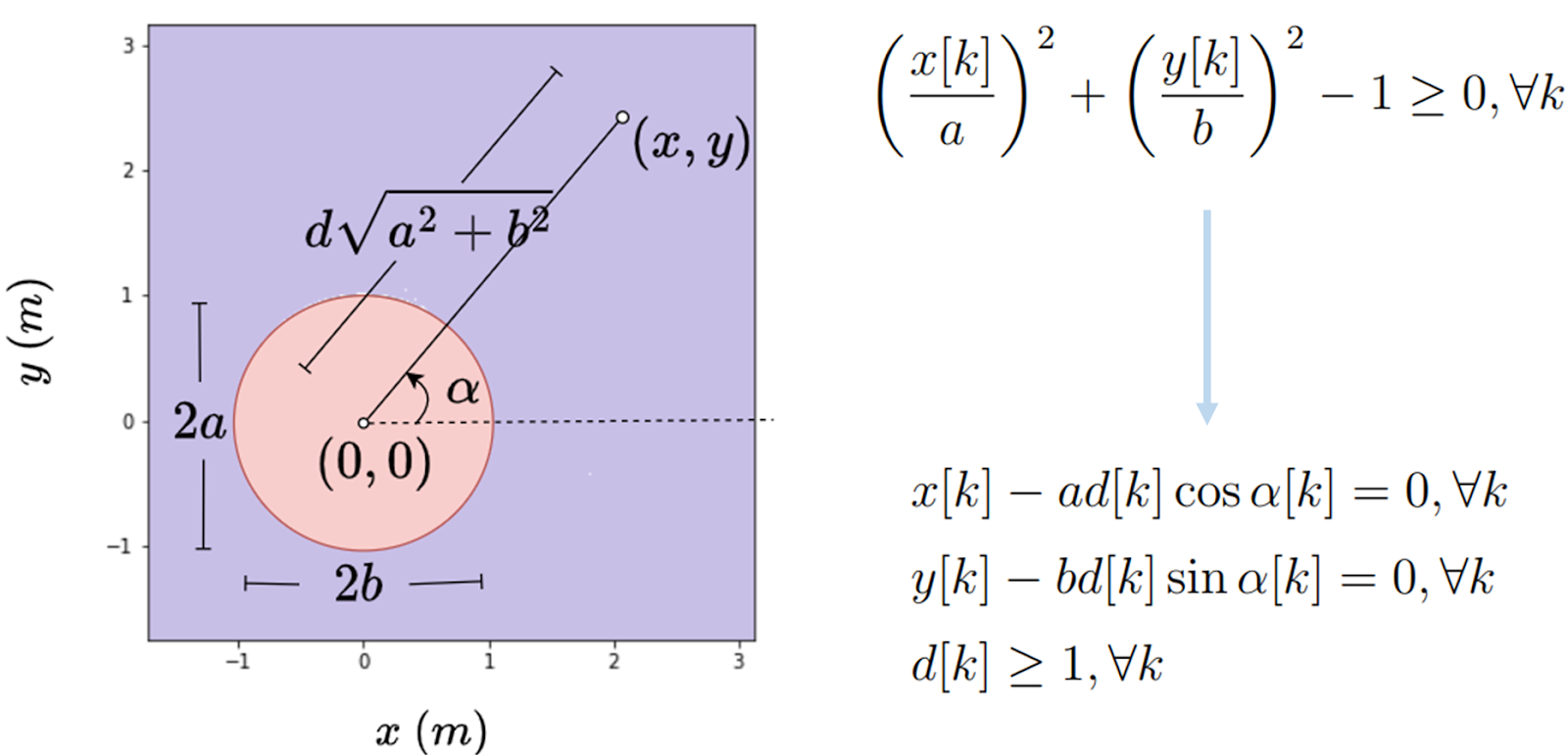
In contrast, our proposed approach obtains a QP without relying on the previously mentioned approximations. The first ingredient is the polar reformulation of collision avoidance and kinematic constraints. An example of the 2D polar reformulation of collision avoidance constraints is shown below:
Fig. Example illustration of polar reformulation of 2D collision avoidance constraints.
The second ingredient is to relax the reformulated constraints as l-2 penalties into the cost function and apply Alternating Minimization. Alternating Minimization results in subproblems that are convex QPs, and some have closed-form solutions, thus obtaining a QP form without relying on linearization; further details can be found in our paper [3]. We can also use and reformulate alternative collision avoidance constraints, barrier function (BF) constraints
where hij is the Euclidean distance between quadrotor i and quadrotor j, and the parameter γ controls how fast the quadrotor i is allowed to approach the boundary of quadrotor j.
Results
We experimentally demonstrate our approach on a 12 Crazyflie 2.0 swarm testbed in challenging scenes: obstacle-free, obstacle-rich, shared workspace with a human. The experimental video is provided below:
In the simulation, we compare our approach against two SCP approaches: SCP (Continuous) [2] enforces constraints across the entire horizon, while SCP (On-demand) [1] enforces only on the first predicted collision. Our (Axiswise) includes box kinematic constraints, while Our (Quadratic) preserves the original quadratic constraints.
From our simulation results, we see that SCP (On-demand) has a lower compute time than SCP (Continuous), as SCP (On-demand) enforces fewer constraints. But, this compute time trend comes at the expense of success rate. On the contrary, our approaches achieve a high success rate with low compute times. Ours (Quadratic) has a slightly higher success rate than Ours (Axiswise) as it has access to large kinematic bounds.
Fig. Simulation results from 100 start-goal configurations with swarm sizes ranging from 10 to 50 in a cluttered environment with 16 cylindrical static obstacles.
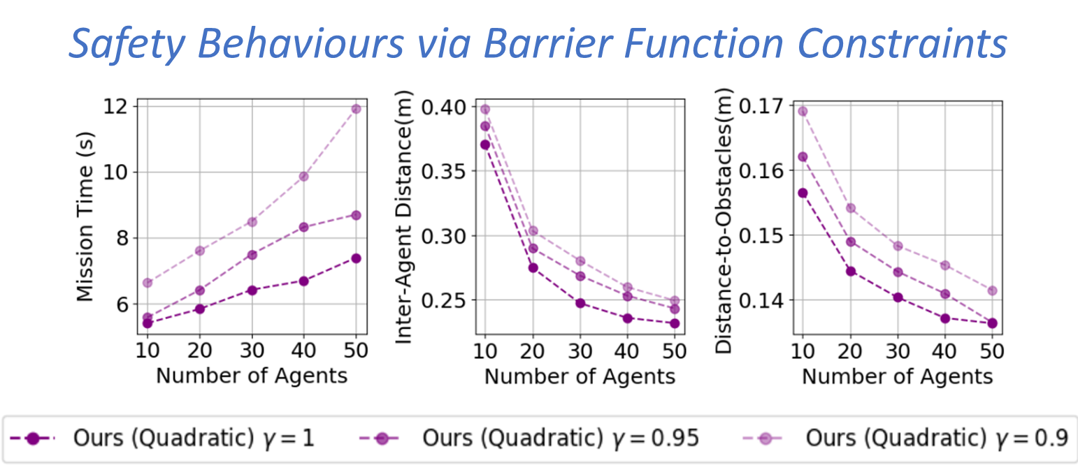
Fig. Simulation results from 100 start-goal configurations with swarm sizes ranging from 10 to 50 and three different γvalues in a cluttered environment with 16 cylindrical static obstacles.
On average, our approaches achieved a 72% success rate improvement, a 36% reduction in mission time, and 42x faster per-agent computation time—our approach trades-off mission time with inter-agent clearance and distance to obstacles via BF constraints.
Outlook
In this work, we presented an online and scalable trajectory planning algorithm for quadrotor swarms in cluttered environments that do not rely on the linearization of collision avoidance constraints and axis-wise decoupling of kinematic constraints. We do so by reformulating the quadratic constraints to a polar form and applying alternating minimization to the resulting problem. Consequently, our planner achieves high scalability and low computation times than existing approaches. We also show that we can reformulate barrier function constraints to introduce safety behaviours in the swarm. One of the future works is to extend the approach to navigate the swarm in a complex 3D environment.
References
[1] Luis, Carlos E., Marijan Vukosavljev, and Angela P. Schoellig. “Online trajectory generation with distributed model predictive control for multi-robot motion planning.” IEEE Robotics and Automation Letters 5.2 (2020): 604-611.
[2] E. Soria, F. Schiano and D. Floreano, “Distributed Predictive Drone Swarms in Cluttered Environments,” in IEEE Robotics and Automation Letters, vol. 7, no. 1, pp. 73-80, Jan. 2022, doi: 10.1109/LRA.2021.3118091.
[3] V. K. Adajania, S. Zhou, A. K. Singh and A. P. Schoellig, “AMSwarm: An Alternating Minimization Approach for Safe Motion Planning of Quadrotor Swarms in Cluttered Environments,” 2023 IEEE International Conference on Robotics and Automation (ICRA), London, United Kingdom, 2023, pp. 1421-1427, doi: 10.1109/ICRA48891.2023.10161063.
The authors are with the Learning Systems and Robotics Lab at the University of Toronto and the Technical University of Munich. The authors are also affiliated with the Vector Institute for Artificial Intelligence and the University of Toronto Robotics Institute (RI) in Canada and the Munich Institute of Robotics and Machine Intelligence (MIRMI) in Germany.
Feel free to contact us with any questions or ideas: vivek.adajania@robotics.utias.utoronto.ca. Please cite this as:
@INPROCEEDINGS{
adajania2023amswarm,
author={Adajania, Vivek K. and Zhou, Siqi and Singh, Arun Kumar and Schoellig, Angela P.},
booktitle={2023 IEEE International Conference on Robotics and Automation (ICRA)},
title={AMSwarm: An Alternating Minimization Approach for Safe Motion Planning of Quadrotor Swarms in Cluttered Environments},
year={2023},
pages={1421-1427},
doi={10.1109/ICRA48891.2023.10161063}
}
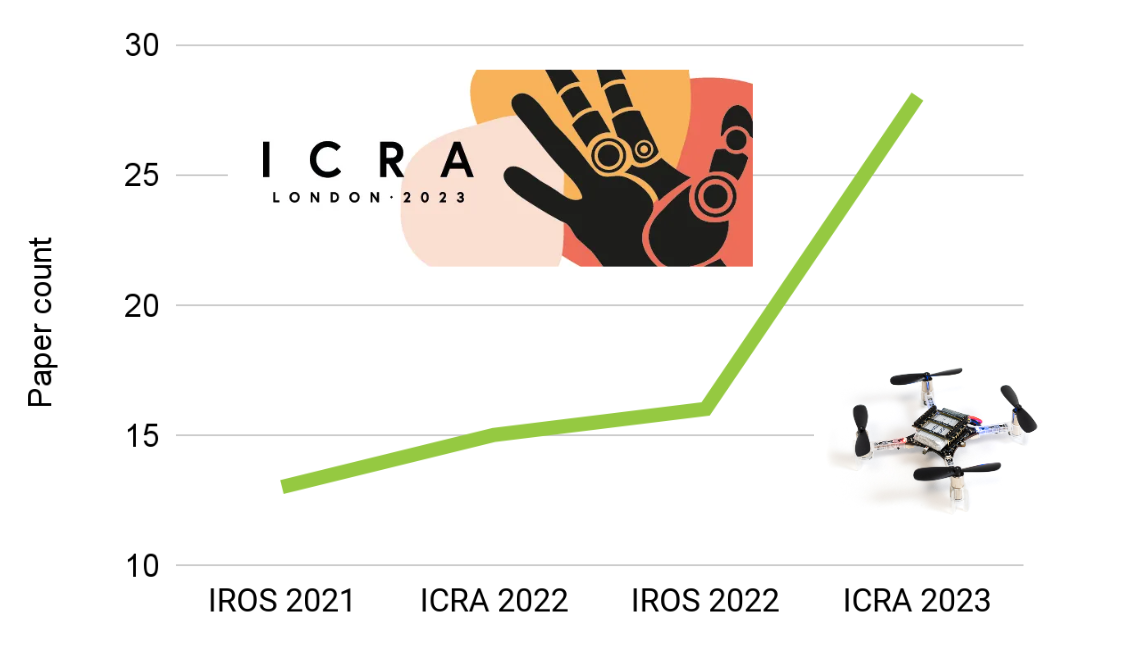
As you may have noticed from the recent blog posts, we were very excited about ICRA London 2023! And it seems that we had every right to be, as this conference had the highest number of Crazyflie related papers compared to all the previous robotics conferences! In the past, the conferences typically had between 13-16 papers, but this time… BOOM! 28 papers! In this blog post, we will provide a list of these papers and give a general evaluation of the topics and themes covered so far.
So here some stats:
ICRA had 1655 papers accepted (43 % acceptance rate)
28 Crazyflie papers (25 proceedings, 1 RA-L, 1RO-L, 1 late breaking result postor)
Haven’t included the workshop papers this time (no time)
The major topics we discovered were swarm coordination, safe trajectory planning, efficient autonomy, and onboard processing
Additionally, we came across a few notable posters, including one about a grappling hook for the Crazyflie [26], a human suit that allows for drone control [5], the Bolt made into a monocopter with a Jetson companion [16], and a flexible fixed-wing platform driven by a barebone Crazyflie [1]. We also observed a growing interest in aerial robotics with approximately 10% of all sessions dedicated to UAVs. Interestingly, 18 out of the 28 Crazyflie papers were presented in non-UAV specialized sessions, such as multi-robot systems and vision-based navigation.
Swarm coordination
Swarms were a hot topic at ICRA 2023 as already noticed by this tweet of Ramon Roche. We had over 10 papers dedicated to this topic, including one that involved 16 Crazyflies [9]. Surprisingly, more than half of the papers utilized multiple Crazyflies. This already sets a different landscape compared to IROS 2022, where autonomous navigation took center stage.
In IROS 2022, we witnessed single-drone gas mapping using a Crazyflie, but now it has been replicated in the Webots simulation using 2 Crazyflies [23]. Does this imply that we might witness a 3D gas localizing swarm at IROS 2023? We can’t wait.
Furthermore, we came across a paper [11] featuring the Bolt-based platform, which demonstrated flying formations while being attached to another platform using a string. It presented an intriguing control problem. Additionally, there was a work that combined safe trajectory planning with swarm coordination, enabling the avoidance of obstacles and people [12]. Moreover, there were some notable collaborations, such as robot pickup and delivery involving the Turtlebot 3 Burger [22].
Given the abundance of swarm papers, it’s impossible for us to delve into each of them, but it’s all very impressive work.
Safe trajectory planning and AI-deck
Another significant buzzword at ICRA was “safety-critical control.” This is important to ensuring safe control from a human interface [15] and employing it to facilitate reinforcement learning [27]. The latter approach is considered less “safe” in terms of designing controllers, as evidenced by the previous IROS competition, the Safe Robot Learning Competition. Although the Crazyflie itself is quite safe, it makes sense to first experiment with safe trajectories on it before applying them to larger drones.
Furthermore, we encountered approximately three papers related to the AIdeck. These papers covered various topics such as optical flow detection [17], visual pose estimation [21], and the detection of other Crazyflies [5]. During the conference, we heard that the AIdeck presents certain challenges for researchers, but we remain hopeful that we will see more papers exploring its potential in the future!
List of papers
This list not only physical Crazyflie papers, but also papers that uses simulation or parameters of the Crazyflie. This time the workshop papers are not included but we’ll add them later once we have the time
Enjoy!
‘A Micro Aircraft with Passive Variable-Sweep Wings’ Songnan Bai, Runze Ding, Pakpong Chirarattananon from City University of Hong Kong
‘Onboard Controller Design for Nano UAV Swarm in Operator-Guided Collective Behaviors’ Tugay Alperen Karagüzel, Victor Retamal Guiberteau, Eliseo Ferrante from Vrije Universiteit Amsterdam
‘Multi-Target Pursuit by a Decentralized Heterogeneous UAV Swarm Using Deep Multi-Agent Reinforcement Learning’ Maryam Kouzehgar, Youngbin Song, Malika Meghjani, Roland Bouffanais from Singapore University of Technology and Design [Video]
‘Inverted Landing in a Small Aerial Robot Via Deep Reinforcement Learning for Triggering and Control of Rotational Maneuvers’ Bryan Habas, Jack W. Langelaan, Bo Cheng from Pennsylvania State University [Video]
‘Ultra-Low Power Deep Learning-Based Monocular Relative Localization Onboard Nano-Quadrotors’ Stefano Bonato, Stefano Carlo Lambertenghi, Elia Cereda, Alessandro Giusti, Daniele Palossi from USI-SUPSI-IDSIA Lugano, ISL Zurich [Video]
‘A Hybrid Quadratic Programming Framework for Real-Time Embedded Safety-Critical Control’ Ryan Bena, Sushmit Hossain, Buyun Chen, Wei Wu, Quan Nguyen from University of Southern California [Video]
‘Distributed Potential iLQR: Scalable Game-Theoretic Trajectory Planning for Multi-Agent Interactions’ Zach Williams, Jushan Chen, Negar Mehr from University of Illinois Urbana-Champaign
‘Scalable Task-Driven Robotic Swarm Control Via Collision Avoidance and Learning Mean-Field Control’ Kai Cui, MLI, Christian Fabian, Heinz Koeppl from Technische Universität Darmstadt
‘Multi-Agent Spatial Predictive Control with Application to Drone Flocking’ Andreas Brandstätter, Scott Smolka, Scott Stoller, Ashish Tiwari, Radu Grosu from Technische Universität Wien, Stony Brook University, Microsoft Corp, TU Wien [Video]
‘Trajectory Planning for the Bidirectional Quadrotor As a Differentially Flat Hybrid System’ Katherine Mao, Jake Welde, M. Ani Hsieh, Vijay Kumar from University of Pennsylvania
‘Forming and Controlling Hitches in Midair Using Aerial Robots’ Diego Salazar-Dantonio, Subhrajit Bhattacharya, David Saldana from Lehigh University [Video]
‘AMSwarm: An Alternating Minimization Approach for Safe Motion Planning of Quadrotor Swarms in Cluttered Environments’ Vivek Kantilal Adajania, Siqi Zhou, Arun Singh, Angela P. Schoellig from University of Toronto, Technical University of Munich, University of Tartu [Video]
‘Decentralized Deadlock-Free Trajectory Planning for Quadrotor Swarm in Obstacle-Rich Environments’ Jungwon Park, Inkyu Jang, H. Jin Kim from Seoul National University
‘A Negative Imaginary Theory-Based Time-Varying Group Formation Tracking Scheme for Multi-Robot Systems: Applications to Quadcopters’ Yu-Hsiang Su, Parijat Bhowmick, Alexander Lanzon from The University of Manchester, Indian Institute of Technology Guwahati
‘Safe Operations of an Aerial Swarm Via a Cobot Human Swarm Interface’ Sydrak Abdi, Derek Paley from University of Maryland [Video]
‘Direct Angular Rate Estimation without Event Motion-Compensation at High Angular Rates’ Matthew Ng, Xinyu Cai, Shaohui Foong from Singapore University of Technology and Design
‘NanoFlowNet: Real-Time Dense Optical Flow on a Nano Quadcopter’ Rik Jan Bouwmeester, Federico Paredes-valles, Guido De Croon from Delft University of Technology [Video]
‘Adaptive Risk-Tendency: Nano Drone Navigation in Cluttered Environments with Distributional Reinforcement Learning’ Cheng Liu, Erik-jan Van Kampen, Guido De Croon from Delft University of Technology
‘Relay Pursuit for Multirobot Target Tracking on Tile Graphs’ Shashwata Mandal, Sourabh Bhattacharya from Iowa State University
‘A Distributed Online Optimization Strategy for Cooperative Robotic Surveillance’ Lorenzo Pichierri, Guido Carnevale, Lorenzo Sforni, Andrea Testa, Giuseppe Notarstefano from University of Bologna [Video]
‘Deep Neural Network Architecture Search for Accurate Visual Pose Estimation Aboard Nano-UAVs’ Elia Cereda, Luca Crupi, Matteo Risso, Alessio Burrello, Luca Benini, Alessandro Giusti, Daniele Jahier Pagliari, Daniele Palossi from IDSIA USI-SUPSI, Politecnico di Torino, Università di Bologna, University of Bologna, SUPSIETH Zurich [Video]
‘Multi-Robot Pickup and Delivery Via Distributed Resource Allocation’ Andrea Camisa, Andrea Testa, Giuseppe Notarstefano from Università di Bologna [Video]
‘Multi-Robot 3D Gas Distribution Mapping: Coordination, Information Sharing and Environmental Knowledge’ Chiara Ercolani, Shashank Mahendra Deshmukh, Thomas Laurent Peeters, Alcherio Martinoli from EPFL
‘Finding Optimal Modular Robots for Aerial Tasks’ Jiawei Xu, David Saldana from Lehigh University
‘Statistical Safety and Robustness Guarantees for Feedback Motion Planning of Unknown Underactuated Stochastic Systems’ Craig Knuth, Glen Chou, Jamie Reese, Joseph Moore from Johns Hopkins University, MIT
‘Spring-Powered Tether Launching Mechanism for Improving Micro-UAV Air Mobility’ Felipe Borja from Carnegie Mellon university
‘Reinforcement Learning for Safe Robot Control Using Control Lyapunov Barrier Functions’ Desong Du, Shaohang Han, Naiming Qi, Haitham Bou Ammar, Jun Wang, Wei Pan from Harbin Institute of Technology, Delft University of Technology, Princeton University, University College London [Video]
‘Safety-Critical Ergodic Exploration in Cluttered Environments Via Control Barrier Functions’ Cameron Lerch, Dayi Dong, Ian Abraham from Yale University
We are excited to announce that we will be having developer meetings on first Wednesdays of every month! Additionally, we are thrilled to be present in person at ICRA 2023 in London. During the same conference, there will be half day workshop called ‘The Role of Robotics Simulators for Unmanned Aerial Vehicles’ so make sure to sign-up! Please check out our newly updated event-page !
Monthly Developer meetings
We have had some online developer meetings in the past covering various topics. While these meetings may not have been the most popular, we believe it is crucial to maintain communication with the community and have interesting discussions, and exchange of ideas. However, we used to plan them ad-hoc and we had no regularity in them, which sometimes caused some of us **cough** especially me **cough**, to create confusion about the timing and location. To remove these factors of templexia (dyslexia for time), we will just have it simply on the first Wednesday of every month.
So our first one with be on Wednesday 5th of April at 15:00 CEST and the information about the particular developer meeting will be as usual on discussions. From 15:00 – 15:30 it will be a general discussion, probably with a short presentation, about a topic to be determined. From 15:30-16:00 will address regular support question from anybody that need help with their work on the Crazyflie.
ICRA 2023 London
ICRA will be held in London this year, from May 29 – June 2nd, atthe ExCel venue. We will be located in the H11 booth in the exhibitor hall, but as the date approaches, we will share more about what awesome prototypes we will showcase and what we will demonstrate on-site. Rest assured, plenty of Crazyflies will be flown in the cage! To get an idea of what we demo-ed last year it IROS Kyoto, please check out the IROS 2022 event page. Matej from Flapper Drones will join us at our booth to showcase the Flapper drone.
We are thinking of organizing a meetup for participants on the Wednesday after the Conference Dinner, so we will share the details of that in the near future as well. Also keep an eye on our ICRA 2023 event page for updated information.
Additionally, participants can submit an extended abstract to be invited for an poster presentation during the same workshop. The submission deadline has been extended to April 3rd, so for more information about submission, schedule and speaker info, go to the workshop’s website.
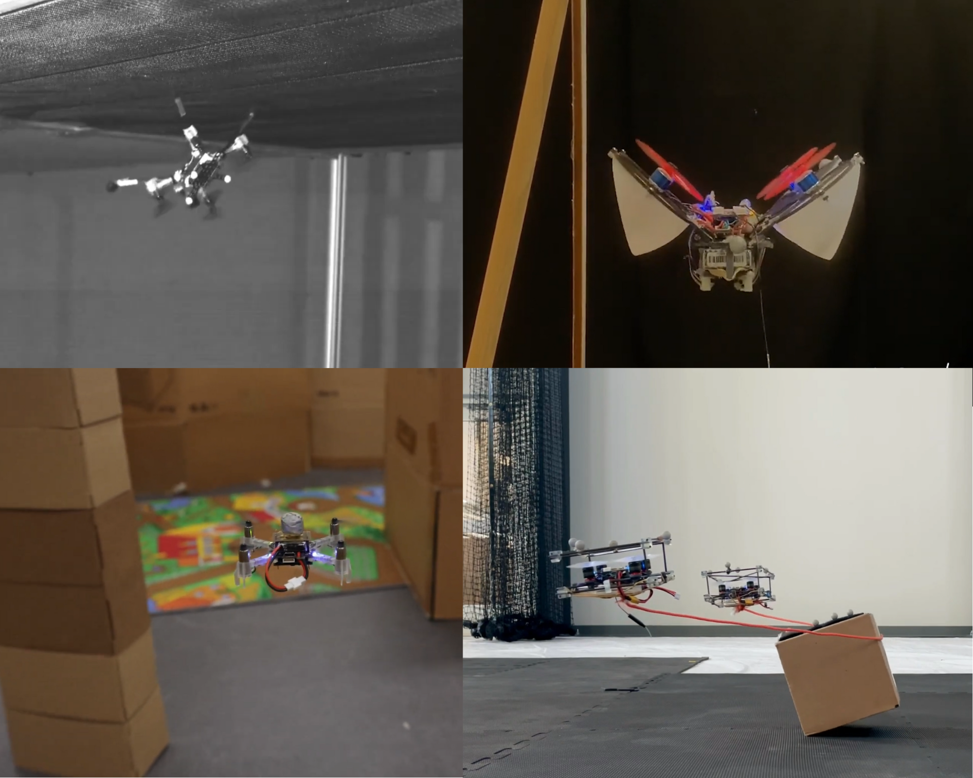
It’s time for a new compilation video about how the Crazyflie is used in research ! The last one featured already a lot of awesome work, but a lot happened since then, both in research and at Bitcraze.
As usual, the hardest about making those videos is choosing the works we want to feature – if every cool video of the Crazyflie was in there, it would last for hours! So it’s just a selection of the most videogenic projects we’ve seen. You can find a more extensive list of our products used in research here.
We’ve seen a lot of projects that used the modularity of the Crazyflie to create awesome new features, like a catenary robot, some wall tracking or having it land upside down. The Crazyflie board was even made into a revolving wing drone. New sensors were used, to sniff out gas leaks (the Sniffy bug as seen in this blogpost), or to allow autonomous navigation. Swarms are also a research topic where we see a lot of the Crazyflie, this time for collision avoidance, or path planning. We also see more and more of simulators, which are used for huge swarms or physics tests.
Once again, we were surprised and awed by all the awesome things that the community did with the Crazyflie. Hopefully, this will inspire others to think of new things to do as well. We hope that we can continue with helping you to make your ideas fly, and don’t hesitate to share with us the awesome projects you’re working on!
Here is a list of all the research that has been included in the video:
My name is Hanna, and I just started as an intern at Bitcraze. However, it is not my first time working with a drone or even the Crazyflie, so I’ll tell you a bit about how I ended up here.
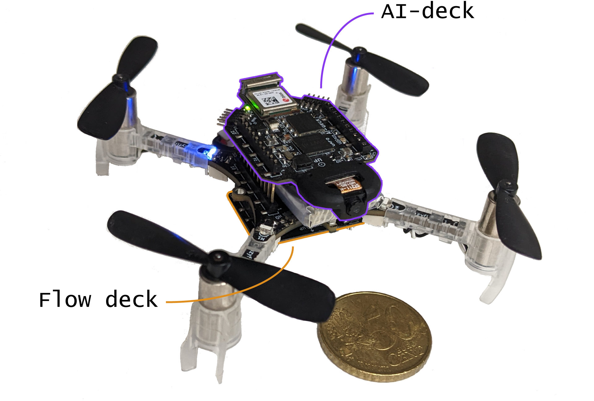
The first time I used a drone, actually even a Crazyflie, was in a semester thesis at ETH Zurich in 2017, where my task was to extend a Crazyflie with a Parallel Ultra Low-Power (PULP) System-on-Chip (SoC) connected to a camera and external memory. This was the first prototype of the AI-deck you can buy here nowadays (as used here) :)
My next drone adventure was an internship at a company building tethered drones for firefighters – a much bigger system than the Crazyflie. I was in charge of the update system, so more on the firmware side this time. It was a very interesting experience, but I swore never to build a system with more than three microcontrollers in it again.
This and a liking for tiny and restricted embedded systems brought me back to the smaller drones again. I did my master thesis back at ETH about developing a PULP-based nano-drone (nano-drones are just tiny drones that fit approximately in the palm of your hand and use only around 10Watts of power, the category Crazyflies fit in) and some onboard intelligence for it. As a starting point, we used the Crazyflie, both for the hardware and the software. It turned out to be a very hard task to port the firmware to a processor with only a very basic operating system at that time. Still, eventually I knew almost every last detail of the Crazyflie firmware, and it actually flew.
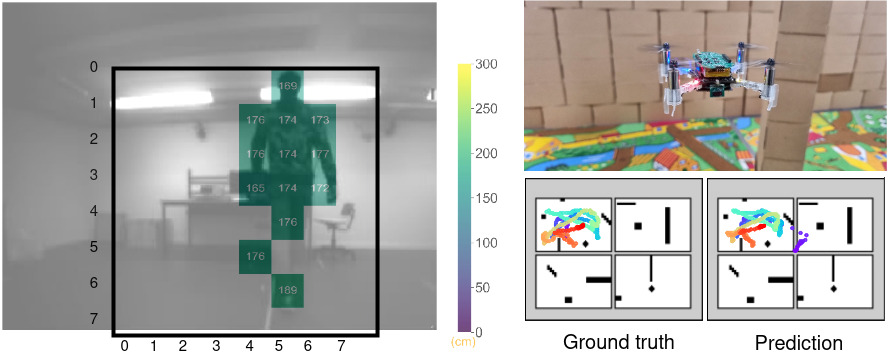
However, for this to happen, I needed some more time than the master thesis – in the meantime, I started to pursue a PhD at ETH Zurich. I am working towards autonomous miniaturized drones – so besides the part with the tiny PULP-based drone I already told you about, I also work on the “autonomous” part. Contrary to many other labs our focus is not only on novel algorithms though, we also work with novel sensors and processors. Two very interesting recent developments for us are a multi-zone Time-of-Flight sensor and the novel gap9 processor, which both fit on a Crazyflie in terms of power, size and weight. This enables new possibilities in obstacle avoidance, localization, mapping and many more. Last year my colleagues and I already posted a blog post about our newest advances in obstacle avoidance (here, with Videos!). More recently, we worked on onboard localization, using novel multi-zone Time-of-Flight sensors and the very new GAP9 processor to execute Monte Carlo localization onboard a Crazyflie (arxiv).
On the left you see an example of a multi-zone Time-of-Flight image (the background is a picture from the AI-deck), from here. On the right you see our prototype for localization in action – from our DATE23 paper (arxiv).
For me, localizing with a given map is a fascinating topic and one of the reasons I ended up in Sweden. It is one of the most basic skills of robots or even humans to navigate from A to B as fast as possible, and the basis of my favourite sport. The sport is called “orienteering” and is about running as fast as possible to some checkpoints on a map, usually through a forest. It is a very common sport in Sweden, which is the reason I started learning Swedish some years ago. So when the opportunity to go to Malmö for some months to join Bitcraze presented itself, I was happy to take it – not only because I like the company philosophy, but also because I just like to run around in Swedish forests :)
Now I am looking forward to my time here, I hope to learn lots about drones, firmware, new sensors, production, testing, company organization and to meet a lot of new nice people!
Greetings from Malmö – it can be a bit cold and rainy, but the sea and landscape are beautiful!
Bats navigate using sound. As a matter of fact, the ears of a bat are so much better developed than their eyes that bats cope better with being blindfolded than they cope with their ears being covered. It was precisely this experiment that helped the discovery of echolocation, which is the principle bats use to navigate [1]. Broadly speaking, in echolocation, bats emit ultrasonic chirps and listen for their echos to perceive their surroundings. Since its discovery in the 18th century, astonishing facts about this navigation system have been revealed — for instance, bats vary chirps depending on the task at hand: a chirp that’s good for locating prey might not be good for detecting obstacles and vice versa [2]. Depending on the characteristics of their reflected echos, bats can even classify certain objects — this ability helps them find, for instance, water sources [3]. Wouldn’t it be amazing to harvest these findings in building novel navigation systems for autonomous agents such as drones or cars?
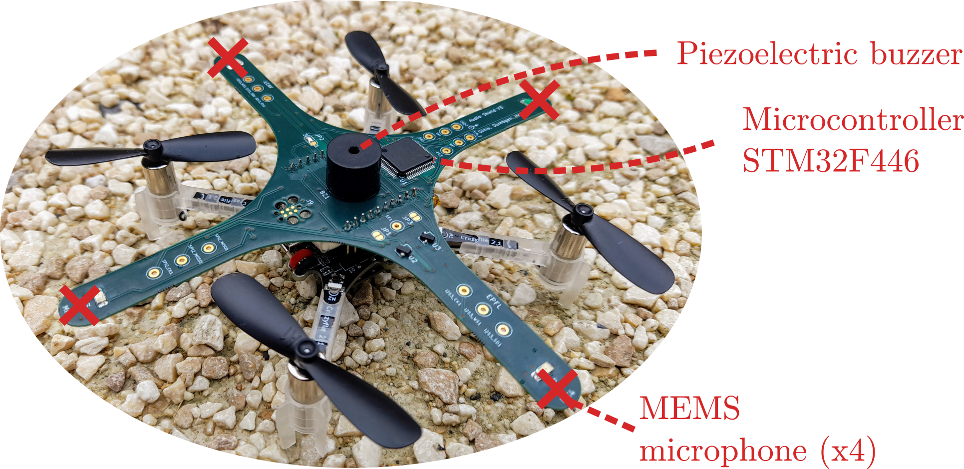
Figure 1: Meet “Crazybat”: the Crazyflie equipped with our custom audio deck including 4 microphones, a buzzer, and a microcontroller. Together, they can be used for bat-like echolocation. The design files and firmware of the audio extension deck are openly available, as is a ROS2-based software stack for audio-based navigation. We hope that fellow researchers can use this as a starting point for further pushing the limits of audio-based navigation in robotics. More details can be found in [4].
The quest for the answer to this question led us — a group of researchers from the École Polytechnique Fédérale de Lausanne (EPFL) — to design the first audio extension deck for the Crazyflie drone, effectively turning it into a “Crazybat” (Figure 1). The Crazybat has four microphones, a simple piezo buzzer, and an additional microprocessor used to extract relevant information from audio data, to be sent to the main processor. All of these additional capabilities are provided by the audio extension deck, for which both the firmware and hardware design files are openly available.1
Video 1: Proof of concept of distance/angle estimation in a semi-static setup. The drone is moved using a stepper motor. More details can be found in [4].
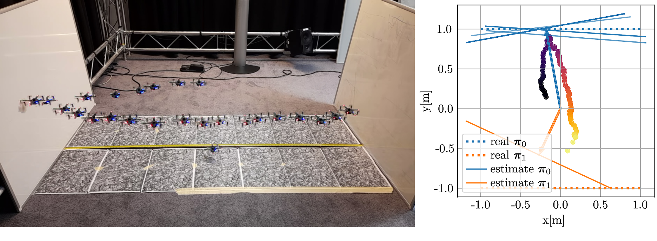
In our paper on the system [4], we show how to use chirps to detect nearby obstacles such as glass walls. Difficult to detect using a laser or cameras, glass walls are excellent sound reflectors and thus a good candidate for audio-based navigation. We show in a first semi-static feasibility study that we can locate the glass wall with centimeter accuracy, even in the presence of loud propeller noise (Video 1). When moving to a flying drone and different kinds of reflectors, the problem becomes significantly more challenging: motion jitter, varying propeller noise and tight real-time constraints make the problem much harder to solve. Nevertheless, first experiments suggest that sound-based wall detection and avoidance is possible (Figure and Video 2).
Video 2: The “Crazybat” drone actively avoiding obstacles based on sound. Figure 2: Qualitative results of sound-based wall localization on the flying “Crazybat” drone. More details can be found in [4].
The principle we use to make this work is sound-based interference. The sound will “bounce off” the wall, and the reflected and direct sound will interfere either constructively or destructively, depending on the frequency and distance to the wall. Using this same principle for the four microphones, both the angle and the distance of the closest wall can be estimated. This is however not the only way to navigate using sound; in fact, our software stack, available as an open-source package for ROS2, also allows the Crazybat to extract the phase differences of incoming sound at the four microphones, which can be used to determine the location of an external sound source. We believe that a truly intelligent Crazybat would be able to switch between different operating modes depending on the conditions, just like bats that change their chirps depending on the task at hand.
Note that the ROS2 software stack is not limited to the Crazybat only — we have isolated the hardware-dependent components so that the audio-based navigation algorithms can be ported to any platform. As an example, we include results on the small wheeled e-puck2 robot in [4], which shows better performance than the Crazybat thanks to the absence of propeller noise and motion jitter.
This research project has taught us many things, above all an even greater admiration for the abilities of bats! Dealing with sound is pretty hard and very different from other prevalent sensing modalities such as cameras or lasers. Nevertheless, we believe it is an interesting alternative for scenarios with poor eyesight, limited computing power or memory. We hope that other researchers will join us in the quest of exploiting audio for navigation, and we hope that the tools that we make publicly available — both the hardware and software stack — lower the entry barrier for new researchers.
1 The audio extension deck works in a “plug-and-play” fashion like all other extension decks of the Crazyflie. It has been tested in combination with the flow deck, for stable flight in the absence of a more advanced localization system. The deck performs frequency analysis on incoming raw audio data from the 4 microphones, and sends the relevant information over to the Crazyflie drone where it is converted to the CRTP protocol on a custom driver and sent to the base station for further processing in the ROS2 stack.
References
[1] Galambos, Robert. “The Avoidance of Obstacles by Flying Bats: Spallanzani’s Ideas (1794) and Later Theories.” Isis 34, no. 2 (1942): 132–40. https://doi.org/10.1086/347764.
[2] Fenton, M. Brock, Alan D. Grinnell, Arthur N. Popper, and Richard R. Fay, eds. “Bat Bioacoustics.” In Springer Handbook of Auditory Research, 1992.https://doi.org/10.1007/978-1-4939-3527-7.
[3] Greif, Stefan, and Björn M Siemers. “Innate Recognition of Water Bodies in Echolocating Bats.” Nature Communications 1, no. 106 (2010): 1–6. https://doi.org/10.1038/ncomms1110.
[4] F. Dümbgen, A. Hoffet, M. Kolundžija, A. Scholefield and M. Vetterli, “Blind as a Bat: Audible Echolocation on Small Robots,” in IEEE Robotics and Automation Letters (Early Access), 2022. https://doi.org/10.1109/LRA.2022.3194669.
Announcement: We will have a townhall meeting this Wednesday (7th of December) about Crazyradio 2.0 and the ideas about the new com-stack at 15:00 (3 pm) CET. Please follow the discussion here for more info.
As you have been very much aware of already if you have been reading the blog occasionally is that we went to Japan with the entire company to be at the International Conference on Intelligent Robots and Systems (IROS) in Kyoto, Japan. Besides eating great food, singing karaoke, and herding our fully onboard autonomous swarm at our stand, we also had some time to check out what kind of work was done with the Crazyflie in the proceeding papers and talks!
So just some generic statistics first:
IROS had 1716 papers accepted
We found 14 Crazyflie papers/posters and 2 workshop papers
The three biggest topics we found the papers in were: SLAM, Multi-robot systems and Navigation & Motion planning, SLAM
At ICRA this year, we noticed that the Crazyflie/bolt were used to make unconventional platforms, like a mono-copter or transforming the Crazyflie to a Pogo stick. It was interesting to see that now at IROS, the focus seemed to be more on navigation, localization and even SLAM… also with unconventional sensors!
Navigation and SLAM with the Crazyflie
In the summer I (Kim) worked on a summer project with using ROS2 to try SLAM with the standard packages with the Flow deck and Multi-ranger. This was also to present the work at ROScon before that with the Crazyswarm2 project, the Crazyflie can be used as an actual robotic platform too! I’m glad that some researchers already figured this one out already, as there were quite some papers on SLAM! [6] and [12] made use of the flow & multi-ranger but made their own custom algorithms to do SLAM and mapping that was more tailored to the task than the standard SLAM packages out there meant for 360 degree lidars.
Very interestingly, there were several papers that uses unconventional sensors for this as well. [5] used a gas sensor to do both gas source localization and distributing mapping and [10] made their own echolocation deck with buzzer + microphones. Let’s see what other sensors will be explored in the future!
Safe Robot Learning Competition
A special mention goes to the Safe Robot Learning competition, organized by the joined TU Munich and Utoronto’s the Learning system & robotics lab (formally known as the Dynamic Systems lab). In this competition, teams could participate with an online competition where they had to finish an obstacle course in simulation. From those that were successful, the finals were done with a real Crazyflie at a remote testbed in the University of Toronto, where the algorithms were put to the ultimate test! The simulation was done in the safe-control-gym framework [12], and the communication with the real Crazyflie was done with the ROS1 based Crazyswarm. We sponsored the first three places with a couple of Crazyflie bundles, so congrats to the winners!
List of IROS 2022 Papers featuring the Crazyflie
Using Simulation Optimization to Improve Zero-shot Policy Transfer of Quadrotors Sven Gronauer, Matthias Kissel, Luca Sacchetto, Mathias Korte and Klaus Diepold
Polynomial Time Near-Time-Optimal Multi-Robot Path Planning in Three Dimensions with Applications to Large-Scale UAV Coordination Teng Guo, Siwei Feng and Jingjin Yu
Avoiding Dynamic Obstacles with Real-time Motion Planning using Quadratic Programming for Varied Locomotion Modes Jason White, David Jay, Tianze Wang, and Christian Hubicki
Safe Reinforcement Learning for Robot Control using Control Lyapunov Barrier Functions Desong Du, Shaohang Han, Naiming Qi and Wei Pan
Harbin Institute of Technology + TU Delft + University of Manchester
Late breaking result poster
Parsing Indoor Manhattan Scenes Using Four-Point LiDAR on a Micro UAV Eunju Jeong, Suyoung Kang, Daekyeong Lee, and Pyojin Kim
Sookmyung Women’s University,
Late breaking result poster
Interactive Multi-Robot Aerial Cinematography Through Hemispherical Manifold Coverage Xiaotian Xu , Guangyao Shi , Pratap Tokekar , and Yancy Diaz-Mercado
University of Maryland
Note: Only mention of Crazyflie experiments in presentation
Safe-control-gym: a Unified Benchmark Suite for Safe Learning-based Control and Reinforcement Learning in Robotics Zhaocong Yuan, Adam W. Hall, Siqi Zhou, Lukas Brunke, Melissa Greeff, Jacopo Panerati, Angela P. Schoellig
Customizable-ModQuad: a Versatile Hardware-Software Platform to Develop Lightweight and Low-cost Aerial Vehicles Diego S. D’Antonio, Jiawei Xu, Gustavo A. Cardona, and David Saldaña
Let us know if we are missing any papers or information per papers! Once the IEEE xplore IROS 2022 proceedings have been published, we will update these too and put them on our research page.
Tiny quadcopters like the Crazyflie can be operated in narrow, cluttered environments and in proximity to humans, making them the perfect candidate for search-and-rescue operations, monitoring of crop in a greenhouse, or performing inspections where other flying robots cannot reach. All these applications benefit from autonomy, allowing deployment without proximity to a base station or human operator and permitting swarming behavior.
Achieving autonomous navigation on nano quadcopters is challenging given the highly constrained payload and computational power of the platform. Most attention has been given to monocular solutions; the camera is a lightweight and energy-efficient passive sensor that captures rich information of the environment. One of the most important monocular visual cues is optical flow, which has been exploited on MAVs with higher payload for obstacle avoidance [1], depth estimation [2] and several bio-inspired methods for autonomous navigation [3–7].
Optical flow describes the apparent visual variations caused by relative motion between an observer and their surroundings. This rich visual cue contains tangled information of velocity and depth. However, calculating optical flow is expensive. The field of optical flow estimation is and has been for a couple of years dominated by convolutional neutral networks (CNNs). Despite efforts to find architectures of reduced size and latency [8-10], these methods are still highly computationally expensive, running at several to tens of FPS on modern desktop GPUs and requiring millions of parameters to run, rendering them incompatible with edge hardware.
To this end, we present “NanoFlowNet: Real-Time Dense Optical Flow on a Nano Quadcopter”, submitted to an international robotics conference, which introduces NanoFlowNet, a CNN architecture designed for real-time, fully on-board, dense optical flow estimation on the AI-deck.
CNN architecture
We adopt semantic segmentation CNN STDC-Seg [11] and modify it for optical flow estimation. The resulting CNN architecture may be considered “real-time” on desktop hardware, for deployment on edge devices such as a nano quadcopter the net must be significantly shrunk. We improve the latency of the architecture in three ways.
First, we redesign the key convolutional modules of the architecture, the Short-Term Dense Concatenate (STDC) module. By reordering the operations within the strided variant of the module, we save, depending on the location of the module within the architecture, from over 10% to over 50% of the MAC operations per module, while increasing the number of output filters with large receptive field size. A large receptive field size is desirable for optical flow estimation.
Second, inspired by MobileNets [12], we globally replace ‘regular’ convolutions with depthwise separable convolutions. Depthwise separable convolutions factorize a convolution into a depthwise and pointwise convolution, effectively reducing the calculational expense at a cost in representational capacity.
Third, we reduce the input dimensionality. We train and infer network on grayscale input images, reducing the required on-board memory for storing images by a factor 2/3. Any memory saved on the AI-deck’s L2 memory can be handed to AutoTiler for storing the CNN architecture, speeding up the on-board execution. Requiring more of a speed-up, we run the CNN on-board at a reduced input resolution of 160×112 pixels. Besides the speed-up through saved L2, reducing the input resolution makes all operations throughout the network cheaper. We downscale training data to closely match the target resolution. Both these changes come at a loss of input information. We will miss out on small objects and small displacements that are not captured by the resolution.
To give some intuition of the available memory: Estimating optical flow requires two input images. Storing two color input images at full resolution requires (2 x 324x324x3=) 630 kB. The AI-deck has 512 kB of L2 memory available.
Motion boundary detail guidance
Inspired by STDC-Seg, we guide the training of optical flow with a train-time-only auxiliary task to promote the encoding of spatial information in the early layers. Specifically, we introduce a motion boundary prediction task to the net. The motion boundary ground truth can be found in the optical flow datasets. This improves performance by 0.5 EPE on the MPI Sintel clean (train) benchmark, at zero cost to inference latency.
Performance on MPI Sintel
Given the scaling and conversion to grayscale of input data, our network is not directly comparable with results reported by other works. For comparison, we retrain one of the fastest networks in literature, Flownet2-s [13], on the same data. Given the reduction in resolution, we drop the deepest two layers to maintain a reasonable feature size. We name the model Flownet2-xs.
We benchmark the performance of the architecture on the optical flow dataset MPI Sintel. NanoFlowNet performs better than FlowNet2-xs, despite using less than 10% of the parameters. NanoFlowNet achieves 5.57 FPS on the AI-deck. FlowNet2-xs does not fit on the AI-deck due to the network size. To put the achieved latency of NanoFlowNet in perspective, we execute FlowNet2-xs’ first two convolutions and the final prediction layer on the GAP8. The three-layer architecture achieves 4.96 FPS, which is slower than running the entire NanoFlowNet. On a laptop GPU, the two architectures accomplish similar latency.
Method
MPI Sintel (train) [EPE]
Frame rate [FPS]
Parameters
Clean
Final
GPU
GAP8
FlowNet2-xs
9.054
9.458
150
–
1,978,250
NanoFlowNet
7.122
7.979
141
5.57
170,881
Performance on MPI Sintel (train subset). (Average) end-to-end Point Error (EPE) describes how far off the estimated flow vectors are on average, lower is better.
Input frame IGround truth optical flowNanoFlowNet (ours)FlowNet2-xsInput frame IGround truth optical flowNanoFlowNet (ours)FlowNet2-xsQualitative comparison of optical flow estimates by NanoFlowNet(-s) and FlowNet2-xs on MPI Sintel (train) clean pass. NanoFlowNet and NanoFlowNet-s pick up on smaller moving objects, such as the person in the bottom row.
Obstacle avoidance implementation
We demonstrate the effectiveness of NanoFlowNet by implementing it in a simple, proof-of-concept obstacle avoidance application on an AI-deck equipped Crazyflie. We let the quadcopter fly forward at constant velocity and implement the horizontal balance strategy [14], [15], where the quadcopter balances the optical flow in the left and right half plane by yawing.
We equip a Crazyflie with the Flow deck for positioning only. The total flight platform weighs 34 grams.
We augment the balance strategy by implementing active oscillations (a cyclic up-down movement), resulting in additional optical flow generated across the field of view. This is particularly helpful for avoiding obstacles in the direction of horizontal travel, since no optical flow is generated at the focus of expansion.
The obstacle avoidance implementation is demonstrated in an open and a cluttered environment in ‘the Cyber Zoo’, an indoor flight arena at the faculty of Aerospace Engineering at the Delft University of Technology. The control algorithm is most robust in the open environment, with the quadcopter managing to drain a full battery without crashing. In the cluttered environment, performance is more variable. Especially on occasions where obstacles are close to one another, the quadcopter tends to avoid the first obstacle successfully, only to turn straight into the second and crash into it. Adding a head-on collision detection based on FOE detection and divergence estimation (e.g., [7]) should help avoid obstacles in these cases.
Successful run in a cluttered environment in the Cyber Zoo. The Crazyflie manages to avoid collision until the battery is drained.
All in all, we consider the result a successful demonstration of the optical flow CNN. In future work, we expect to see applications that take more advantage of the resolution of the flow information.
Citation
Bouwmeester, R. J., Paredes-Vallés, F., De Croon, G. C. H. E. (2022). NanoFlowNet: Real-time Dense Optical Flow on a Nano Quadcopter. arXiv. https://doi.org/10.48550/arXiv.2209.06918
References
[1] Gao, P., Zhang, D., Fang, Q., & Jin, S. (2017). Obstacle avoidance for micro quadrotor based on optical flow. Proceedings of the 29th Chinese Control and Decision Conference, CCDC 2017, 4033–4037. https://doi.org/10.1109/CCDC.2017.7979206
[2] Sanket, N. J., Singh, C. D., Ganguly, K., Fermuller, C., & Aloimonos, Y. (2018). GapFlyt: Active vision based minimalist structure-less gap detection for quadrotor flight. IEEE Robotics and Automation Letters, 3(4), 2799–2806. https://doi.org/10.1109/LRA.2018.2843445
[3] Conroy, J., Gremillion, G., Ranganathan, B., & Humbert, J. S. (2009). Implementation of wide-field integration of optic flow for autonomous quadrotor navigation. Autonomous Robots, 27(3), 189–198. https://doi.org/10.1007/s10514-009-9140-0
[4] Zingg, S., Scaramuzza, D., Weiss, S., & Siegwart, R. (2010). MAV navigation through indoor corridors using optical flow. Proceedings – IEEE International Conference on Robotics and Automation, 3361–3368. https://doi.org/10.1109/ROBOT.2010.5509777
[5] De Croon, G. C. H. E. (2016). Monocular distance estimation with optical flow maneuvers and efference copies: A stability-based strategy. Bioinspiration and Biomimetics, 11(1). https://doi.org/10.1088/1748-3190/11/1/016004
[6] Serres, J. R., & Ruffier, F. (2017). Optic flow-based collision-free strategies: From insects to robots. Arthropod Structure and Development, 46(5), 703–717. https://doi.org/10.1016/j.asd.2017.06.003
[7] De Croon, G. C. H. E., De Wagter, C., & Seidl, T. (2021). Enhancing optical-flow-based control by learning visual appearance cues for flying robots. Nature Machine Intelligence, 3(1), 33–41. https://doi.org/10.1038/s42256-020-00279-7
[8] Ranjan, A., & Black, M. J. (2017). Optical flow estimation using a spatial pyramid network. Proceedings – 30th IEEE Conference on Computer Vision and Pattern Recognition, 2720–2729. https://doi.org/10.1109/CVPR.2017.291
[9] Hui, T. W., Tang, X., & Loy, C. C. (2018). LiteFlowNet: A Lightweight Convolutional Neural Network for Optical Flow Estimation. Proceedings of the IEEE Computer Society Conference on Computer Vision and Pattern Recognition, 8981–8989. https://doi.org/10.1109/CVPR.2018.00936
[10] Sun, D., Yang, X., Liu, M. Y., & Kautz, J. (2017). PWC-Net: CNNs for Optical Flow Using Pyramid, Warping, and Cost Volume. Proceedings of the IEEE Computer Society Conference on Computer Vision and Pattern Recognition, 8934–8943. https://doi.org/10.1109/CVPR.2018.00931
[11] Fan, M., Lai, S., Huang, J., Wei, X., Chai, Z., Luo, J., & Wei, X. (2021). Rethinking BiSeNet For Real-time Semantic Segmentation. Proceedings of the IEEE Computer Society Conference on Computer Vision and Pattern Recognition, 9711–9720. https://doi.org/10.1109/CVPR46437.2021.00959
[12] Howard, A. G., Zhu, M., Chen, B., Kalenichenko, D., Wang, W., Weyand, T., Andreetto, M., & Adam, H. (2017). MobileNets: Efficient Convolutional Neural Networks for Mobile Vision Applications. In arXiv. arXiv. http://arxiv.org/abs/1704.04861
[13] Ilg, E., Mayer, N., Saikia, T., Keuper, M., Dosovitskiy, A., & Brox, T. (2017). FlowNet 2.0: Evolution of optical flow estimation with deep networks.Proceedings – 30th IEEE Conference on Computer Vision and Pattern Recognition, 1647–1655. https://doi.org/10.1109/CVPR.2017.179
[14] Souhila, K., & Karim, A. (2007). Optical flow based robot obstacle avoidance. International Journal of Advanced Robotic Systems, 4(1), 2. https://doi.org/10.5772/5715
[15] Cho, G., Kim, J., & Oh, H. (2019). Vision-based obstacle avoidance strategies for MAVs using optical flows in 3-D textured environments. Sensors, 19(11), 2523. https://doi.org/10.3390/s19112523
This weeks guest blog post is from Hanna Müller, Vlad Niculescu and Tommaso Polonelli, who are working with Luca Benini at the Integrated Systems Lab and Michele Magno at the Center for Project-Based Learning, both at ETH Zürich. Enjoy!
This blog post will give you some insight into our current work towards autonomous flight on nano-drones using a miniaturized multi-zone depth sensor. Here we will mainly talk about obstacle avoidance, as it is our first building block towards fully autonomous navigation. Who knows, maybe in the future, we will have the honor to write another blog post about localization and mapping ;)
A Crazyflie 2.1 with our custom multi-zone ToF deck, a flow deck and a vicon marker.
Obstacle avoidance on nano-drones is challenging, as the restricted payload limits on-board sensors and computational power. Most approaches, therefore, use lightweight and ultra-low-power monocular cameras (as the AI-deck) or 1d depth sensors (as the multi-ranger deck). However, both those approaches have drawbacks – the camera images need extensive processing, usually even neural networks to detect obstacles. Neural networks additionally need training data and are prone to fail in completely new scenarios. The 1d depth sensors can reliably detect obstacles in their field of view (FoV); however, no information about the size or exact position of the obstacle is obtained.
On bigger drones, usually lidars or radars are used, but unfortunately, due to the limited weight and power consumption, those cannot be carried and used on nano-drones. However, in 2021 STMicroelectronics introduced a new multi-zone Time-of-Flight (ToF) sensor – with maximal 8×8 pixel resolution, a range up to 4m (according to the datasheet), a small form-factor and low power consumption of only 286mW (typical) it is ideal to use on nano-drones.
In the picture on top, you can see the Crazyflie 2.1 with our custom ToF deck (open-sourced at https://github.com/ETH-PBL/Matrix_ToF_Drones). We described this deck for the first time in [1], together with a sensor characterization. From this, we saw that we could use the sensor in different light conditions and on different colored obstacles, but from 2m on, the measurements started to get incomplete in all scenarios. However, as the sensor can detect invalid measurements (due to interference or obstacles being out of range), we can still rely on our information. In [2], we presented the system and some steps towards obstacle avoidance in a demo abstract, as you can see in the video below:
The next thing we did was to collect a dataset – we flew with different combinations of decks (flow-deck v2, AI-deck, our custom multi-zone ToF deck) and sometimes even tracked by a vicon system. Those recordings amount to an extensive dataset with depth images, RGB images, internal state estimation and the position and attitude ground truth.
We then fed the recorded data into a python simulation to develop an obstacle avoidance algorithm. We focused on only the ToF data (we are not fusing with the camera in this project, we just provide the data for future work). We aimed for a very efficient solution – because we want it to run on-board, on the STM32F405, with low latency and without occupying too many resources. Our algorithm is very lightweight but highly effective – we divide the FoV in different zones, according to how dangerous obstacles in those areas are and then use a decision tree to decide on a steering angle and velocity.
With only using up 0.31% of the computational power and 210 μs latency, we reached our goal of developing an efficient obstacle avoidance algorithm. Our system is also low-power, the power to lift the additional sensor with all accompanying electronics as well as the supply of it totals in less than 10% of the whole drone. On average, our system reaches a flight time of around 7 minutes. We refer to our preprint [3] for details on our various tests – they include flights with distances up to 212 m and 100% reliability and high agility at a low speed in an office environment.
As our paper is currently submitted but not yet accepted our code and dataset are not yet released – however, the hardware design is already accessible: https://github.com/ETH-PBL/Matrix_ToF_Drones
[1] V. Niculescu, H. Müller, I. Ostovar, T. Polonelli, M. Magno and L. Benini, “Towards a Multi-Pixel Time-of-Flight Indoor Navigation System for Nano-Drone Applications,” 2022 IEEE International Instrumentation and Measurement Technology Conference (I2MTC), 2022, pp. 1-6, doi: 10.1109/I2MTC48687.2022.9806701. [2] I. Ostovar, V. Niculescu, H. Müller, T. Polonelli, M. Magno and L. Benini, “Demo Abstract: Towards Reliable Obstacle Avoidance for Nano-UAVs,” 2022 21st ACM/IEEE International Conference on Information Processing in Sensor Networks (IPSN), 2022, pp. 501-502, doi: 10.1109/IPSN54338.2022.00051. [3] H.Müller, V. Niculescu, T. Polonelli, M. Magno and L. Benini “Robust and Efficient Depth-based Obstacle Avoidance for Autonomous Miniaturized UAVs”, submitted to IEEE, preprint: https://arxiv.org/abs/2208.12624