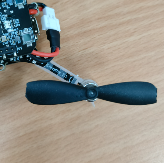
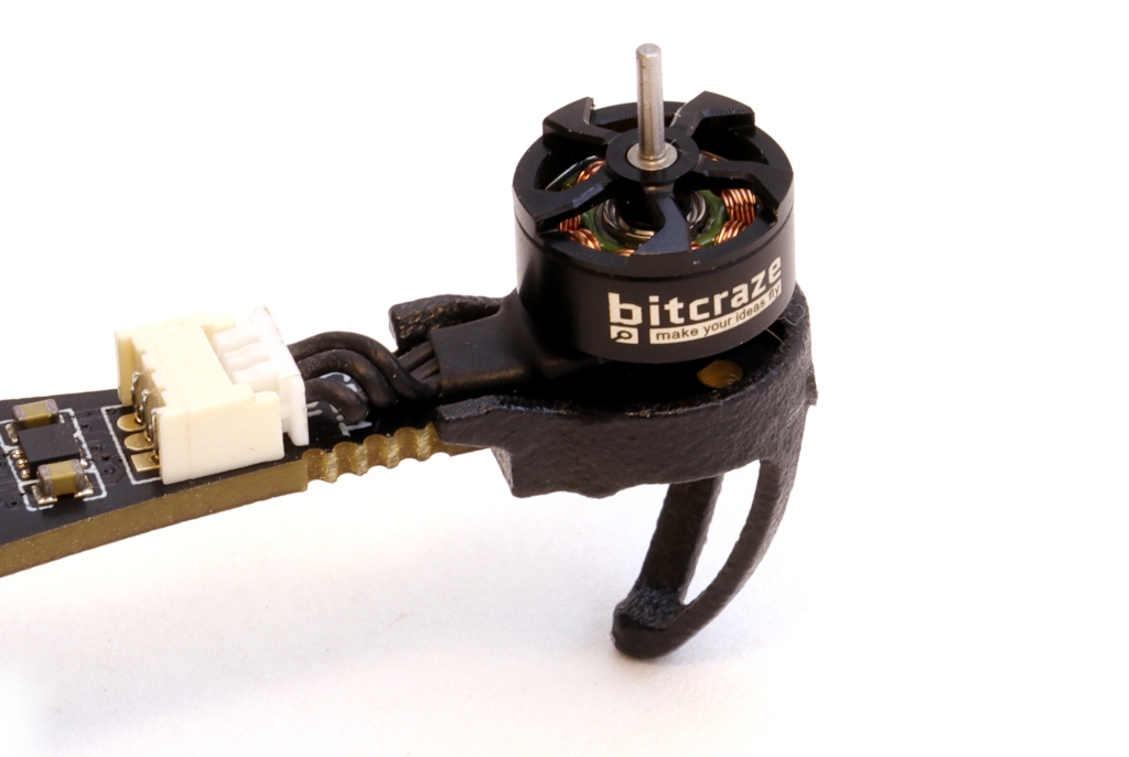
As 2024 comes to an end, it’s the perfect time to reflect on what we’ve accomplished over the past year. A major highlight has been our work on the Crazyflie 2.1 Brushless. We’re thrilled that it will be available early in the new year! While much of our efforts focused on refining and preparing the platform as a whole, we also introduced some standout features like support for contact charging on a charging pad, perfecting the specially optimized motors, and propeller guards to enhance safety for both users and the drone.
Finalizing the integration of the Crazyflie 2.1 Brushless into our software ecosystem and expanding its documentation were key steps in preparing for its launch. These efforts ensure compatibility, improve the user experience, and make the platform more accessible to the community. We’re looking forward to a smooth launch and to seeing how the community will utilize the new platform!
This year, we introduced updates to the Crazyflie 2.1 kit, making the 47-17 propellers the new default and including an improved battery. These upgrades enhance flight performance and endurance, culminating in the release of the Crazyflie 2.1+—an optimized iteration of our established platform.
Community
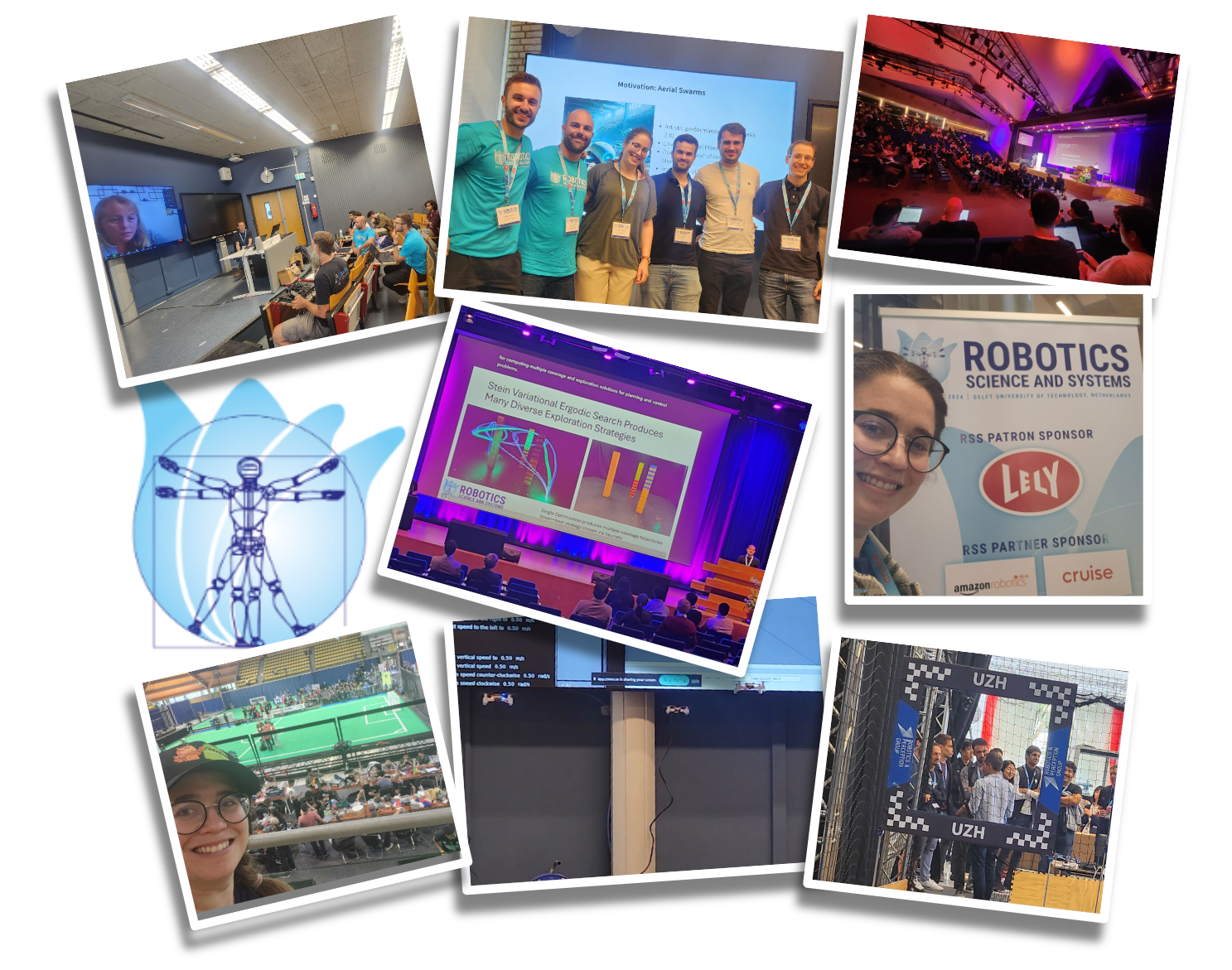
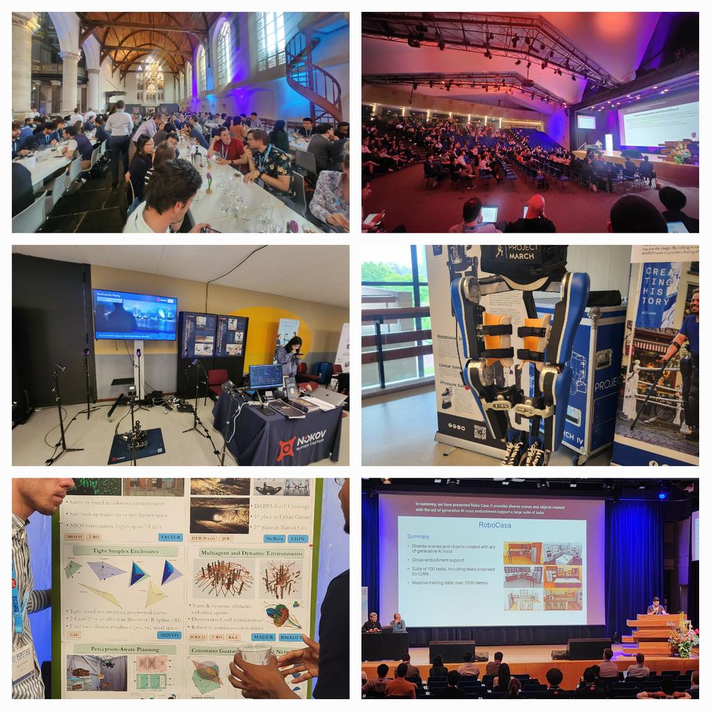
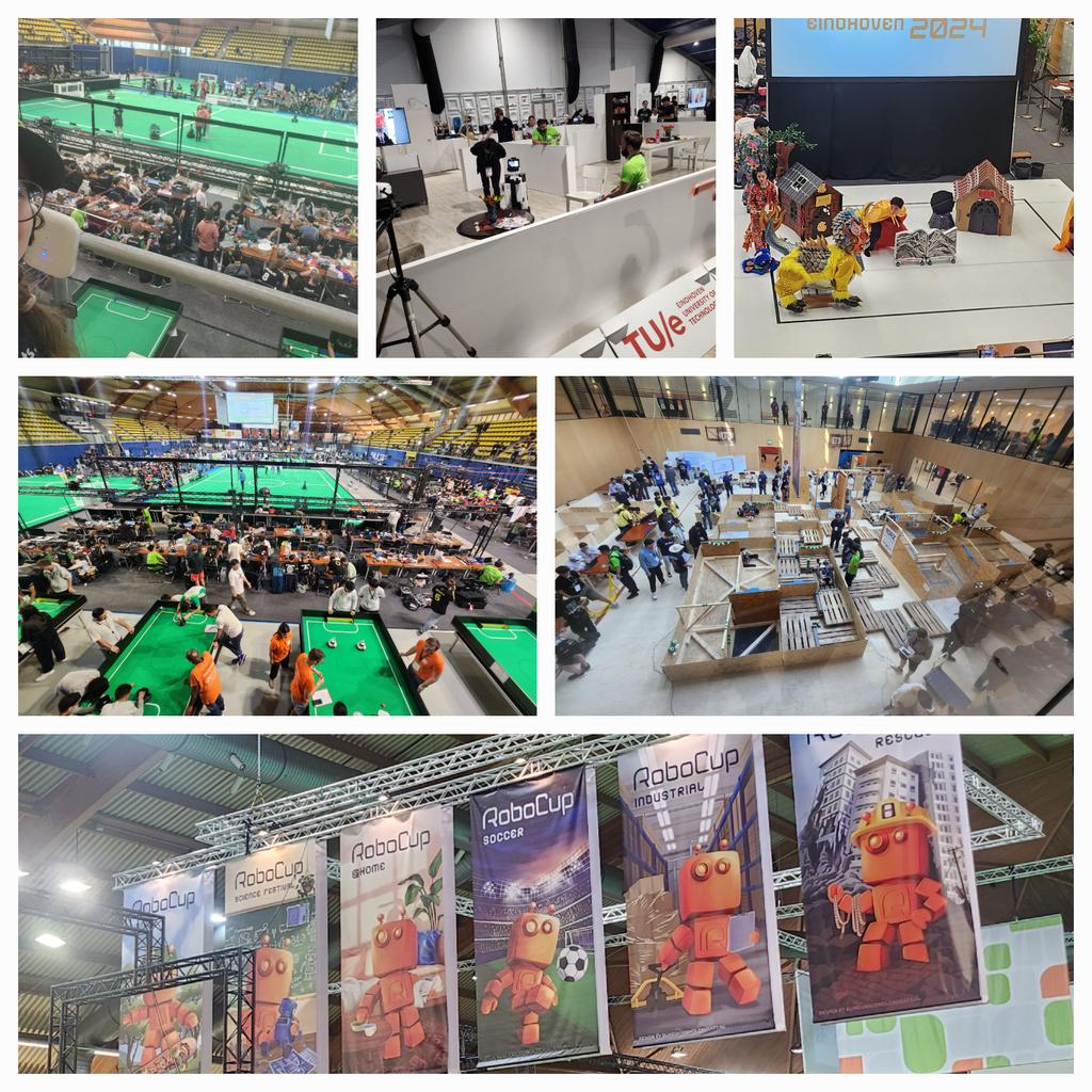
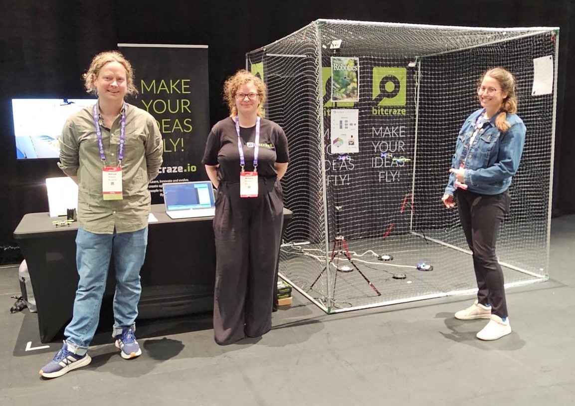
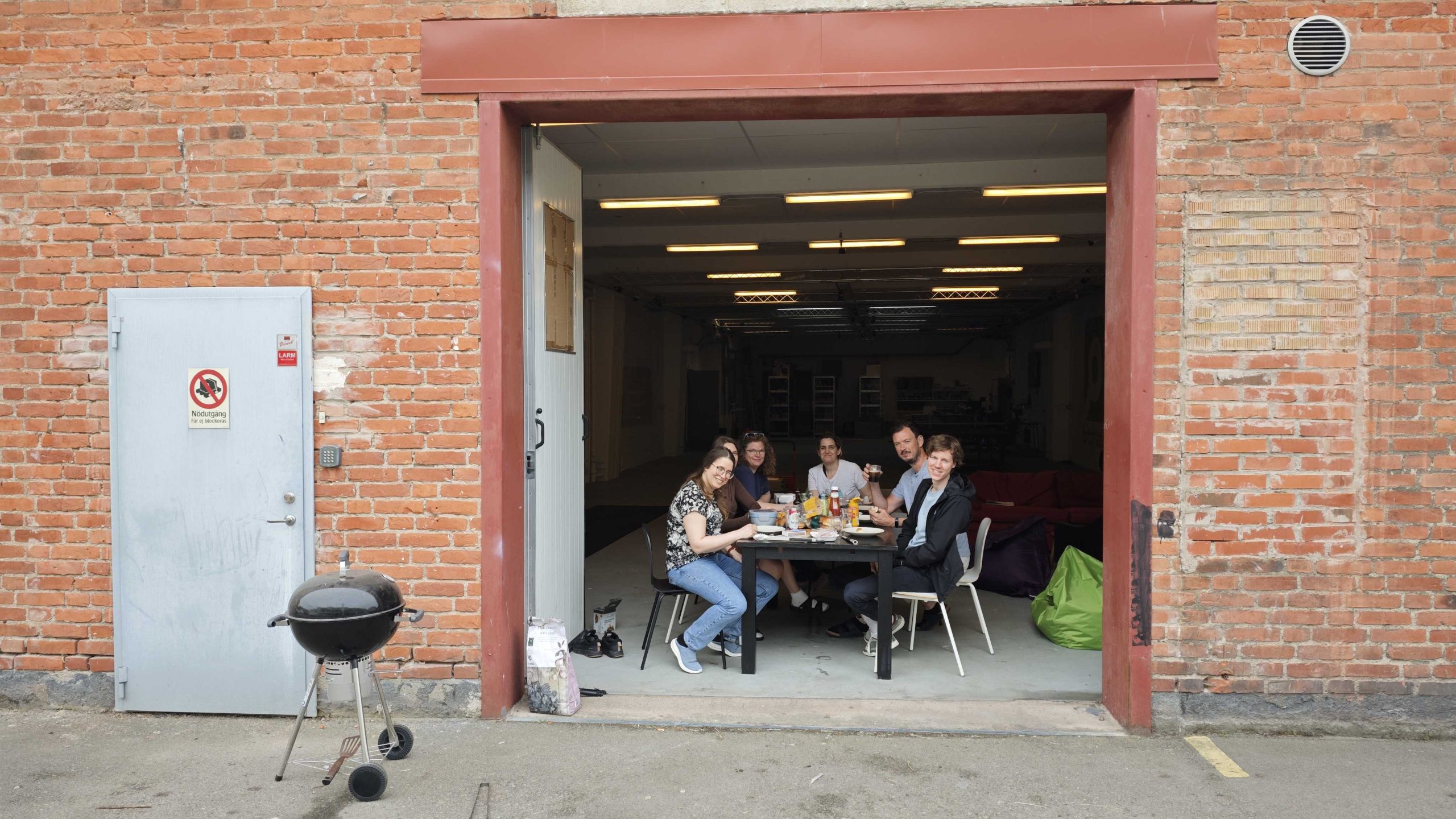
In 2024, Bitcraze had an action-packed year, engaging with the robotics community through numerous conferences, workshops, and live events.
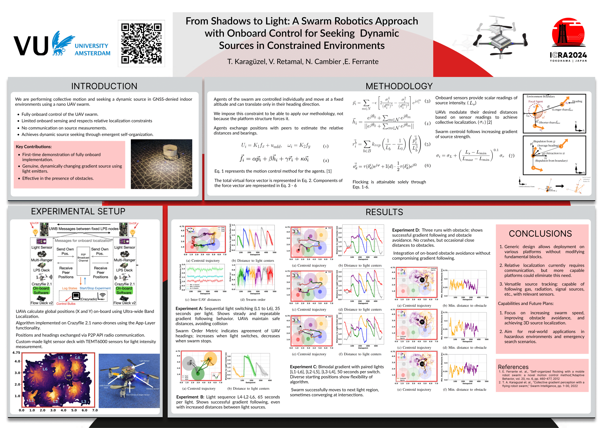
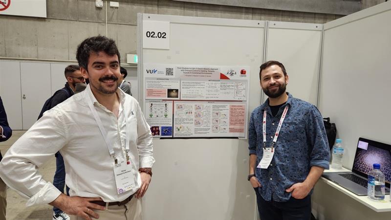
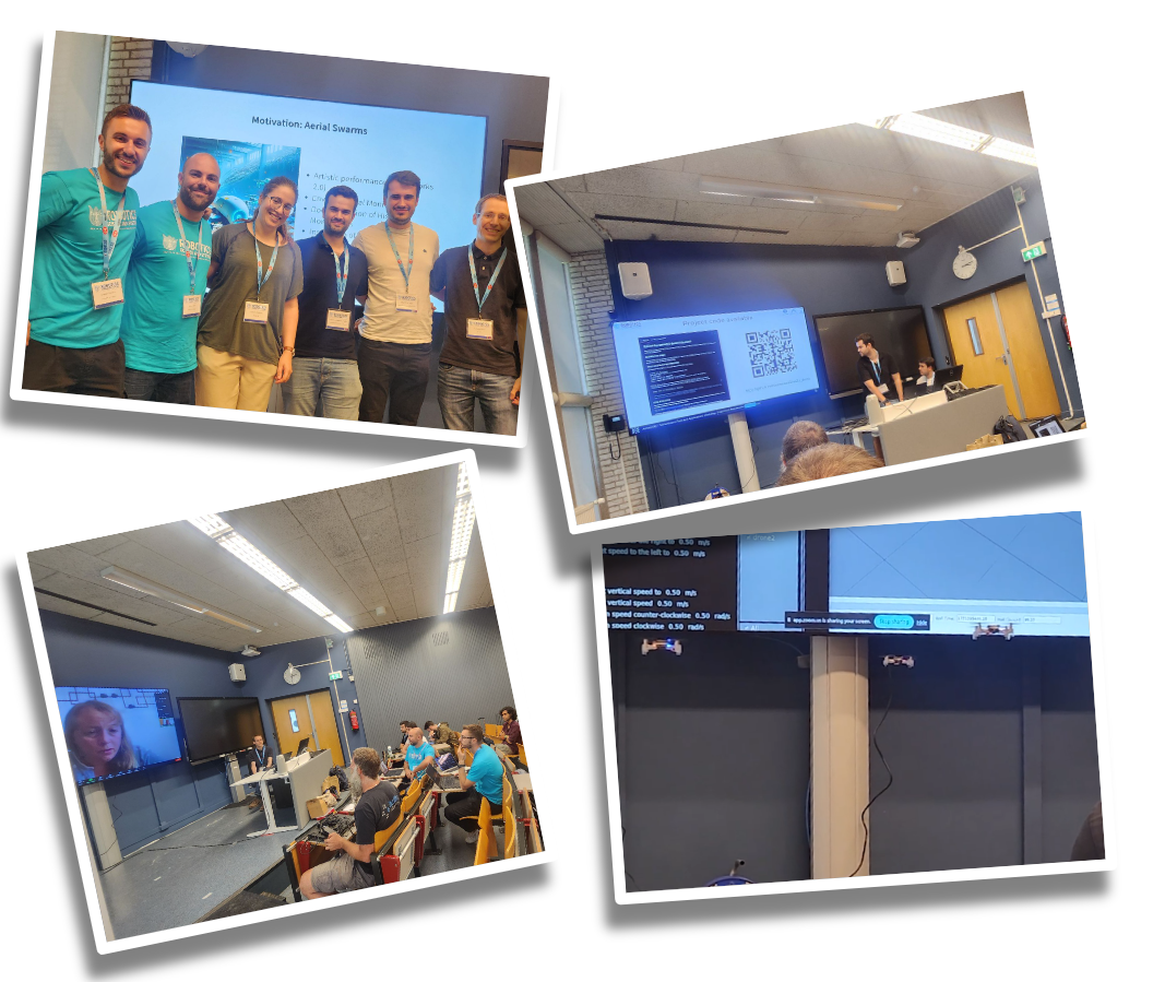
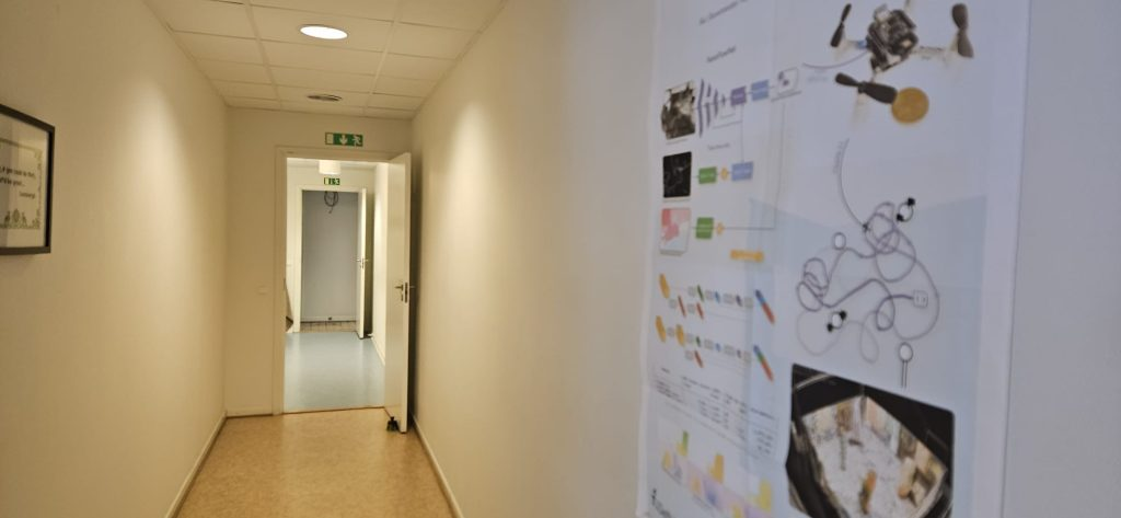
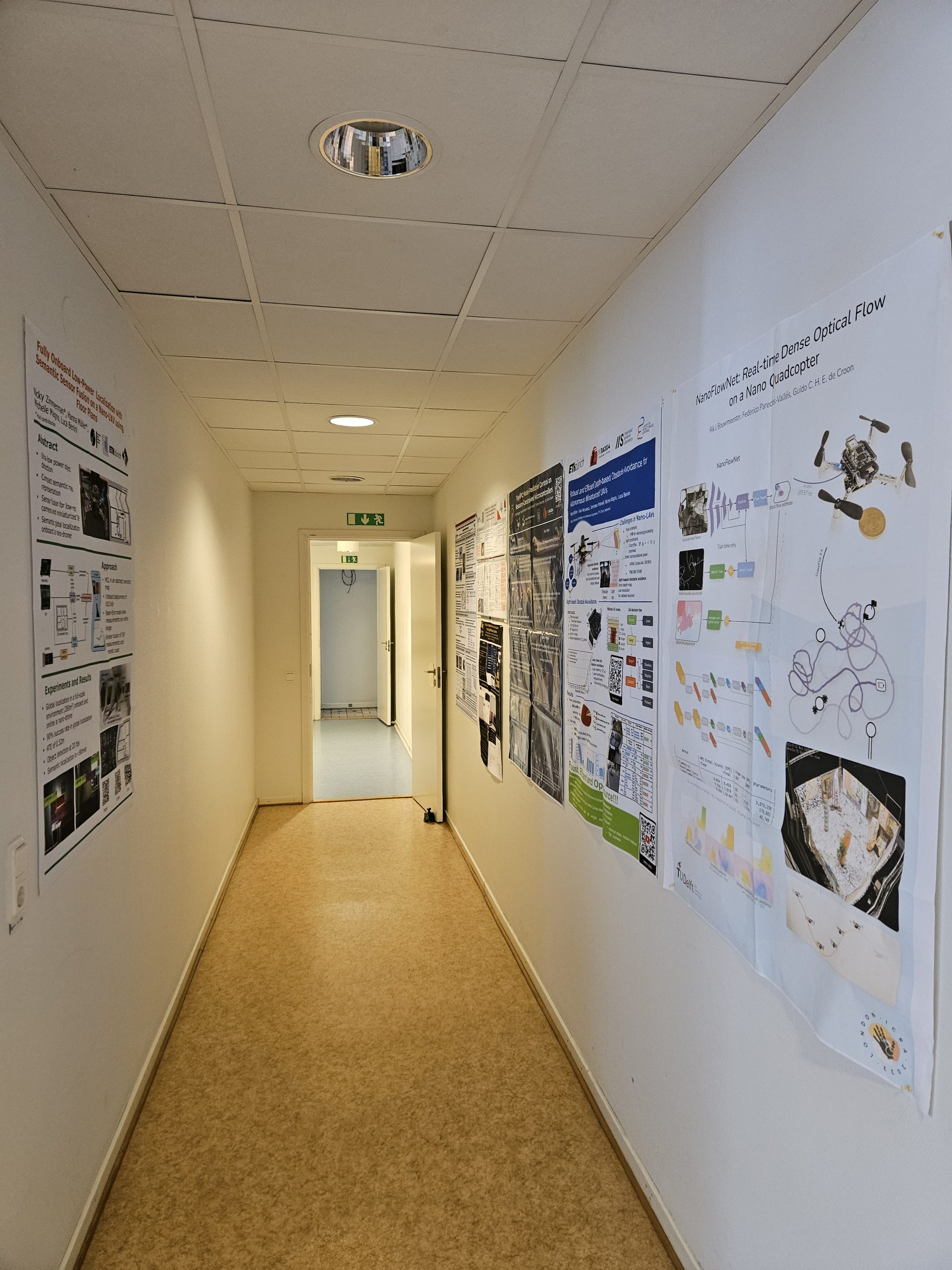
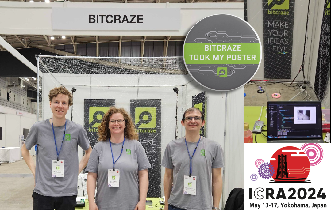
In May, we attended ICRA 2024 in Yokohama. We collected several research posters that now proudly feature at the office. Kimberly presented at the Robotics Developer Day, where she won Best Speaker Award for her impressive live hardware demos with ROS2. We co-organized the ‘Aerial Swarm Tools and Applications’ workshop at RSS 2024 in Delft. Arnaud and Kimberly shared insights on demo-driven development on an episode of OpenCV Live!. Additionally, we had a booth at ROSCon ’24 in Odense, connecting with the vibrant ROS community and showcasing our latest developments.
And don’t forget the developer meetings, where we shared some more behind the scenes information and collected invaluable feedback from the community.
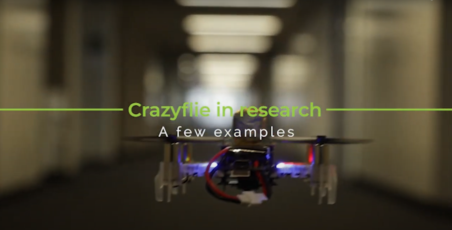
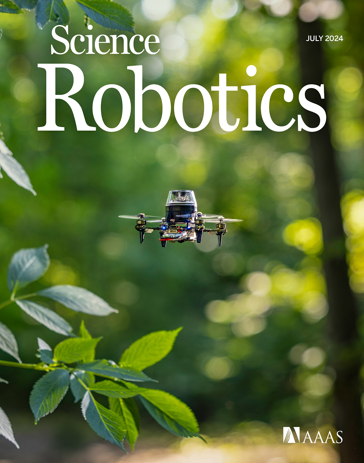
We also released a new edition of our research compilation video, showcasing some of the coolest projects from 2023 and 2024 that highlight the versatility and impact of the Crazyflie platform in research.
Team
In the past year, Bitcraze saw significant changes within the team. in February, Rik rejoined the team. Tove started at Bitcraze in April. Mandy, with whom we’ve already worked extensively over the years, joined as our production representative in Shenzen. At the end of the year, we said goodbye to Kimberly, whose contributions will be deeply missed. Additionally, we had Björn with us for a few months, working on his master’s thesis on fault detection, and Joe continued his industrial postdoc at Bitcraze that began in December 2023. Looking ahead, Bitcraze is hiring for two new roles: a Technical Sales Lead and a Technical Success Engineer, to support our ongoing projects and customer collaborations.
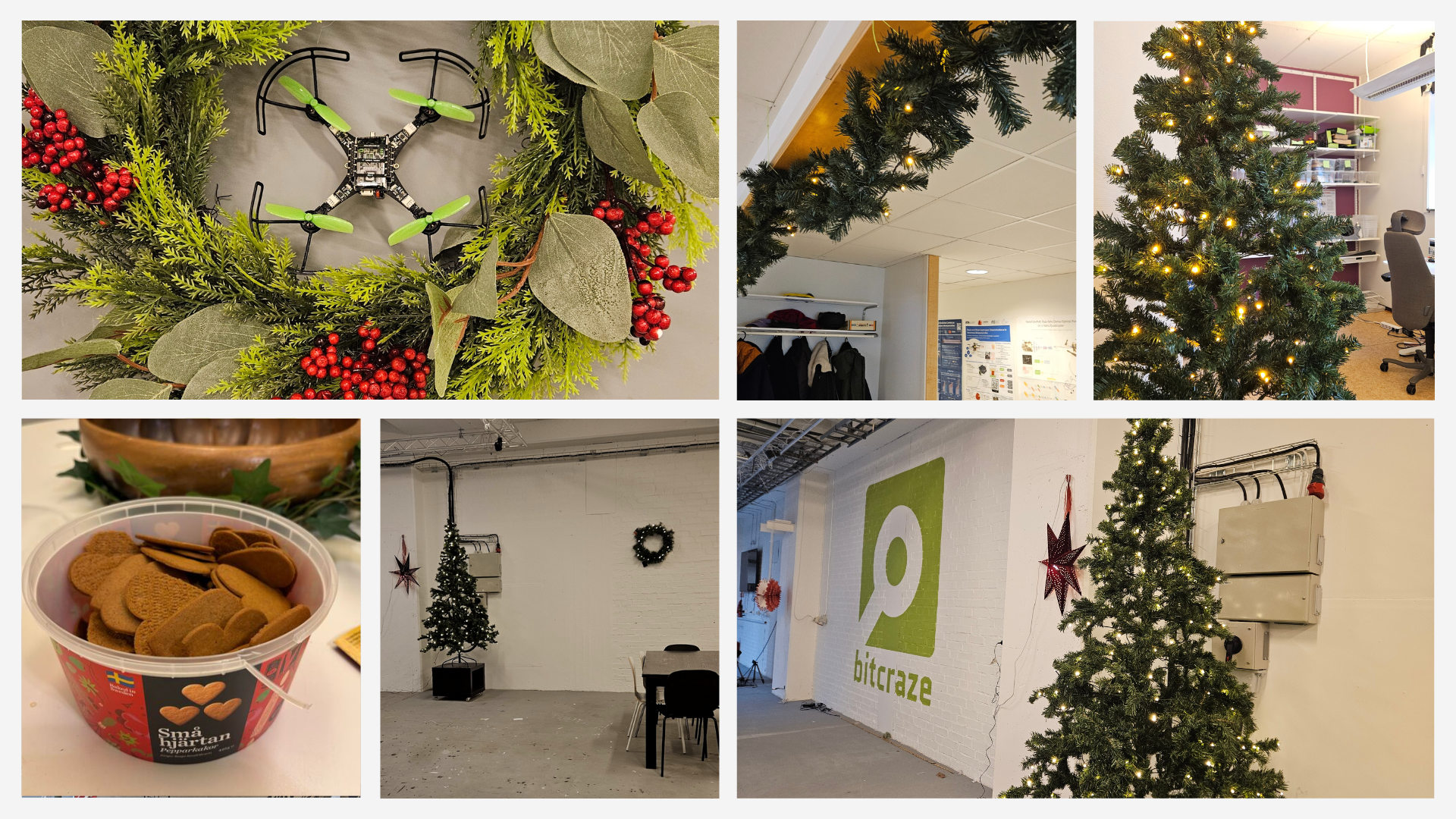
As we close the chapter on 2024, we’re proud of the progress we’ve made, the connections we’ve strengthened, and the milestones we’ve reached. With exciting launches, new faces on the team, and continued collaboration with our community, we’re ready to soar to even greater heights in 2025. Thank you for being part of our journey!