Hey there, my name is Zhouxin. I was born in the Netherlands and I still live there, but not for the upcoming four months since I am going to be an intern here, at Bitcraze. I am really looking forward to contribute and to be part of this team! In this blog post I will share with you my motivation of interning here and something about myself.
I am doing this internship as part of my studies at the TU Delft, an university in the Netherlands, but the main reason is that I like the technical challenges related to their product and the dynamic work environment. I am convinced that I can learn a lot here about the practical things like working in a tech company and also about the technical challenges when developing code for practical applications such as the Crazyflie 2.1.
As mentioned before this is part of my studies, at the moment I am studying for my Masters degree in Aerospace Engineering. In this degree there are profiles. I choose the profile Control and Simulation which is mainly focused on the control and navigation systems in aviation. This still sounds quite general, so I will give a few examples where you can think of. A graduate from this profile might work on the automatic pilot of an aircraft, on the simulators for pilot training, on air traffic management systems, or on autonomous micro air vehicles. The latter is something I am interested in and that’s one of the reasons I am doing my internship at Bitcraze.
As a child I was always intrigued by how birds can fly, this led to my desire to fly. I had tried flying several times by wearing a cape and by jumping of the couch while trying to optimize the airtime with flapping my cape. This gave me some adrenaline boost but I never was able to fly. Later I discovered that the only way for humans to fly is to become a pilot. This became my new dream. When I was about 8 years old I started to practice flying by controlling RC airplanes. This made me interested in electronics and technology which later translated into pursuing my degree in Aerospace Engineering.
Besides my academic interests I also occupy myself with other activities. About two years ago I took a gap year and went traveling in East Asia. There I have discovered my enjoyment of nature and exploring cultures. Also I love to snowboard in the French Alps during the winter holidays and to share these wintersport adventures with friends. When I am not traveling or abroad, I enthusiastically play field hockey or tennis.
We talked about it in a previous post, it is more than time to implement a higher abstraction layer for the Crazyflie firmware to make it easy to implement custom automations and programs on top of the flying platform. In this post we will try to explain the state of the art and where we are thinking of heading. This is mostly a request for comments and we are creating a github ticket to discuss about it.
DELFT – Zwerm Drones TU Delft. – FOTO GUUS SCHOONEWILLE
The out-of-tree build and P2P API presented in the previous post is a great start: it allows to make project on top of the Crazyflie firmware that can easily be maintained over time and to communicate directly between Crazyflie without having a PC in the loop. Though we have not completely solved or documented the API that can be called by the programs written on top of the Crazyflie, this is what the APP-layer is supposed to provide.
The current plan for the app layer is to make the same functionality that is available in the Python crazyflie lib API, accessible from within the Crazyflie firmware, using similar API calls. This way we get the possibility of prototyping functionality in python code on a remote machine, and when it is working, easily convert it to an app onboard. This is already implemented, in part, for the log and param API as well as for the low level parts of the commander. It has enabled us to write programs like the multiranger push demo and SGBA from Kimberly’s paper. The API is not yet documented properly and the function calls do not look like the ones on the python lib side at this time, but our intention is to converge the APIs over time.
We think that having the same level of functionality for Log, Param and Commander within a Crazyflie app, as in the python API, will already allow to implement a lot of onboard programs much more easily than has been possible until now. If there is anything else you think would be interesting to develop in this field, do not hesitate to drop a comment in this post or in the github issue.
This week we are exhibiting at IROS in Macau. We are running our fully autonomous demo based on the Lighthouse positioning technology and charging pads. We also have brought some prototypes to show, for instance the Crazyflie Bolt, the AI deck and the Active marker deck. You can read more about the demo at the IROS 2019 page.
We’d love to hear what you are working on, discuss issues, possibilities or new products. If you are at IROS, drop by our booth (B34) and say hi!
Lighthouse yaw
We have not only prepared for IROS, we have also been working on improving the lighthouse positioning system. Recently we added a (slightly hackish) solution for updating the yaw with data from the Lighthouse deck. This means that it is not necessary to start the Crazyflie facing the positive X direction when using the Lighthouse deck. The Crazyflie will understand its heading and act accordingly.
Two Crazyflies facing a random direction, take off and rotate to yaw=0.
We are also working on integrating the Lighthouse deck in a better way in the kalman filter. If everything goes according to plan, it will enable a Crazyflie to fly with only one base station, and be more robust when using two base stations.
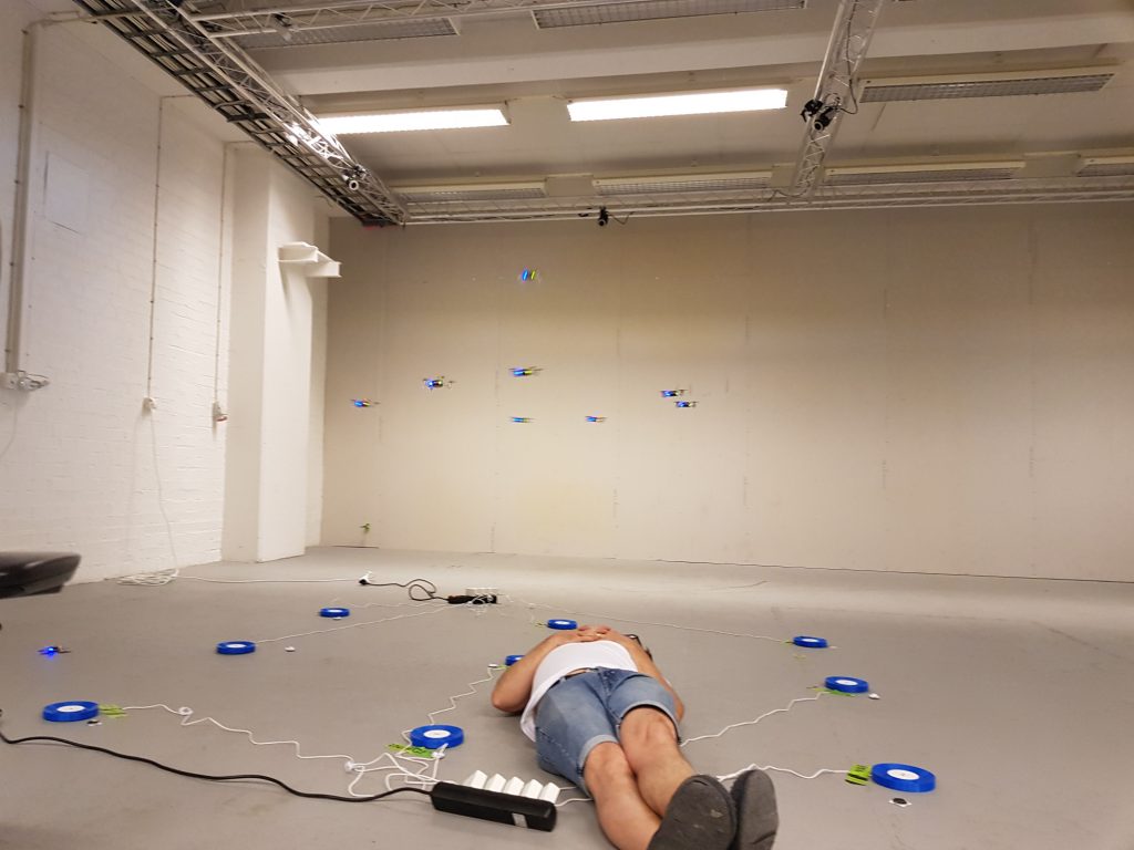
For the last four years of doing my PhD at the TU Delft and the MAVlab, we were determined to figure out how to make a swarm/group of tiny quadcopters fly through and explore an unknown indoor environment. This was not easy, as many of the sub-challenges that needed to be solved first. However, we are happy to say that we were able to show a proof-of-concept in the latest Science Robotics issue! Here you can see the press release from the TU Delft for general information about the project.
Since we used the Crazyflie 2.0 to achieve this result, this blog-post we wanted to mostly highlight the technical side of the research, of the achievements and the challenges we had to face. Moreover, we will also explain the updated code which uses the new features of the Crazyflie Firmware as explained in the previous blogpost.
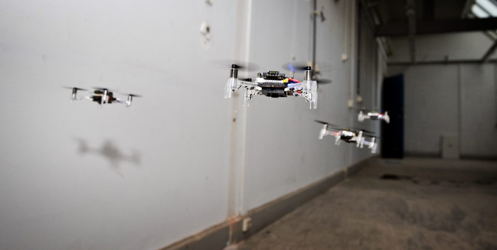
A swarm of drones exploring the environment, avoiding obstacles and each other. (Guus Schoonewille, TU Delft)
Hardware
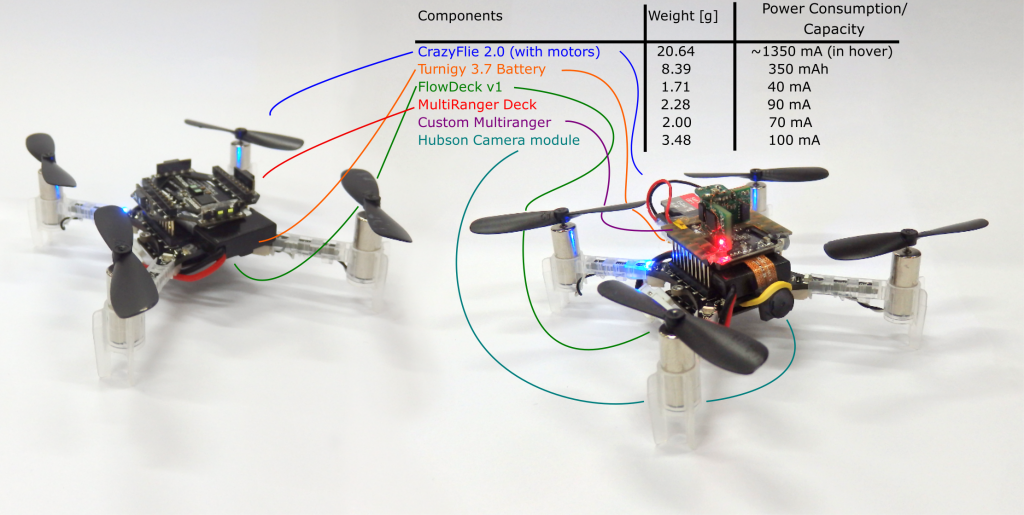
In the paper, we presented a technique called Swarm Gradient Bug Algorithm (SGBA), which borrows (as the name suggests) navigational elements from the path planning technique called ‘Bug Algorithms’ (see this paper for an overview). The basic principle is that SGBA is a state-machine with several simple behavior presets such as ‘going to the goal’, ‘wall-following’ and ‘avoiding other Crazyflies’. Here in the bottom you can see all the modules were used. For the main experiments (on the left), the Crazyflie 2.0’s were equipped with the Multiranger and the Flowdeck (here we used the Flow deck v1). On the right you see the Crazyflies used for the application experiment, were we made an custom Multiranger deck (with four VL53L0x‘s) and a Hubsan Camera module. For both we used the Turnigy nanotech 300 mAh (1S 45-90C) LiPo battery, to increase the flight time to 7.5 min.
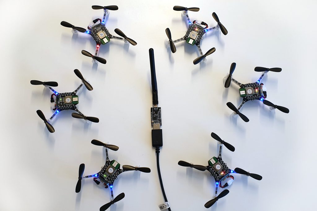
With this, we were able to have 6 Crazyflies explore an empty office floor in the faculty building of Aerospace engineering. They started out in the middle of the test environment and flew all in different preferred directions which they upheld by their internal estimated yaw angle. With the multi-rangers, they managed to detect walls in their, and followed its border until the way was clear again to follow their preferred direction. Based on their local odometry measurements with the flowdeck, the Crazyflies detected if they were flying in a loop, in order to get out of rooms or other situations.
A little before half way of their battery life, they would try to get back to their initial position, which they did by measuring the Received Signal Strength Intensity of the Crazyradio PA home beacon, which was located at their initial starting position. During wall-following, they measured the gradient of the RSSI, to determine in which directions it increases or decreases, to estimate the angle back the goal.
While they were navigating, they were also communicating with each-other by means of broadcasting messages. Based on those measurements of RSSI, they could sense other Crazyflies approaching, which they first of all used for collision avoidance (by letting the low priority CFs move out of the way of the high priority CFs). Second of all, during the initial exploration phase, they communicated their preferred direction as well, so that one of them can change its exploration behavior to not conflict with the other. This way, we tried to maximize the explored area by the Crazyflies.
One of those experiments with 6 Crazyflies can be seen in this video for better understanding:
We also showed an application experiment where 4 crazyflies with the camera modules searched for 2 dummies in the same environment.
Challenges
In order to get the results presented above, there were many challenges to overcome during the development phase. Here is a list that explains a couple of the elements that needed to work flawlessly:
Single CF robustness: We used the Flowdeck v1, for the ‘deadlock’ detection and the basic velocity control, which was challenging in the testing environment because of low lighting conditions and texture. Therefore the Crazyflies were flying at 0.5 meters in order to ensure robustness. The wall-following was performed solely using the Multiranger. This was tested out in many situations and was able to handle a lot of type of obstacles without any problem. However the limited FOV of the laser range finder can not detect all types of obstacles, for instance thin ones or irregular ones such as plants. Luckily these were not encountered in the environment the Crazyflies flew in, but to increase robustness, we will need to consider adding a camera to the navigational drive as well.
Communication base-station. SGBA by essence only needs one base-station Crazyradio PA, since all the behavior is completely on board. However, in order to show results in the paper, it was necessary for the CF to communicate information back, like odometry, state and such. As this was a two way communication (CFs needed RSSI to get back) each Crazyflie needed 1 base-station. Also, they all needed to be on different channels to avoid package collisions and RSSI accumulation.
Communication Peer to Peer. At development time, P2P didn’t exist yet, so we had to implement broadcast communication between the Crazyflies. Since the previous pointer required them to listen on different channels, the NRF had to be configured to send separate broadcast messages on all those channels as well. In order to time this properly, the home beacon had to sync the Crazyflies accordingly by sending out a timer. Even so, the avoidance maneuvers were done very conservatively to try to prevent inter-drone collisions.
Many of the issues, especially the communication challenges, will be solved with the updated code implementation as explained in the next section.
Updated code
The firmware that the Crazyflies used to fly in the experiments showed in the paper, can all be found in this public repository. However, the code is based quite an old version the current Crazyflie firmware, as it was forked almost a year ago. The implementation of the SGBA state machine and the P2P broadcasting were not generic enough to integrate this back to the development cycle, therefore the current code is only suitable for the old Crazyflie 2.0.
Therefore, we developed two major changes in the latest firmware which will make it much easier for me (and other ideas as well we hope!) to implement SGBA and the P2P communication in a way that should be compatible with any version of the firmware (and hardware) from here and on. We implemented SGBA as an app-layer and also handled all the broadcast messaging directly from this layer as well. Please check out this Github repository with this new app layer implementation of SGBA.
Over time the scope of Crazyflie has changed a lot. At first, Crazyflie was “just flying” with the only possible control was attitude (roll, pitch, yaw) and thrust setpoint sent from the Radio. Soon after, autonomous flight was investigated, first by implementing position controller outside Crazyflie and then, over time, moving position control on-board and sending position or trajectory setpoint to the Crazyflie. Now that the Crazyflie has good position control, the next step is to implement autonomous behavior and until now the most practical way is to do this from code running in an external computer. Similarly to what happened in the history of position control (first off-board and now onboard), it needs to be possible implement autonomous behavior in the Crazyflie itself. This blog post is about two newly implemented capabilities that will allow to implement automation in the Crazyflie firmware in an easy and maintainable way, namely the ‘App layer’ and the P2P communication.
App layer
The “App layer” is a term we have been using internally in Bitcraze to describe a set of functionalities that would allow to implement code in the Crazyflie. This includes the infrastructure to compile and maintain external code running in the Crazyflie as well as a set of API to control flight and behavior from C code rather than from radio communication.
Last week we implemented the first step of the App layer: the infrastructure part. It is now possible to build the Crazyflie firmware out-of-tree. This means that it is now possible, from a project, to point to the Crazyflie firmware folder and to compile a firmware from the project folder without touching the Crazyflie firmware folder. Practically it allows to create a git-repos implementing custom firmware code that has Crazyflie firmware as a sub-repos. This makes the maintenance of custom firmware code much easier than maintaining a branch of the Crazflie firmware as previously required.
A second piece that has been implemented is the app entry-point. It allows to start running code by just creating an “appMain()” function. The function will be called from a dedicated FreeRTOS task after the Crazyflie has initialized and started. This should make it much easier to get started.
For an example, we have extracted the multiranger push demo into a standalone git repos. This demonstrate the implementation of autonomous behavior using these new infrastructures.
Peer to Peer communication
The Crazyflie has been used for many research related to swarming, some examples are the crazyswarm project or the work done by Carnegie Mellon University. However, it is now time to turn it up a notch. On the forum and on the Github repository, there has been several request of enabling direct peer to peer communication to the Crazyflies. Now we finally found time to work on it and implement some basic functionality on the NRF and STM side of the firmware.
Currently, it is possible to send and receive a P2P packet in broadcast mode from the STM directly (see how to do this in the documentation). This enables data to be send from one Crazyflie to another with a maximum data size of 60 bytes. We were able to stress-test this with our test rig, by sending broadcast messages in a round-robin-kind of fashion, where the broadcast message was transferred through 10 Crazyflies in 10-20 ms. Even-though the current implementation is for now very minimal, we were able to fix some existing issues in the radiolink framework.
We will not stop there, as we are hoping to implement a communication system similar to how the CTRP protocol has been implemented. We are getting a lot of help by our active community members, so check out this github issue to be up-to-date with the current discussion.
CrazyFlies are great for indoor applications, thanks to their maneuverability and ubiquitous character. Its small size, however, limits sensor quality and compute capability. In our recent work we present source seeking onboard a CrazyFlie by deep reinforcement learning. We show a general methodology for deploying deep neural networks on heavily constrained nano drones, using full 8-bit quantization and input scaling.
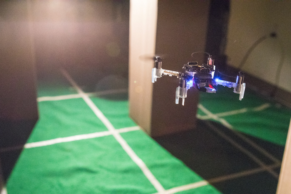
Our fully autonomous light-seeking CrazyFlie
Problem definition
Source seeking can be interesting in a variety of contexts. We focus on light seeking, as seen in nature. Many insects rely on light, either for survival or navigation. Light seeking in aerial robotics has many applications, such as finding the exit out of a dark room.
Our goal is to fully autonomously find a light source, using only the onboard Micro Controller Unit (MCU) and deep reinforcement learning.
Crazyflie configuration
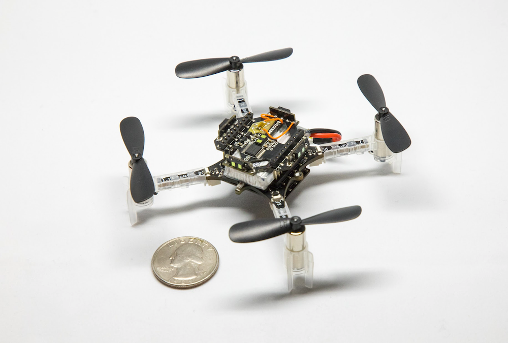
Our fully autonomous nano drone uses several standard and custom sensors. We use the multiranger and flowdeck for position control and obstacle avoidance.
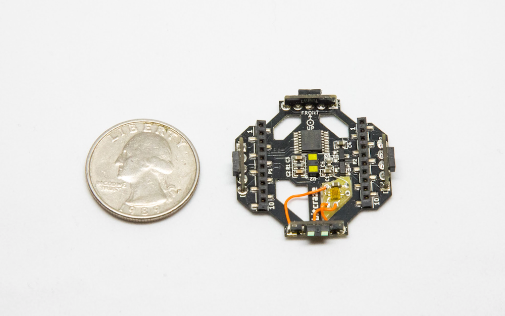
The Multiranger deck with our custom light sensor
We add a custom light sensor, based on the Adafruit TSL2591 sensor. The custom light sensor nicely fits in the multiranger deck, adding little mass and inertia (total vehicle mass is 33 grams).
CrazyFlie 2.1 with multiranger, flowdeck and light sensor
Algorithm
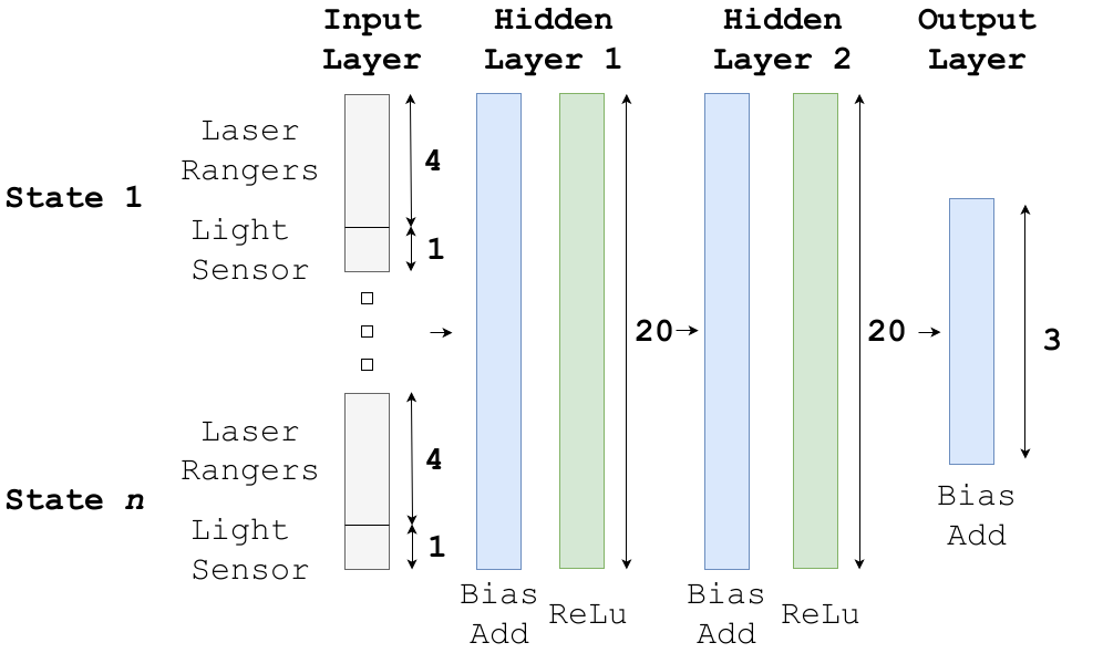
We use a deep reinforcement learning algorithm with a discrete action space. The neural network policy has laser rangers and light readings (current and past values) as input. The neural network tells the drone to rotate left, right or fly forward. We train a neural network with 2 hidden layers of both 20 nodes, featuring bias add and relu activation functions. The input layer is a vector with a length of 20 (4 states), which, compared to images, greatly reduces computational effort.
DQN policy architecture
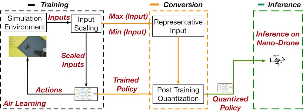
Simulation and conversion
We train our agent in simulation using the Air Learning simulation platform, after which we fully quantize the neural network to 8-bit integers.
To maintain accuracy after quantization, we have come up with quantization innovations. Both input layer and all tensors in the network need to have a pre-defined [min,max] range in float32, to convert to 8-bit integers.
Air Learning pipeline
In the input layer, not all inputs have the same range. That is, a laser ranger can have values from 0 to 5 meters while our light sensor may return a value between 0 and 300 lux. To avoid this issue, we scale all inputs to the same range.
Additionally, the tensors in the network need to have an assigned [min,max] range for quantization. To achieve this, we input a range of representative input into the unquantized model, and read out the values of intermediate layers. With this strategy, we arrive at a 2.9x speed-up compared to float32 inference.
Implementation
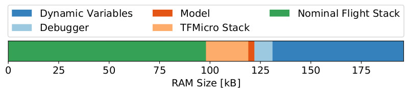
We use Tensorflow Lite to deploy our tensorflow models in C on the CrazyFlie. The TFMicro Stack, together with the actual model, almost completely fill up the available RAM.
RAM utilization on the CrazyFlie 2.1
The total amount of RAM available on the CrazyFlie 2.1 is 196kB, of which only 131kB is available for static allocation at compile time. The Bitcraze software stack uses 98kB of RAM, leaving only 33kB available for our purposes. The TFMicro stack takes up 24kB, thus leaving 9kB for the actual model (e.g., weights, bias terms).
We also analyzed CPU usage, and noticed a high amount of interrupts by the ‘stabilizer’ thread, i.e., the PID controllers. Because of these interrupts, inference of our model takes 46.4 times longer than it would have been without interruption.
Our quantized model is 3kB. If it were an FP32 model, it would have taken 12kB, which would not have fitted in the available memory. We were able to run inference at 4Hz, compared to the estimated 1.4Hz of the same but unquantized model.
In a practical sense, we noticed a decreased level of stability when increasing model size. Occasionally the drone would reboot randomly while flying. Possible causes for this behavior are RAM overflow and task scheduling problems in RTOS. Besides, we observed variation in performance loss after quantization. Some of our trained models would just keep rotating after quantization, while our final model demonstrates robust source seeking behavior. This degree of uncertainty can possibly be avoided using quantization aware training.
Finally, flying in a dark room without a position estimate can be challenging. The PID controllers heavily rely on information provided by the Flow Deck. This information is limited when little light is present while flying over a floor containing little features. To fix this, we added mats with texture on the ground, adding features and enabling stable flight in a dark room.
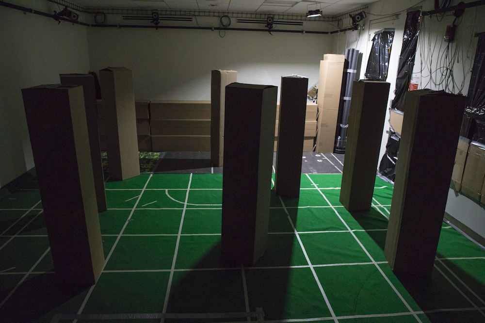
Flight tests
To validate our results in simulation, we created a cluttered environment with a light source. We randomly initialized the drone in the room, and hereby observed a success rate of 80% in a total of 105 flight tests. By varying the environment and initial drone position, we learned more about the inner workings of our algorithm.
Experiment testing environment
We learned that the algorithm performs better with more obstacles, and that a closer initial position improves performance. Generally, source seeking far away from the source seems really hard. Almost no variation in source strength exists between different measurements, and the drone observes mostly noise.
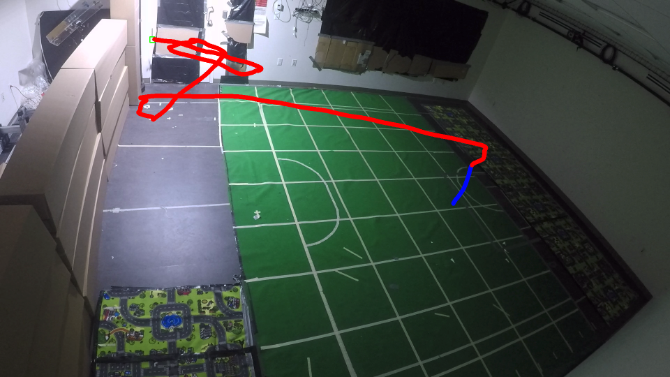
Outlook
With our methodology, we were able to perform fully autonomous source seeking using deep reinforcement learning on a Cortex-M4 MCU. We hope our methodology will be applicable to other TinyML applications where resources are heavily constrained. Developing custom accelerators for a specific workload is time-consuming and expensive, while general purpose MCU’s are cheap and widely available. With our methodology, we unlock new applications for learning algorithms on heavily constrained platforms.
Direct path to source in empty room, blue = take-off
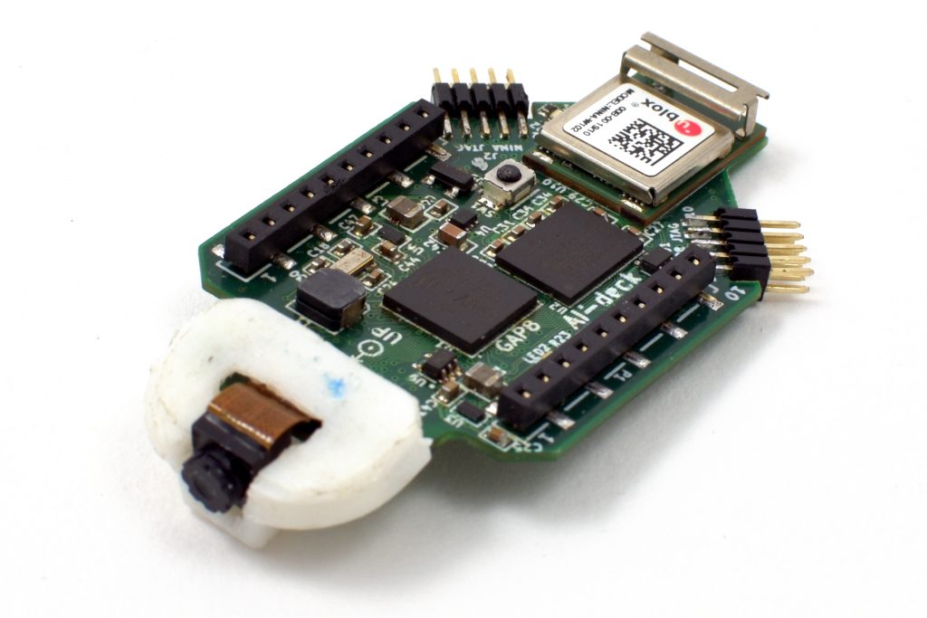
As pointed out in Daniele’s blog post about the PULP-DroNet we are collaborating on a AI-deck built around the new GAP8 RISC-V multi-core MCU. In the blog post you can find all the details around DroNet while here we will talk a bit about the AI-deck hardware. The AI-deck is similar to the PULP-Shield but with some optimizations. One of the HyperFlash memory spots has been removed, the communication interface slimmed down and a ESP32 (NINA module) has been added for WiFi connectivity.
Latest AI-deck prototype
So all together this a pretty good platform to develop low power AI on the edge for a drone.
Features:
GAP8 – Ultra low power 9 core RISC-V MCU
Himax HM01B0 – Ultra low power 320×320 greyscale camera.
512 Mbit HyperFlash and 64 Mbit HyperRAM
ESP32 for WiFi and more (NINA-W102)
2 x JTAG for GAP8 and ESP32
Currently we are doing the final testing of the hardware and hopefully we will launch production in the end of October. If production goes according to plan we hope we can offer it as an early access product just before X-mas. Make sure to come back and check the blog for more information about the progress as well as pricing.
We are happy to announce that we have made new official releases of a number of our software components. The name of the release is 2019.09 and we have outlined the main changes below.
Crazyflie/Roadrunner firmware
Added support for the Crazyflie Bolt
Improved support for external positioning systems
Basic support for the Lighthouse positioning system
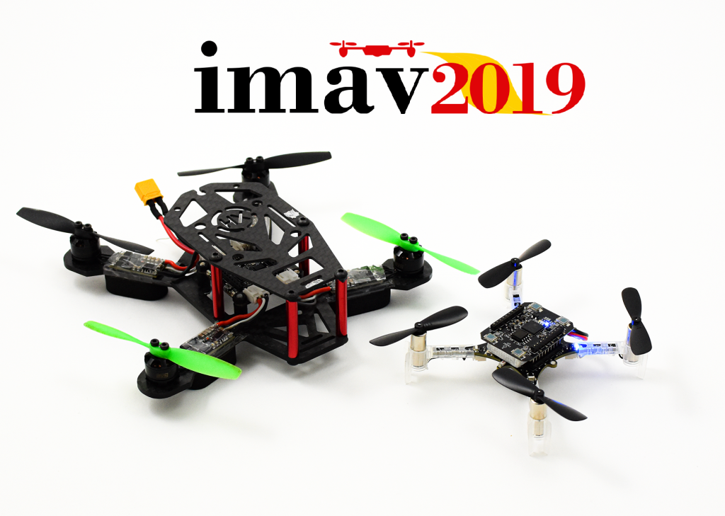
The Crazyflie Bolt and the Crazyflie 2.1 with the lighthouse deck are coming to Madrid!
Only one week away until the start of the big Bitcraze Conference frenzy, with the first stop… Madrid! We will visit the Micro Air Vehicle Competition and Conference, which is a robotics event that is more specialized in (as the name implies) MAVs! So it should be right up our alley. This is the first time that we attend as Bitcraze, although the writer of this blog post has experienced fun times at the conference and the competition as a participant with her previous lab, the MAVlab.
The IMAV has been around for almost 12 years, starting in Toulouse, France in 2007. Although it initially mostly was held in various places in Europe, in 2016 into a more worldwide phenomenon by making it’s tribute in Beijing, China and Melbourne, Australia in 2018. It hosts a conference to which researchers can send their work in anything related to MAVs, from autonomous navigation, state estimation and design.
IMAV is mostly know for hosting big indoor and outdoor competitions for MAVs. The outdoor competitions can range from survey tasks to finding a hidden person or object. This year the focus will be on the delivery of packages from one place to another. The judges will look at how many packages that can be safely delivered and if the drone is able to detect certain objects in the outdoor environment. The indoor competition is oriented around the application of MAVs in a warehouse. They should be able to take off autonomously, monitor boxes in shelves and make an innovatory, and pickup packages to release them in their designated location. 40 teams of 28 universities will show their awesome implementation in these difficult tasks.
We will have a booth at the main company fair at the conference and indoor competition, and will also be present at the outdoor competition day as well. We will bring the lighthouse positioning system and show the awesome swarming demo we developed. Also we want to bring the new Crazyflie Bolt with us, which we are sure of that the regular IMAV crew will love. If you are at the IMAV between the 30th of September to the 4th of October, come by and say hello!
We have referred to Fun Fridays in a number of posts in this blog, but recently realized that we never described what it is about. Hopefully that will be rectified in this post.
The concept is simple: on Fridays we do what ever we want to, as long as it is fun, interesting and (at least remotely) connected to Bitcraze. It might be trying out a new technology, play with a new sensor, create new functionality, design a prototype board or similar. Our belief is that playing is key to being creative and that creativity is beneficial to the employees as well as to the company.
There are many other companies that have similar concepts, though most of them might not go as far as reserving 20% of the time for it. For us this was a simple choice since we’re all really passionate about technology and like to explore new things.
We’ve tried to implement this in previous work environments and also talked to other companies about it. Most of the time it comes down to two things, trust and money. The concern that employees will not do useful things and this will waste company resources (i.e money). For us this isn’t really an issue. First of all we work in a way where everyone is involved and takes responsibility for the company, so we trust everyone on the team. Secondly the idea behind Bitcraze is to create a workplace where we want to work. The idea has never been to optimize on profit but instead create a sustainable company that shares the values and direction of the team.
Even though we do not prioritize higher profits, it turns out that time when employees can make their own choices are very good from a business point of view as well. It has been said that 3M has a similar concept where they invest 15% of the time into “free” projects, and that 85% of the revenue today comes from these projects!
Looking back it has also been a good deal for Bitcraze, a lot of our products (actually most of them) and internal systems have been started on Fun Fridays. A few examples are the LPS, the Lighthouse and the Multiranger deck as well as the Bolt. There is also a (large) number of prototypes in our drawers that never made it into products, not to mention the happiness it has created!