Working at Bitcraze means designing electronics as well as writing software for it, but there is also a lot of other things going-on and managing servers is one of them.
Originally, in 2011 we had a virtual server in the cloud (a VPS like it was called back then). We carefully setup and configured this server and we maintained it over the years. This was easy and served us well but it was also very ‘manual’: any updates where done on the production machine directly and we where doing all changes directly in the production machine.
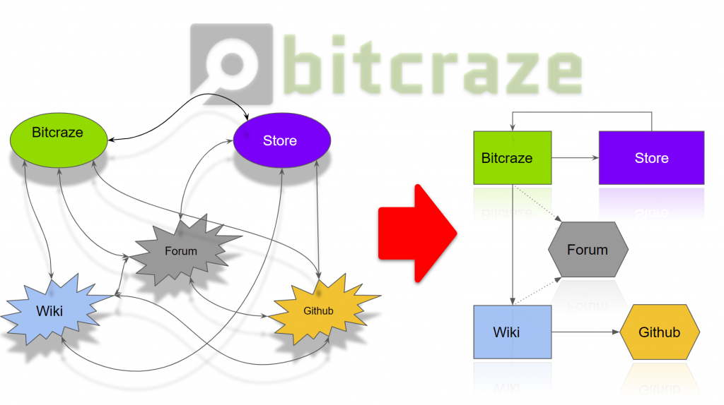
In 2015, when Kristoffer joined Bitcraze, he revamped completly the server setup. Suddenly we had not only one server but two, one production and one staging. And all servers running on these machines where running in docker containers. This means that the servers where nothing more than a well configured machine to run docker, and all important software and configuration are in docker images and are launched using docker-compose. This is the architecture we are still using today, a great description was written by Kristoffer in a previous blog post.
The docker architecture has worked well but we still have one major problem, we still have servers to take care of. They are still configured manually, needs to be kept up to date and happy at all time. We have been wanting to get rid of these servers and “just” run our containers.
Now enter Kubernetes. Kubernetes is a container Orchestrator originally made by Google that abstracts the servers and allows to run containers independently of handling servers. We had heard of Kubernetes back when we started working with Docker but deemed it overkill: we did not want to setup and handle a cluster of server by ourselves and back then it was not clear that how long Kubernetes would be around. Over time though Kubernetes has had support by all major cloud providers and there is managed offers that would allow us to not handle any servers ourselves.
We are not there yet, but we have been working over the summer at converting our infrastructure to Kubernetes and we are very close to deployment. One of the main parts is our internal Jenkins build server that currently build and deploy services by ssh-in into servers. With Kubernetes this deployment phase will be much simpler and will allow us to update the website without downtime, this is a welcome functionality now that the documentation is moved from the wiki to the main website.
With lightweight Kubernetes distributions like K3S there is also an opportunity to run containers in more domains. For instance we have been talking about making automated hardware system test-bench for a while to test every commit against the real hardware. With K3S and a couple of raspberry-pi that could be achieved quite easily. This is a subject for future fun Fridays though … :-).