Who knew propellers would be that hard? Already from the very beginning with the Crazyflie 1.0, we had problems with very unbalanced propellers resulting in reduced flight performance. The fix at that time was to manually test and sort out the bad propellers. This worked well until the manufacturer’s injection mould got too worn down and we had to reject a lot of propellers. The manufacturer didn’t want to continue selling us the propellers unless we accepted them all. The hunt for a new manufacturer begun and after trying several, we finally, just in time for the Crazyflie 2.1, found one that could deliver well balanced propellers.
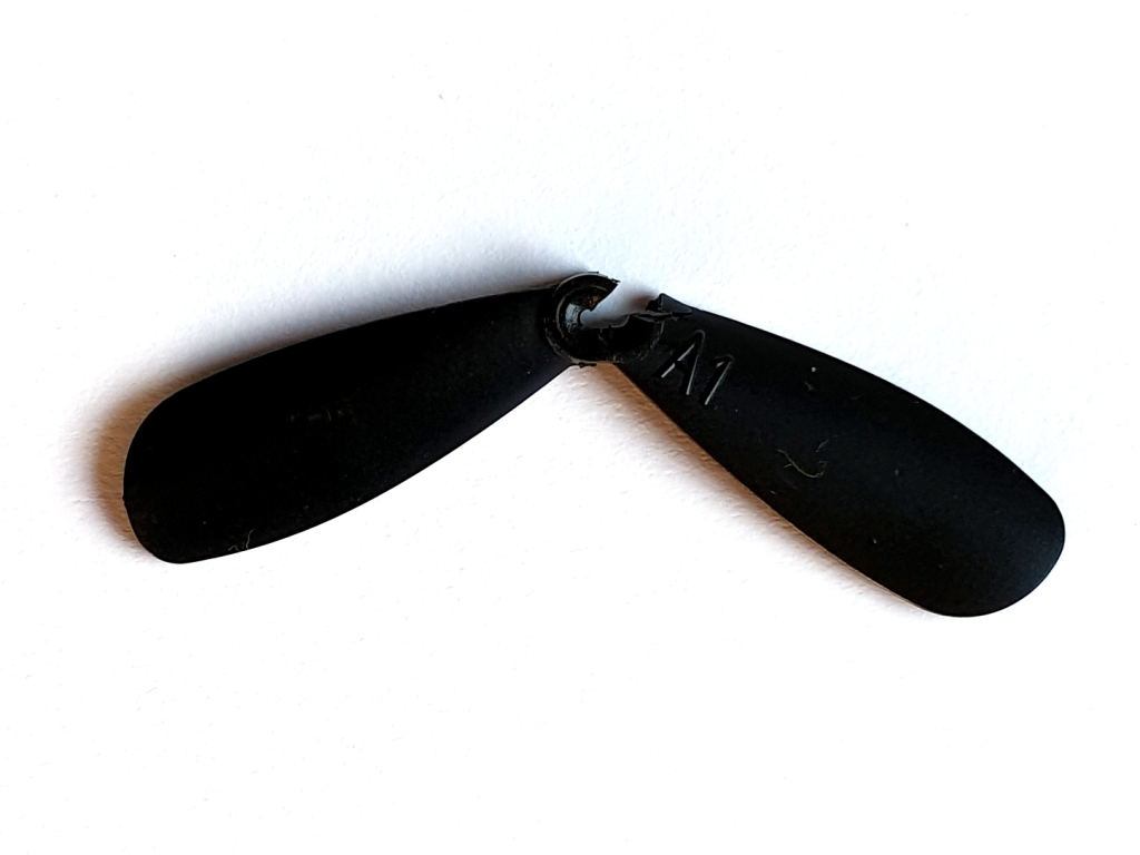
That could have been the end of a happy story but recently we found out that the new propellers tend to break too easily. The root cause seems to be that the center hole is too tight, causing tension in the plastic which makes it more fragile and prone to break.
Typically broken propeller
We don’t fully understand when this started but it looks like it was not that frequent in the beginning when the Crazyflie 2.1 was released and that it has increased from the batch manufactured in the end of July 2019. We don’t have data on how many propellers are bad but our estimation is around 20-40% and it is booth CW and CCW propellers. It also includes the spare part bundles manufactured in the second half of 2019.
Currently out main focus is to fix this propeller manufacturing issue. As soon as we have done so, we will lunch some form of replacement propeller program so that those of you that have gotten many bad propellers can get new ones for free. We don’t have any time estimate right now, and due to the world covid-19 crisis we have a feeling it can take a while. We are very sorry about this!
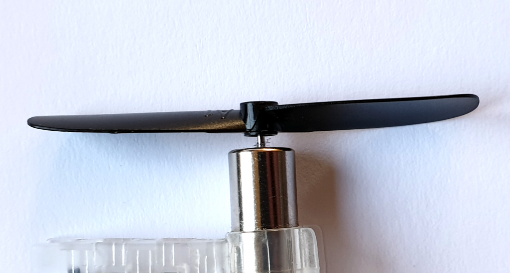
Insert propeller so it sits firmly, but not further
Workaround
There is an easy, but not ideal, workaround for this and that is to not push the propeller all the way down on the shaft. Instead stop when force is getting high and it holds the propeller in place. This will prevent the tension in the propeller to become big enough to break.
For those that have ordered after the 16th of March we have fixed the propellers by drilling the center hole slightly larger. This solves the problem for those units until we have fixed the root cause at the manufacturer.
Considering the recent pandemic and the global situation, we at Bitcraze had to think about what will be our next step. Even though everyday life in Sweden is still going on, and all of us are in good health, we know there are a lot of you that are impacted by the CoronaVirus. We wanted to take responsibility for each other, the Swedish health care system, and the rest of our community by actively minimizing our social interactions. The best we can do right now is contributing to stop the disease and preserve our health.
So for the time being, we all will be working from home. Shipping of orders will be a bit slower (twice every week instead of the current four times), but other than that we hope to still be available as usual. Forums posts, sales and other daily tasks will go on as usual. Hopefully you won’t see the difference! We will still work on providing you the best flying experience we can.
With the new situation comes new challenges for the team, that we’re trying to make the best of. First of all, we will test a whole new way of working – together but apart! And we hope this will also give us the opportunity to work on some things that otherwise are a little bit left out… But you’ll have to be a little patient to discover these!
If you’re stuck at home and are getting bored, why not fly your Crazyflie and send us a video? We’ll post regularly those on our social media to fight against the current feeling of gloom and potential loneliness associated with confinement!
Our thoughts and well-wishes are with everyone affected by the situation.
This is it. The end of my internship. It feels strange to leave this unique office in a place called Malmö. My time spent here was more than just doing an assignment as part of a MSc. degree with the objective that I would gain working experience and contribute to a company.
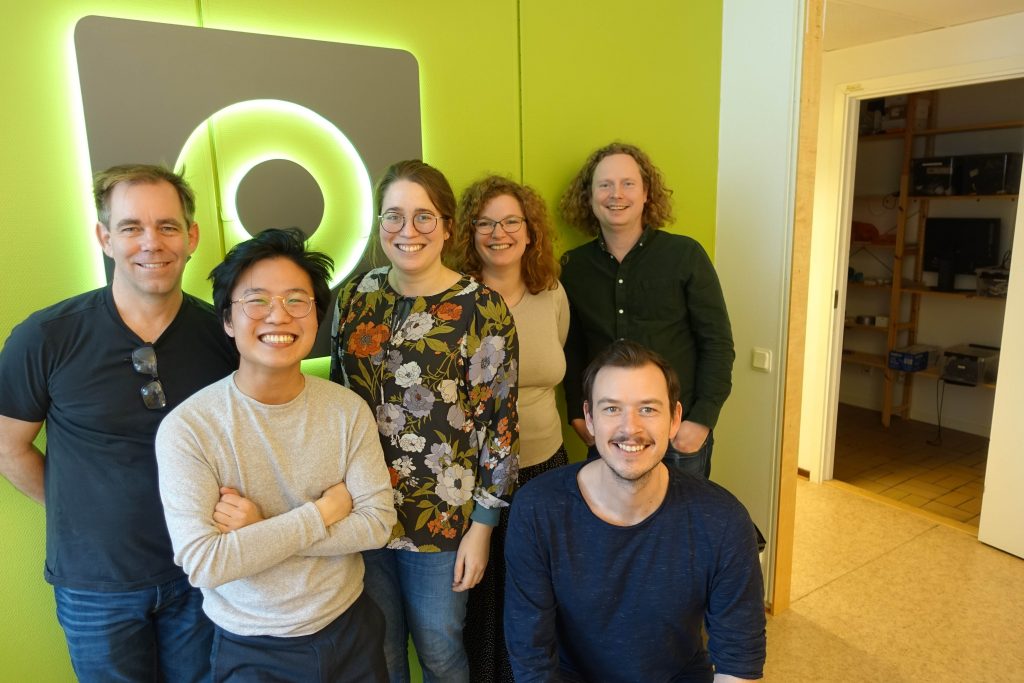
My last day at the office of Bitcraze, Arnaud was already on parental leave
My time here gave me so much more. I have learned here a healthy way of thinking and problem solving which is part of the unique Bitcraze company culture. Next to that, it felt more like working with friends than just working with colleagues. Going to the office is a delight, as there is always humor, openness and honesty. I got to know everyone and enjoy the French, Swedish and Dutch-American hospitality and culture.
At this point you might think that I only have been drinking coffee and made sure that coffee in the office was not below level. Luckily that was not the case. I had the privilege to be the first user for a new deck. This deck has been in development for quite some time now and has been glossed over in some earlier blog posts. It is the yet to-be-released AI-Deck! At the moment the early-access AI-Decks are a delayed due to the COVID-19 virus. Bitcraze will update you on the blog when they know more.
My task within Bitcraze, in more detail, was to improve user friendliness of the AI-Deck by providing a framework for future users and at the same time to explore user friendliness of the whole ecosystem around the AI-Deck for an engineering student with beginner experience in embedded programming (e.g. me).
At the verge of giving the Crazyflie some AI capabilities, while being micromanaged.
So my mission began. A logical step was to see if the convolutional neural network from the PULP-DroNet project would run on the AI-Deck and fly with the Crazyflie, as the AI-Deck is an evolution of the PULP-Shield developed for this project. More information about this can be found here.
Unfortunately, this was not an easy feat as the PULP-DroNet project is using the pure version of the PULP SDK and an outdated autotiler. While the development partner for the AI-Deck, Greenwaves Technologies, uses the PULP SDK as a base with added functionalities in their SDK, which made it divert from the SDK used in the PULP-DroNet project.
Though, I was able to run the convolutional neural network in a simulated environment and compare this to the original DroNet that was implemented using Python and a Bebop. It was interesting to find out that the convolutional neural network of PULP-DroNet was behaving differently than the original DroNet in Python. There can be many explanations for this, but the main hypothesis is that this is caused by quantizing the network of PULP-DroNet from 32-bit floating point to 16-bit fixed point. In addition, the aforementioned network is trained on a larger dataset which included data created by a Himax camera.
A single Crazyflie obtained self-awareness and spun up a swarm of Crazyflies to gain world domination
While porting PULP-DroNet to the AI-Deck should be possible, the obstacles found along the way made it too troublesome and out of scope for my internship. So I moved on with the main objective, making a framework/example for the AI-Deck using the SDK provided by Greenwaves Technologies, which is called the GAP8 SDK. It contains a set of tools that should make the use of the AI-Deck easier, namely the NNTool and Autotiler tool. These tools make sure that you can automate the conversion of your neural network that is designed and trained in Python (Tensorflow and Keras) to a neural network code that can utilize the GAP8 functionalities.
My internship came to an end before I could overcome the last hurdle for a working example. To still bring this example to you, I have committed the doc/code I wrote and handed over the knowledge that I have accumulated throughout my internship when working with the AI-Deck and its environment to the capable minds of Kimberly and Tobias.
Along the way I have learned a lot about embedded programming and being a first product user. In addition with embedded programming and programming in general comes a different mindset than a conventional planning and deadline fixed mindset you get from university. With these valuable lessons in mind, I will be heading back to the TU Delft to start with my master thesis in either reinforcement learning for aircrafts or dense optical flow nets for quadcopters. Thank you Bitcraze for your time, experience and hospitality!
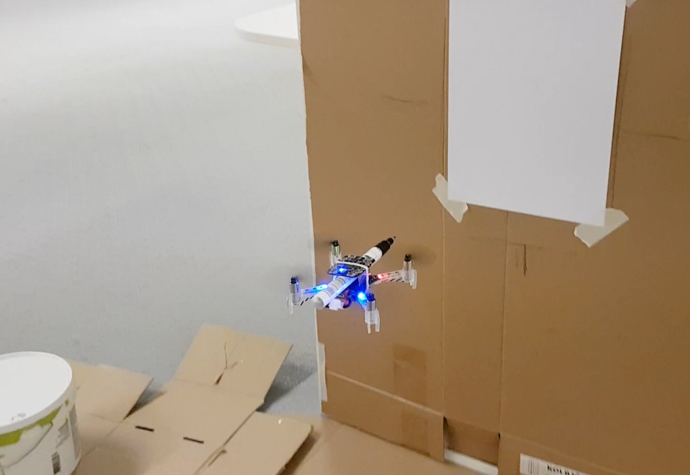
There has been some work done earlier to use the Crazyflie for generating images, for instance the dot-drawing by Paul Kry and light painting. I wanted to see if it is possible to put a brush or pen on a Crazyflie and use it to draw lines on a paper. I decided to use a fun Friday to try it out. The idea is simple: mount a pen on the Crazyflie, put a paper on a wall, write a script to draw a figure, fly!
The setup
The first thing I looked into was to investigate if a Crazyflie can fly with a brush or pen mounted on it. I wanted to keep the weight down and my initial approach was to use a cotton swab (0.6 g) dipped in paint. I found one that was long enough to extend in front of the propellers and I mounted it by squeezing it between the battery and the PCB. Flying was no problem with such low extra weight.
For positioning I decided to use the Lighthouse system. It is very accurate, simple to use and the easiest way to get started. I mounted a piece of cardboard in the YZ-plane of our lighthouse coordinate system, where I could attach a drawing paper. The idea of setting up the drawing surface parallell to the YZ-plane was to make the scripting easier. I (of course) used the Crazyflie and lighthouse system to measure that the cardboard was mounted at the right position.
Finally I wrote a simple python script that utilized the high level commander to move towards the drawing surface and yawing at the right position to draw a stroke on the paper. It sort of worked, but the cotton swab has to be “refilled” before each stroke which took a lot of time, and the results were a bit random.
I decided to try out a pen instead. The upside is that it does not require refill, on the other hand it is much heavier which makes the Crazyflie a bit sluggish when flying. I mounted the pen on the top side of the PCB, squeezed under the Lighthouse deck, and moved the battery to under the Crazyflie to distribute the weight.
Initial tests – both cotton swab and pen
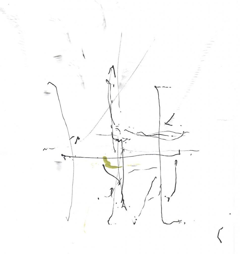
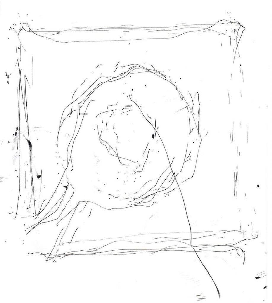
The script was updated to draw the outline of the Bitcraze logo. I had a couple of variations where I tried to draw the full outline in one long stroke, as separate strokes, going up or going down and some other flavours.
So was it successful? Currently the Crazyflie is not a new Picasso, but the painting skills could maybe be improved with some more work. I think the main problems were:
the pen is too heavy and requires too much force on the paper
the controller cannot handle the situation in a good way. In essence I set the set point a few millimeters “into” the paper to push the pen against the surface which seems to be confusing as the controller can not reach the set point.
Flying that close to the drawing surface creates an air flow that disturbs the flight.
We are happy to announce that we have gotten Crazyflie 2 to fly autonomously using the Lighthouse deck and Lighthouse V2 base-stations. This was a very requested features, and while this is not stable and ready to use yet, it is a great milestone toward Lighthouse V2 support.
There exists two incompatible versions of the Lighthouse positioning system. Version 1 was released with the original HTC Vive VR system. In this system base-station are using two rotating laser beam that sweeps the room, one horizontal and one vertical, and an omnidirectional synchronization flash to allow IR light receiver to be located in the room. One limitation of this version is that up to two base-station can be used and no more, this is mainly due to the fact that beam identification is done using a TDMA scheme: base stations switch-on their laser in a dedicated time-slot one after each-other and adding more time slots for more base-stations will greatly reduce the update rate of the system.
Lighthouse V2, was released with the HTC Vive PRO headset and is also used by the Valve Index. The big change is that laser sweeps now carries modulated data and that there is only one rotor with two angled slit instead of the two rotors for V1. The V2 sweep data is described as ‘Sync on beam’ and contains timing information of how long it has been since the synchronization event (ie. when the rotor crossed 0 degree). The sweep data also allows to identify the base-station that has transmitted the sweep. This removes the need for an omni-directional synchronization pulse and allows more than two base-station to operate at the same time in the same space, since their sweeps can now be identified and timed.
The lighthouse V2 system is very elegant and scalable. However, actually decoding the signal from the sweeps has taken a lot of time since it is not documented and we needed to find-out what the encoding actually was. There has been effort on the internet to understand how the system worked, the most useful one is this github ticket that goes from raw data acquisition to fully unlocking the beam encoding.
I have been working on-and-off for a long time on making an FPGA design for the lighthouse deck to acquire and decode Lighthouse V2. The main blocking point until now was that I had not been able to reliably acquire useful signal from the system in order to allow real-time decoding on the Crazyflie. Added to that, there was some inconsistency between what we though the system was doing and what we could gather from the base-stations debug console. Recently though, the last piece of the puzzle, was to discover that the beam encoding was not Manchester, as we though, but Bi-phase mark code FM1 (BMC). Once this decoding was used everything made sense and worked.
Added to that, I started using SpinalHDL instead of raw Verilog to write the FPGA design which allows for much quicker iteration, much less frustration, and it also allowed me to easily make the design multi-clock which is required to decode the BMC signal: the beam decoder runs at 48MHz, and the rest of the system works at 24MHz. This design is required since the FPGA we use in the lighthouse deck is not fast enough to run everything at 48MHz.
The result, is a new FPGA firmware for the lighthouse deck that receives, identify and decode Lighthouse V2 sweep signal and send them over to the Crazyflie. The Crazyflie still has a little pulse packing to do (putting together pulses from a single sweep received on multiple sensors) and then can use pulse timing information to calculate azimuth and elevation at which the base-station sees the Crazyflie. This information is the same as the one we get from Lighthouse V1 and so the same algorithm can be used to calculate the Crazyflie position.
I hacked a proof of concept was this last fun Friday and it flies!
If anyone is curious the code for this demo has been uploaded as an out-of-tree driver and the code for the FPGA parts is already in the lighthouse-fpga project. The current Crazyflie code is too incomplete to be usable, but it is a nice starting point if anyone wants to play with Lighthouse V2 and the Crazyflie right away ;-).
As a side note, the Bitcraze team will shrink temporary as I, Arnaud, will go in parental leave until mid-August. I look forward to this new adventure and I trust the lighthouse V2 development and the forum will be in good hands in my absence.
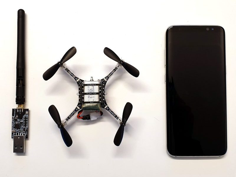
The Crazyflie supports wireless communication using both the Crazyradio PA and BLE (Bluetooth Low Energy https://en.wikipedia.org/wiki/Bluetooth_Low_Energy). BLE is used with the mobile phone apps while Crazyradio PA usually is used together with a PC.
The lower levels of the radio communication in the Crazyflie is handled by the nRF51 that is capable of handling both types of communication. When using the Crazyradio we are using the manufacturers, Nordic Semiconductor, proprietary Enhances ShockBurst protocol (ESB) which makes it simple to send packages, up to 32 bytes, between each other. When communicating over BLE we are using Nordic Semis S110 SoftDevice which is a BLE stack developed by Nordic Semi to simplify implementation.
When we designed the first Crazyflie, the Crazyflie 1.0/Nano, we choose to use the nRF24L01+ that uses the ESB protocol because of simplicity, good range and low latency. Then came the Crazyflie 2.0 and we wanted BLE for mobile client support. Luckily Nordic released the nRF51 which could handle both. However there is a small drawback, both protocols can’t run concurrently and has to be interleaved. For BLE this has never been any problem as this protocol has the priority, but for ESB it means that when BLE is running there will be a small amount of packet loss.
The CRTP protocol we developed that runs on top of the ESB, handles the packet loss fairly well but as more and more Crazyflies are added we have been seeing communication issues. So last week we dived in to this problem and after some digging we understood that BLE was one of the problems. Therefor we added a switch which disables BLE as soon as a ESB packet is received. This improved the ESB connection and it now seems more stable. If you have the possibility we suggest you to get the latest from the crazyflie2-nrf-firmware master branch, try it out and give us feedback.
This change will hopefully provide more stable communication between the Crazyradio PA and the Crazyflie. From a functionality point of view, most users will not see any difference, but we would like to point out that if you have communicated with your crazyflie using the Crazyradio PA, it will not be possible to connect with a mobile phone until the Crazyflie has been re-booted. Note that a simple radio scan with the python client has the same effect and disables BLE.
When there is a possibility to name a release with only two’s and zero’s one has to take that opportunity right! Adding to that, it was about time to make a new release, and there is actually another reason. As we wrote about in the “What’s up 2020” blog post, it’s time to look back, finish up and make things more stable. This includes improving documentation, more examples/tutorials etc. With this release we create a good baseline to start this work from.
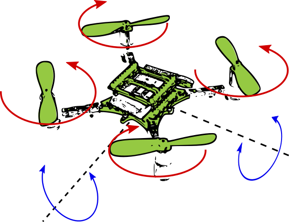
Two weeks ago, we had a blogpost about the state estimators that are available within the Crazyflie. So once the Crazyflie knows where it is, it would need to be determined where it wants to go, by means of the high level commander (implemented as part of the crazyswarm project) or set-points given by CFclient or directly from scripts using Crazyflie python lib. But exactly how would the crazyflie get to those desired positions in the first place? The differences between the current state estimates and the desired state, will need to be transformed to inputs given to the motors. Unfortunately, quadrotors like the Crazyflie do not have easy dynamics to maintain, so if you want to learn more, see this blogpost to read more about it!
Controlling the Crazyflie
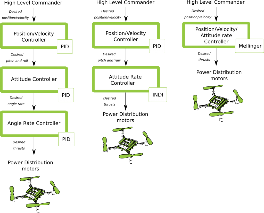
So in order use the thrust of the motors in an useful way to get the Crazyflie to do what you want to do, there are several controllers to consider, which you can see on this quick overview here underneath. It shows the different control paths that can be taken from the high level commander all the way to the power distribution of the motors. Bear in mind that these are still simple representations and that the actual implementation is of course a bit more complicated, but at least it will give you a rough idea of which paths are possible to pursue.
Possible controller pathways
PID Controller
So the default settings in the Crazyflie firmware is the proportional integral derivative (PID) control for all desired state aspects. So the High Level Commander (HLC) will send desired position set-points to the PID position controller (which used to be done off-board, so outside of the Crazyflie firmware before this blogpost). These result in desired pitch and roll angles, which are sent directly to the attitude PID controller. These determine the desired angle rates which is send to the angle rate controller (which is… you guessed… also a PID controller). This is also called Cascaded PID controller. That results in the desired thrusts for the roll pitch yaw and height that will be handled by the power distribution by the motors. (Note that height is mostly handled by the position controller)
INDI Controller
So the Incremental Nonlinear Dynamic Inversion (INDI) controller is an controller that immediately deal with the angle rates to determine the trust. This is a very new addition to the Crazyflie firmware by one of our community members and is based on the implementation of this paper. Currently, the position control is still handled by the same PID controller mentioned in the last paragraph, Nevertheless for handling the angles, it should be faster than the attitude and rate PID controller combined. We have not yet fully tested this out but if you do, let us know how you like it on the Bitcraze forum!
Mellinger Controller
As part of the Crazyswarm project, the controller designed by Daniel Mellinger has been implemented in the Crazyflie firmware as well. Please see this paper about the details of the Mellinger controller. It is a sort of “all in one”: based on the desired position and velocity vectors towards those position, it will calculate right away what the desired thrusts are that need to be distributed to all the motors. This results in a much smoother controlled trajectory of the high level commander and therefore advised to use when the Crazyflie has a precise position estimate (lighthouse and mocap). However, as it is so aggressive, any position estimate of a lesser quality (flowdeck or LPS) will not be sufficient for this controller. See some examples of mellinger controlled flights here and here.
Let us know what you think!
So do you have experience working with these controllers or want to know more about them, please drop us a message on the forum! We are currently working on stabilization and documentation of multiple aspects of the Crazyflie and the controllers is one of them, so we are really interested what your experiences are!
My name is Barbara, and I’m really proud to say I’m the new member of Bitcraze. As of now, I will be dealing with everything non-technical, so that the great minds here can focus on creating more of their amazing products!
If you want to know a little more about me, I should start by the beginning. I come from France originally, but have moved a lot over the years. From my early childhood in Tunisia to my semester abroad in Canada, I never really settled down… Until I came to Sweden, a little over 5 years ago. After having lived in Paris for some time, Malmö was a much needed breath of fresh air. In France I worked on a lot of different fields: receptionist, assistant, salesperson, teacher’s assistant, even as an actress. Those different experiences broadened my horizon and taught me a lot. Most of all, I learned to follow my passions: helping people, singing, and generally loving what I’m doing. My last assignment included community management and content creation in a video game company, but I’m happy to use every bit of my 5 years experience as an administrative assistant to be the office wizard here at Bitcraze.
When I’m not taking care of my family or working, I keep on following my passions. I could talk hours about movies or books (especially about Terry Pratchett books, or musicals, my favorite type of movies!). I took up knitting a year ago and can’t put my needles down now. And I consider myself a real geek. Video-games, movies, comics, I even learned some programming over the years (even tough I can’t compare with the other team members!). My greatest challenge last year was to build my own PC, and I have to say that I managed it with flying colours. Another way I past the time (while making everyone happy) is by baking, and every time a new batch of cookies gets out of the oven, I feel the weight of the family tradition: my grandfather was a french pastry cook, and I proudly follow his footsteps (and recipes!).
I’m really happy to join the Bitcraze team and excited about the future. I hope I’ll learn a lot from working with Arnaud, Kristoffer, Kimberly, Marcus and Tobias. My girly-geek side can’t stop jumping with excitement at working in such an impressive and stimulating environment.
Fosdem 2020
Arnaud is going to Fosdem this weekend, check out his forum post and say hi if you are there.
How does a Crazyflie manage to fly and stay in the air in the first place? Many of us tend to take this for granted as much research tend to happen on the application level. Although we try to make the low level elements of flight as stable as possible, it might happen that whatever you are trying to implement on the application level actually effects the Crazyflie on the low level controls and estimation. We therefore would like to focus a little bit on the inner-workings of the autopilot of the Crazyflie, starting with state estimation. The state estimation is part of the stabilizer loop in the Crazyflie, an overview of is was made in a previous blog post.
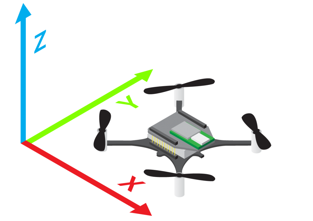
State estimation is really important in quadrotors (and robotics in general). The Crazyflie needs to first of all know in which angles it is at (roll, pitch, yaw). If it would be flying at a few degrees slanted in roll, the crazyflie would accelerate into that direction. Therefore the controller need to know an good estimate of current angles’ state and compensate for it. For a step higher in autonomy, a good position estimate becomes important too, since you would like it to move reliably from A to B.
There are two types of state estimators in the crazyflie firmware, namely a Complementary Filter and an Extended Kalman Filter.
Complementary Filter
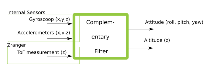
The complementary filter is consider a very lightweight and efficient filter which in general only uses the IMU input of the gyroscope (angle rate) and the accelerator. The estimator has been extended to also include input of the ToF distance measurement of the Zranger deck. The estimated output is the Crazyflie’s attitude (roll, pitch, yaw) and its altitude (in the z direction). These values can be used by the controller and are meant to be used for manual control. If you are curious how this code is implemented exactly, we encourage you to checkout the firmware in estimator_complementary.c and sensfusion6.c. The complementary filter is set as the default state estimator on the Crazyflie firmware.
Schematic overview of inputs and outputs of the Complementary filter.
Extended Kalman Filter
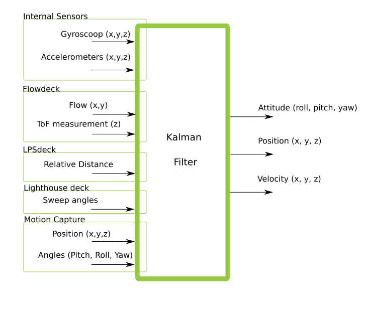
The (extended) Kalman filter is an step up in complexity compared to the complementary filter, as it accepts more sensor inputs of both internal and external sensors. It is an recursive filter that estimates the current state of the Crazyflie based on incoming measurements (in combination with a predicted standard deviation of the noise), the measurement model and the model of the system itself. We will not go into detail on this but we encourage people to learn more about (extended) Kalman filters by reading up some material like this.
Schematic overview of inputs and outputs of the Extended Kalman Filter
Shortly said, because of the more state estimation possibilities, we preferred the Kalman filter in combination with several decks: Flowdeck, Loco positioning deck and the lighthouse deck. If you look in the deck driver firmware (like for instance this one), you see that we set the required estimator to be the Kalman and that is of course because we want position/velocity estimates :). Important though is that each input of the measurement effects the quality of the position, as positioning of the Lighthouse deck (mm precision) is much more accurate that the loco positioning deck (cm precision), which has all to do with the standard deviation of the measurement of those values. Please check out the content of estimator_kalman.c and kalman_core.c to know more about the implementation. Also good to know that the Kalman filter has an supervisor, which resets if the position or velocity estimate is gets out of hand.
Of course this blogpost does not show the full detailed explanation of state estimation, but we do hope that it gives some kind of overview so you know where to look if you would like to improve anything. The Kalman filter can easily be extended to accept more inputs, or the models on which the estimates are based can be improved. If you would like implement your own filter, that would be perfectly possible to do so too.
It would be great if you guys could share your thoughts and questions about the state estimation on the crazyflie on the forum!