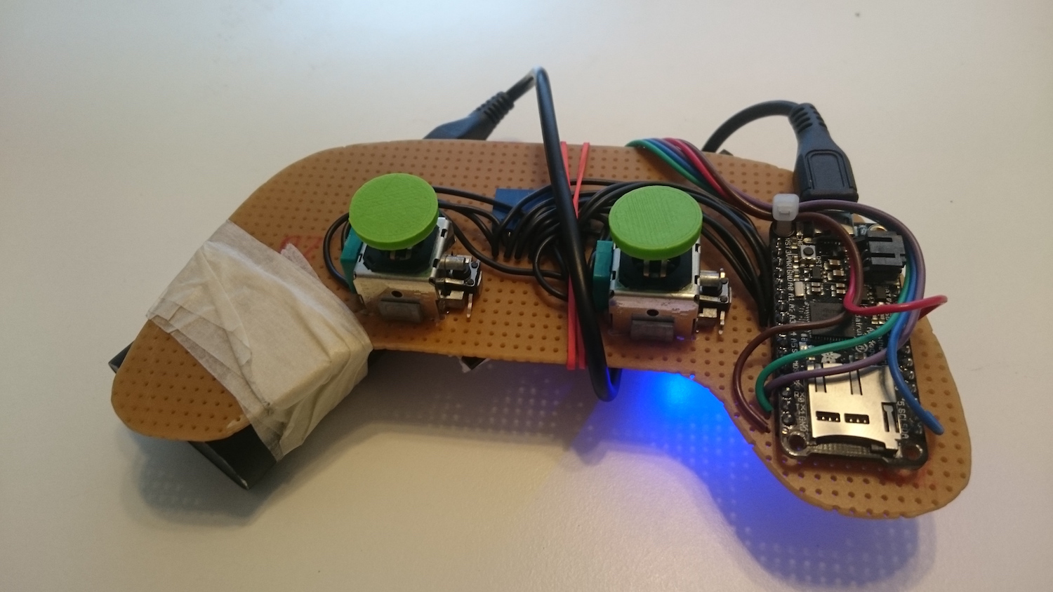
ST Microelectronics have become quite known for their complex and somewhat buggy I2C peripheral, especially for their STM32F103 device (see errata). Where for instance the I2C interrupt priority needs to be the highest in the system, otherwise some I2C events might be lost which could cause random behavior. Since we use the STM32F103 for the Crazyflie 1.0 we have been using ST provided drivers as a solution for not having to take care of these cases. On the Crazyflie 2.0 we’re using the STM32F405 which doesn’t have the same I2C implementation and where ST has moved over to using the CPAL library for I2C drivers. This driver has turned out to be “bulky” and cause compatibility problems with our FreeRTOS due to handling of CPAL timeouts. Therefore we recently decided to see if we could write our own driver for the STM32F405 instead. How hard can it be..? Well after two weeks of pulling my hair and swearing it turned out to be a bit harder than we first thought. But now we hopefully have a slick and optimized I2C driver that works great for our purpose. Instead of polling it uses interrupts for I2C writing and DMA for I2C reading to keep MCU intervention low, leaving more processing power to Kalman filters etc :-).
Like I said, there was a few more obstacles along the way than we initially thought. So here are are some pointers I collected on the way:
- I quickly dropped the interrupt event handling the ST-LIB suggest, I2C_GetLastEvent(…), because during the address event status register 2 (SR2) needs to be cleared (by reading it) after DMA has been setup (as noted in the datasheet when reading the fine print…). The I2C_GetLastEvent reads SR1 and SR2 at once which thus doesn’t work out.
- This took most time to find, but using my I2C analyser I found that the I2C connection suddenly stopped after a small period of time with a START then STOP event of 3.9us. Doing a lot of trial and error a eventually found that the only way to trigger such a quick start-stop condition was if both the start and stop flag in the control register where set at once. I therefore tried manipulating the CR1 register only with a write operation and not a read-modify-write which solved the problem. This requires that you know what the whole content of the register needs to be when setting it. Luckily such is the case. A very strange behaviour but now it’s working, let’s leve it at that :-)
- And finally don’t always trust the tools. I found that using my TotalPhase Beagle I2C analyzer I sometimes got corrupt transactions. I tried a lot of things in my I2C driver but I didn’t get why. I posted a topic in the ST forum to get some desperately needed help but then one of my colleges suggested that I should try a different analyser. Well there was no problems with the I2C bus according to that analyser. Turned out that the problem was that I was using the Totalphase Data Center software in a virtual machine. I couldn’t get it to run natively on Ubuntu, which must have been causing slow USB communication or something that the Data Center software doesn’t handle correctly.
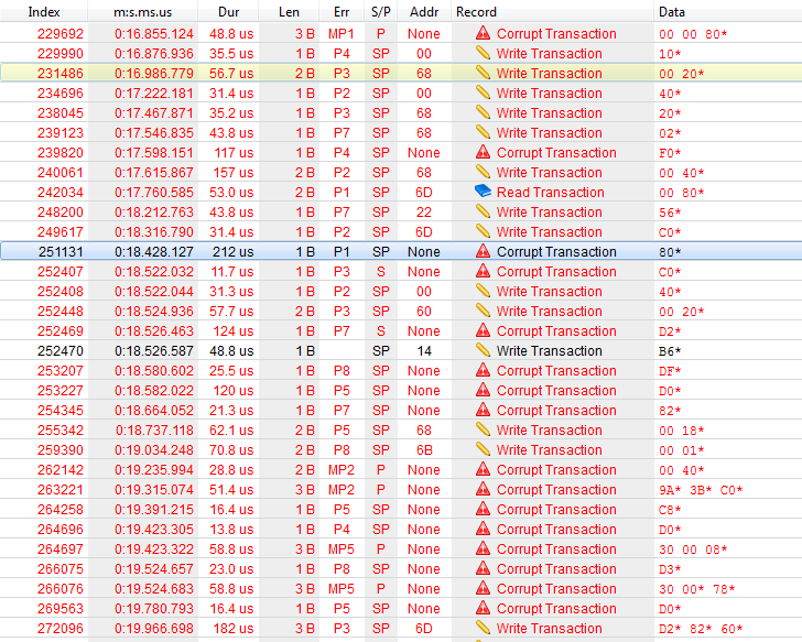
Random corrupt I2C transaction when used in VM