Our usual blog posts usually consists of the awesome new products and demos that we make here at Bitcraze, but now we will talk about… documentation! Alright alright, it is maybe not the most thrilling topic, however you should be excited about it! Good documentation about the Crazyflie and its tools will not only enable you to recreate the demos and the work of others, but also to implement your own ideas and to contribute to our open-source firmware.
In the years that Bitcraze has been around, there has been quite the build-up of information, which can be either found on the main website, the wiki, the github repositories, and in bits & pieces on the forum. Although we try to provide all the information necessary for getting started with development, it is currently quite a clutter. If we at Bitcraze already have difficulty of finding and maintaining all the documentation, we can only imagine how difficult it would be for a starting developer. We therefore would like to improve the flow of information dramatically!
Here are some ideas of what we would like to do with the documentation:
Moving product information to the shop.
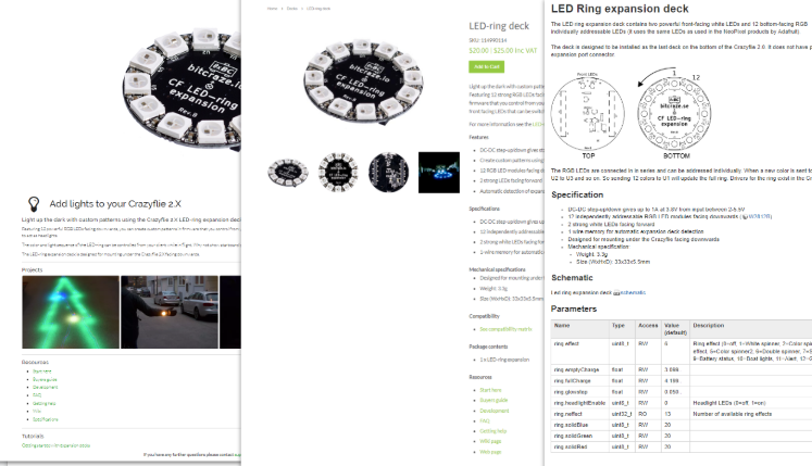
Currently there are three different locations where you can find information about physical Crazyflie, localization systems or expansion decks, which is the main website, the online store and the wiki. We see that a lot of electronic and hardware shops usually put all the details of the product directly on the product page of their shops. We aim to do that as well, since there will only be one page for users to go to for schematics, specifications, instructions and more, and for us it will be also easier to maintain and update any product information
Moving Software Info to GitHub
There is a lot of bits and pieces of information to handle the firmware on the Crazyflie and all the tools in the tutorials on our main website, wiki and Github repository. This again makes a lot of duplicate information, which is difficult for us to maintain and therefore gets easily outdated. We could put all the information on the wiki, but what if somebody changes something in the code which requires a change in the procedure as well?
It would be the best to keep all the information about the firmware as close to the source as possible, therefore we think is best to move everything to the github repositories. For instance, the wiki cfclient instructions can be moved to the documentation of the cfclient repostitory, or Onchip debugging instructions can go to crazyflie firmware repostitory To keep it all manageable we will:
- Create a /doc folder on the repositories to better structure all the information
- Add more Doxygen comments to all the function in the the codes and automatically generate documentation for this.
Restructuring the Wiki Content
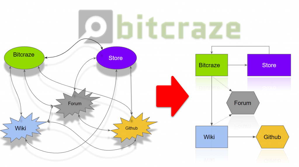
After moving all the hardware- related content to the shop, and moving all the firmwar- related info to the Github repositories, we will need to think about what we want to do with the Wiki! You would think that there is nothing left to put on the wiki anymore after the replacement of the earlier documentation, but we beg to differ! For instance, there is so many Github repositories that there is a really a need for an overview. The wiki can educate developers on which tools we have an how to properly use them. Of course, we already have the getting started tutorials, but we want to also provide a more in-depth explanation of the overall structure and how the different repositories would need tho work together, like this .
This does mean that we would need to restructure the wiki entirely and only focusing on topics like:
- System Architecture Crazyflie
- Communication protocol between STM and the NRF
- Communication protocol between the Python library and the Client
- Overview Github-repositories
- Projects and hacks
- etc etc
What do you think?!
Of course we can change all we want in the documentation, but you guys are the ones who actually use it! We are very curious of what what you think of the plans and give us more tips or suggestions on how to improve the overall documentation experience. Please leave a message below or express your opinion on this forum thread.