Storage is one of these very simple functionality that actually ends up being quite hard to implement properly. It is also one of these functionality that is never acutely needed, it is possible to hack around it, so it gets pushed to be implemented later. Later is now, we have now implemented a generic persistent storage subsystem in the Crazyflie.
In Crazyflie 1.0, we originally stored settings in a setting block in flash and required the bootloader to change the settings. When designing Crazyflie 2.0 we added an I2C EEPROM to make it easier to store settings, though until now we only stored a fix config block very similar to the one stored in the Crazyflie 1 and that only contained basic radio settings and tuning. This implementation is hard to evolve since the data structure is fixed in one point of the code.
What is now implemented is a generic key-buffer database stored in the I2C EEPROM. From the API user point of view, it is now possible to store, retrieve and delete a buffer using a string as a key. This allows any subsystem, or apps, in the Crazyflie to easily store and retrieve their own config blocks. There is 7KB of space available for storage in the EEPROM.
The first user of this new storage subsystem is the Lighthouse driver. The storage is used to store lighthouse basestation geometries and calibration data, this allows to configure a Crazyflie for a system/lab and have it running out of the box even after a restart.
A future use-case would be to implement stored-parameters: we have been thinking about implementing optional persistence for the parameters for a long time. This would allow to modify and then store new default values for any parameters already present in the Crazyflie. This would allow to very easily implement things like custom controller tuning in a quad made from a bolt for example.
At low level, we where hopping to be able to find a ready-to-use library or file system to store data in our small EEPROM, but unfortunately we did not find anything that would fit our needs. We then had to implement our own storage format.
The low level structure is documented in the Crazyflie firmware repos. Basically the data are stored as a table of “length-key-value” entries with a possibility for an entry to he a “hole”. When new buffers are added they are added at the end of the table and when they are deleted they are replaced by a hole. When the end of the table is reached, the table is de-fragmented by removing the holes and moving the data as much as possible to the beginning of the memory. This structure works very well for an EEPROM and could even be adapted to work well on FLASH.
New CI
When we started activating continuous integration/automatic build to our GitHub repos we did so using Travis CI for firmware builds and AppVeyor for windows builds. However, the GitHub CI offering, GitHub actions, has become quite complete lately and now supports Linux, Windows as well as MacOS builds.
We have now transitioned to GitHub actions for all our repos and we will also implement most of the release process using GitHub actions as well. This will hopefully streamline the release process and allow us to release new version of our projects more often.
With the raging pandemic in the world, 2021 will most likely not be an ordinary year. Not that any year in the Bitcraze universe has been boring and without excitement so far, but it is unusually hard to make predictions about 2021. Any how, we will try to outline what we see in the crystal ball for the coming year.
Products
What products are cooking in the Bitcraze pot and what tasty new gadgets can we look forward to this year?
Lighthouse
We did hope that we would be able to release the first official version of the Lighthouse system in 2020, but unfortunately we did not make it. It has turned out to be more complex than anticipated but we do think we are fairly close now and that it will be finished soonish, including support for lighthouse V2.
Once the official version has been achieved, we are planning to assemble an full lighthouse bundle, which includes everything you need to start flying in the lighthouse positioning system. This will also include the Basestations V2 as developed by Valve corporation, so stay tuned!
New platforms and improvements
We released the AI-deck last year in early release, but the AIdeck will be soon upgraded with the latest version of the GAP8 chip. For most users this will not change much but for those that really push the deep learning to the edge will be quite happy with this improvement. More over, we are planning to by standard equipped the gray-scale camera instead of the RGB Bayer filter version, due to feedback of the community. We are still planning to offer the color camera on the side as a separate product for those that do value the color information for their application.
Also we noticed the released of several upgraded versions of sensors for the decks that we already are offering today. Pixart and ST have released a new TOF and motion sensor so we will start experimenting with those soon which hopefully lead to a new Multiranger or Flowdeck. Also we are aware of the new DWM3000 chip which would be a nice upgrade to the LPS system, so we will start exploring that as well, however we are not sure if we will be able to release the new version of LPS in 2021 already.
One of the field that we have wanted to improve for a while but have not gotten to so far is the communication with the Crazyflie. The Crazyradio is using a quite old chip and the communication protocol has hardly been touched in years. There now exists a much more powerful nRF52 radio chip with USB port so it can give us the opportunity to make a new Crazyradio and, at the same time, rework the communication protocols to make them more reliable, easier to use and to expand.
People and Collaborations
Last year we have started several collaborations with show drone orientated business, which we are definitely moving forward with in 2021. For shows stability and performance is very important so with the feedback of those that work with that on a regular basis will be crucial for the further development and reliability of our products.
Moreover we would like to continue our close collaboration with researchers at institutes and universities, to help them out with achieving their goals and contribute their work to our opensource firmware and software. Here we want to encourage the community to make their contributions easy to use by others, therefore increasing the reproducibility of the implementations, which is a crucial aspect of research. Also we are planning to have more of our online tutorial like the one we had in November.
We also will be working with closely together with one of our very active community members, Wolfgang Hönig! He has done a lot of great work for the Crazyswarm project from his time at University of Southern California (USC) and has spend the last few years at Caltech. He will be working together with us for a couple of months in the spring so we will be very happy to have him. Moreover, we will also have 2 master students from LTH working with us on the topic hardware simulation in the spring. We are making sure that we can all work together in the current situation, either sparsely at the office or fully online.
In 2021, we will also keep our eyes open for new potential Bitcrazers! We believe that everybody can add her/his own unique addition to the team and therefore it is important for us to keep growing and get new/fresh ideas or approaches to our problem. Usually we would meet new people at conferences but we will try new virtual ways to get to know our community and hopefully will meet somebody that can enhance our crazy group.
Working from home
Due to the pandemic we are currently mainly working from home and from the looks of it, this will continue a while. Even though we think we have managed to find a way to work remotely that is fairly efficient, it is still not at the same level as meeting in real-life, so there is always room for improvement. Further more the lack of access to electronics lab, flight lab and other facilities when working from home, does not speed work up. We will try to do our best though under the current circumstances and are looking forward to an awesome 2021!
2020 was not an ordinary year, and through its different roller coaster motions, we’re proud of what we’ve accomplished. As 2021 grows nearer, it’s time to look back at this year and appreciate our accomplishments.
Community
The Crazyflie is still gaining a lot of interests in universities, and we’re always happy to discover what awesome things our users are doing with our products. One of our proudest moment was that a paper published in Science magazine used a Crazyflie in their research framework!
We actually made a montage of the different research videos where the Crazyflie, and we feel blessed to be part of those amazing feats. We were also quite surprised to see how the Crazyflie is implemented in different fields. Here is the video if you want to know more:
We’ve had stellar blogposts from guests this year, that you can read if you missed:
Of course, “community” this year means something different. We were sorry to not participate in the conventions and fairs where we usually meet a lot of interesting people, and had to find ways to do things differently. We now have a Discord server where people can join and discuss all things Bitcraze related!
Hardware
In the beginning of the year, we started right by releasing the Active Marker deck. Thanks to our collaboration with Qualisys, this new motion capture sensor can estimate the full body pose of the Crazyflie without unique marker positions or known starting positions.
A great deal of work was dedicated to the release of the AI deck in early access. Thanks to our newest deck, super-edge-computing is now possible on your Crazyflie !
Software
We improved our app API. We have seen it used more and more. Being able to add code to the Crazyflie without having to fork the code has proven to be quite useful and popular.
At the beginning of the year we finally managed to decode and use the Lighthouse V2 signals in order to get the Crazyflie to fly autonomously using lighthouse V2 basestations. Our focus for the end of year was to improve the Lighthouse V2, and thanks to some hard work, we managed to improve the calibration compensation for the newest version of Valve’s base station.
The client got a new facelift, as well as the python lib, and we released no less than 4 different new releases.
Documentation
We tried as much as we can to improve our documentation, and working from home proved how much it is needed. Kimberly wrote some step-by-step guides that help you discover more hands-on how to use our python library and the motion commander.
We also tried a new way to connect with you, while improving our existing tutorials, by having an online tutorial. It proved quite successful and it was a great way to talk about all the possibilities (and difficulties!) of a swarm.
The way we work
The biggest change was, as many of you, to learn to work from home. We managed quite well, learning to adapt our process. We now are experts in flying at home, and even though our flying arena is deserted, our kitchens are now more alive than ever.
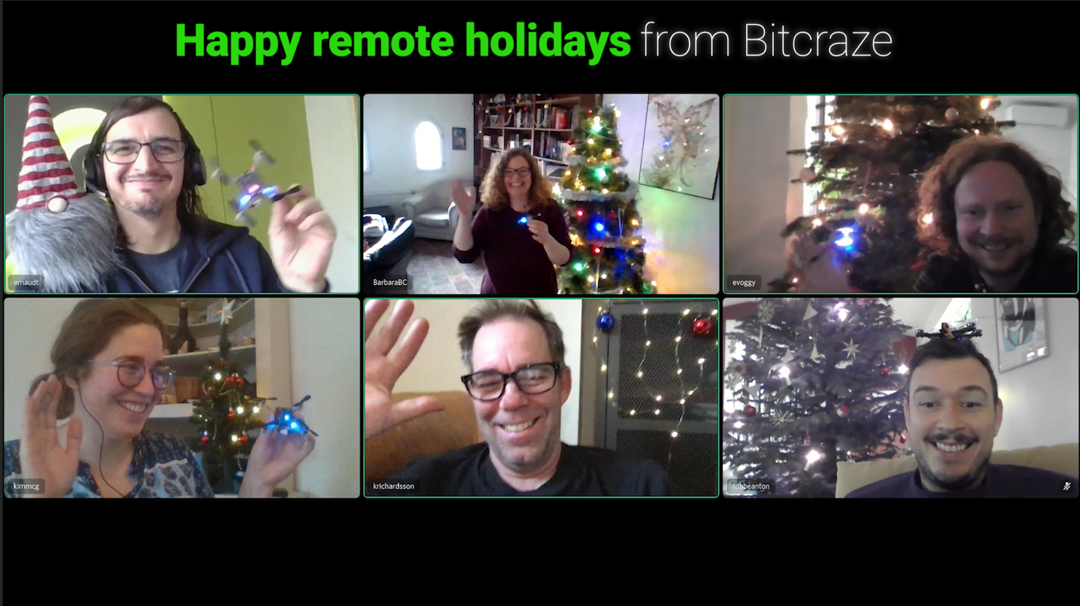
It’s that time of the year again ! As the days get darker and darker here in Sweden, we’re happy to getting some time off to share some warmth with our families.
And to kick off the holiday season, we prepared a little treat for you ! We enjoyed making a Christmas video that tested how we could use the Crazyflie at home. Since we’re not at the office anymore, we decided to fly in our homes and this video shows the different ways to do so. First, take a look at what we’ve done:
Now let’s dig into the different techniques we used.
Tobias decided to fly the Bolt manually. His first choice was to land in the Christmas sock, but that was too hard, thereof the hard landing in top of the tree. We were not sure who would survive: the tree or the Bolt!
Kimberly installed two base stations V2’s and after setting up, determined some way points by holding the Crazyflie in her hand. Then she generated a trajectory with the uav_trajectories project (like in the hyper demo). Then she used the cflib to upload this trajectory and make the crazyflie fly all the way to the basket. Her two cats could have looked more impressed, though!
Using trials and errors, Barbara used the Flowdeck, the motion commander, and a broken measuring tape to calibrate the Crazyflie’s path next to the tree.
Arnaud realized that, with all the autonomous work, we hardly fly the Crazyflie manually anymore. So he flew the Crazyflie manually. It required a bit more training that expected, but Crazyflie is really a fun (and safe!) quad to fly.
Marcus used two Lighthouse V2 base stations together with the Lighthouse deck and LED-ring deck. For the flying, he used the high level commander. The original plan was to fly around his gingerbread house, but unfortunately it was demolished before he got the chance (by some hungry elves surely!)
Kristoffer made his own tree ornament with the drone, which turned out to be a nice addition to a Christmas tree !
It was a fun way to use our own product, and to show off our decorated houses.
I hope you enjoy watching this video as much as we enjoyed making it.
We are staying open during the Holiday season but on a limited capacity: we still ship your orders, and will keep an eye on our emails and the forum, but things will get a bit slower here.
We wish you happy holidays and safe moments together with your loved ones.
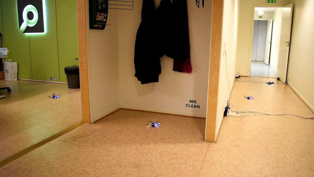
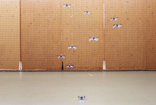
This autumn when we had our quarterly planing meeting, it was obvious that there would not be any conferences this year like other years. This meant we would not meet you, our users and hear about your interesting projects, but also that we would not be forced to create a demo. Sometimes we joke that we are working with Demo Driven Development and that is what is pushing us forward, even-though it is not completely true it is a strong driver. We decided to create a demo in our office and share it online instead, we hope you enjoy it!
The wish list for the demo was long but we decided that we wanted to use multiple positioning technologies, multiple platforms and multiple drones in a swarm. The idea was also to let the needs of the demo drive development of other technologies as well as stabilize existing functionality by “eating our own dogfood”. As a result of the work we have for instance:
improved the app layer in the Crazyflie
Lighthouse V2 support, including basic support for 2+ base stations
better support for mixed positioning systems
First of all, let’s check out the video
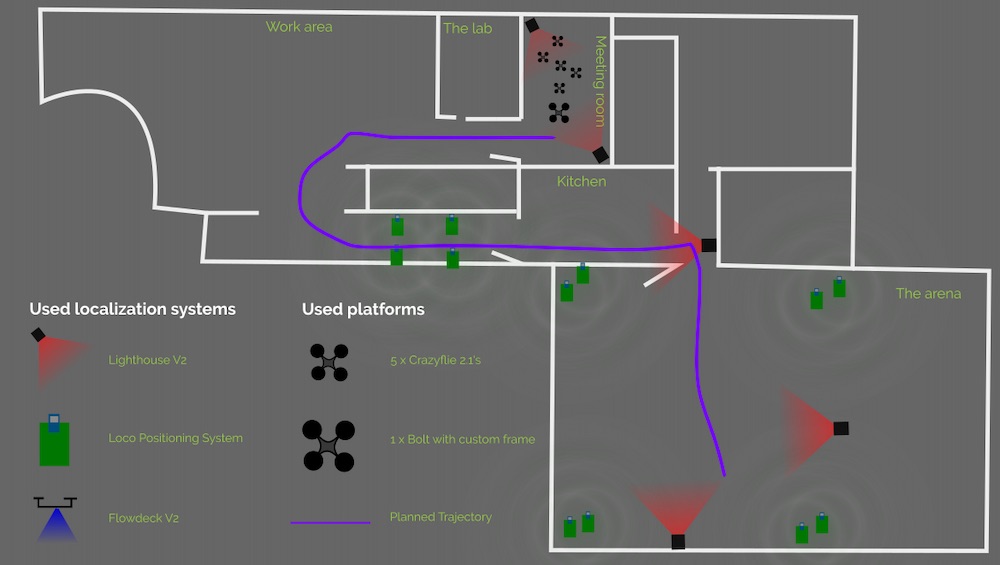
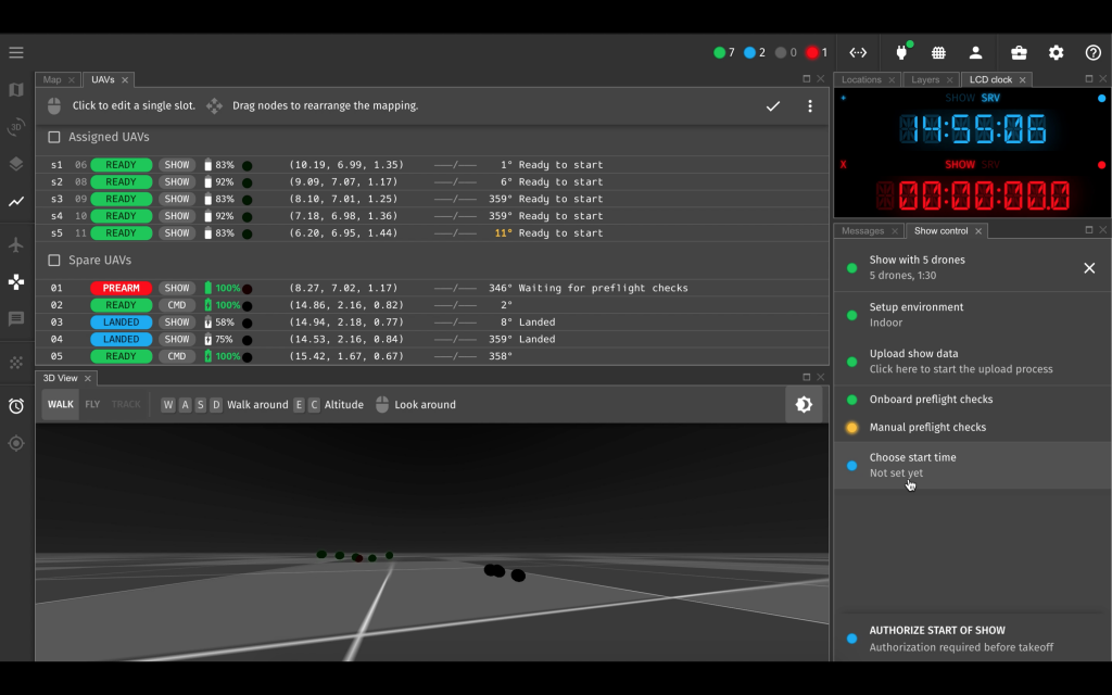
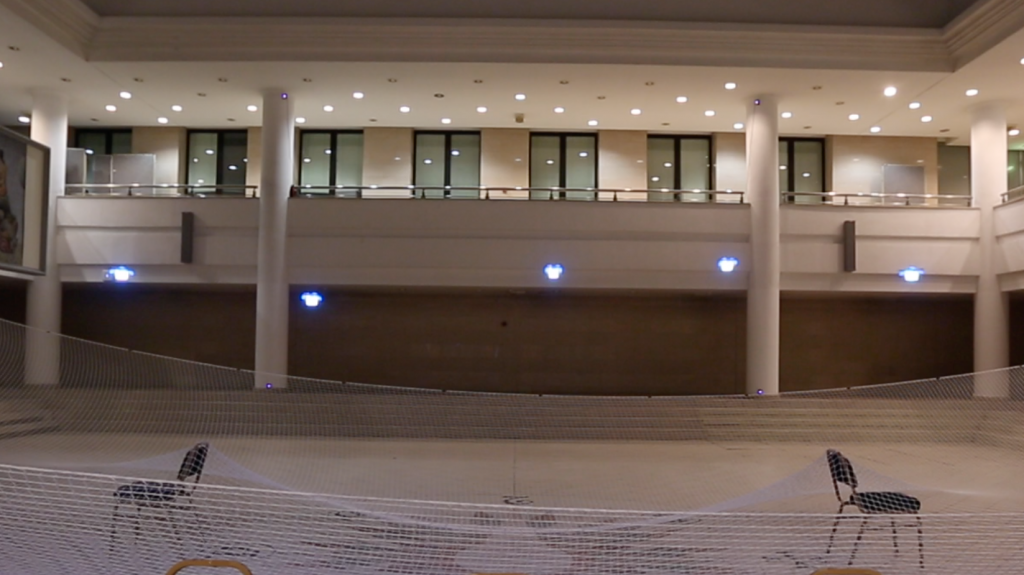
We are using our office for the demo and the Crazyflies are essentially flying a fixed trajectory from our meeting room, through the office and kitchen to finally land in the Arena. The Crazyflies are autonomous from the moment they take off and there is no communication with any external computer after that, all positioning is done on-board.
Implementation
The demo is mainly implemented in the Crazyflie as an app with a simple python script on an external machine to start it all. The app is identical in all the Crazyflies so the script tells them where to land and checks that all Crazyflies has found their position before they are started. Finally it tells them to take off one by one with a fixed delay in-between.
The Crazyflie app
When the Crazyflie boots up, the app is started and the first thing it does is to prepare by defining a trajectory in the High Level Commander as well as setting data for the Lighthouse base stations in the system. The app uses a couple of parameters for communication and at this point it is waiting for one of the parameters to be set by the python script.
When the parameter is set, the app uses the High Level Commander to take off and fly to the start point of the trajectory. At the starting point, it kicks off the trajectory and while the High Level Commander handles the flying, the app goes to sleep. When reaching the end of the trajectory, the app once more goes into action and directs the Crazyflie to land at a position set through parameters during the initialization phase.
We used a feature of the High Level Commander that is maybe not that well known but can be very useful to make the motion fluid. When the High Level Commander does a go_to for instance, it plans a trajectory from its current position/velocity/acceleration to the target position in one smooth motion. This can be used when transitioning from a go_to into a trajectory (or from go_to to go_to) by starting the trajectory a little bit too early and thus never stop at the end of the go_to, but “slide” directly into the trajectory. The same technique is used at the end of the trajectory to get out of the way faster to avoid being hit by the next Crazyflie in the swarm.
The trajectory
The main part of the flight is one trajectory handled by the High Level Commander. It is generated using the uav_trajectories project from whoenig. We defined a number of points we wanted the trajectory to pass through and the software generates a list of polynomials that can be used by the High Level Commander. The generated trajectory is passing through the points but as a part of the optimization process it also chooses some (unexpected) curves, but that could be fixed with some tweaking.
The trajectory is defined using absolute positions in a global coordinate system that spans the office.
Positioning
We used three different positioning systems for the demo: the Lighthouse (V2), the Loco Positioning system (TDoA3) and the Flow deck. Different areas of the flight space is covered by different system, either individually or overlapping. All decks are active all the time and pick up data when it is available, pushing it into the extended Kalman estimator.
In the meeting room, where we started, we used two Lighthouse V2 base stations which gave us a very precise position estimate (including yaw) and a good start. When the Crazyflies moved out into the office, they only relied on the Flowdeck and that worked fine even-though the errors potentially builds up over time.
When the Crazyflies turned around the corner into the hallway towards the kitchen, we saw that the errors some times were too large, either the position or yaw was off which caused the Crazyflies to hit a wall. To fix that, we added 4 LPS nodes in the hallway and this solved the problem. Note that all the 4 anchors are on the ground and that it is not enough to give the Crazyflie a good 3D position, but the distance sensor on the Flow deck provides Z-information and the overall result is good.
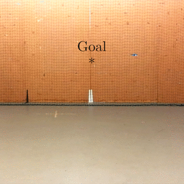
The corner when going from the kitchen into the Arena is pretty tight and again the build up of errors made it problematic to rely on the Flow deck only, so we added a lighthouse base station for extra help.
Finally, in the first part of the Arena, the LPS system has full 3D coverage and together with the Flow deck it is smooth sailing. About half way the Crazyflies started to pick up the Lighthouse system as well and we are now using data from all three systems at the same time.
Obviously we were using more than 2 basestations with the Lighthouse system and even though it is not officially supported, it worked with some care and manual labor. The geometry data was for instance manually tweaked to fit the global coordinate system.
The wall between the kitchen and the Arena is very thick and it is unlikely that UWB can go through it, but we still got LPS data from the Arena anchors occasionally. Our interpretation is that it must have been packets bouncing on the walls into the kitchen. The stray packets were picked up by the Crazyflies but since the Lighthouse base station provided a strong information source, the LPS packets did not cause any problems.
Firmware modifications
The firmware is essentially the stock crazyflie-firmware from Github, however we did make a few alterations though:
The maximum velocity of the PID controller was increased to make it possible to fly a bit faster and create a nicer demo.
The number of lighthouse base stations was increased
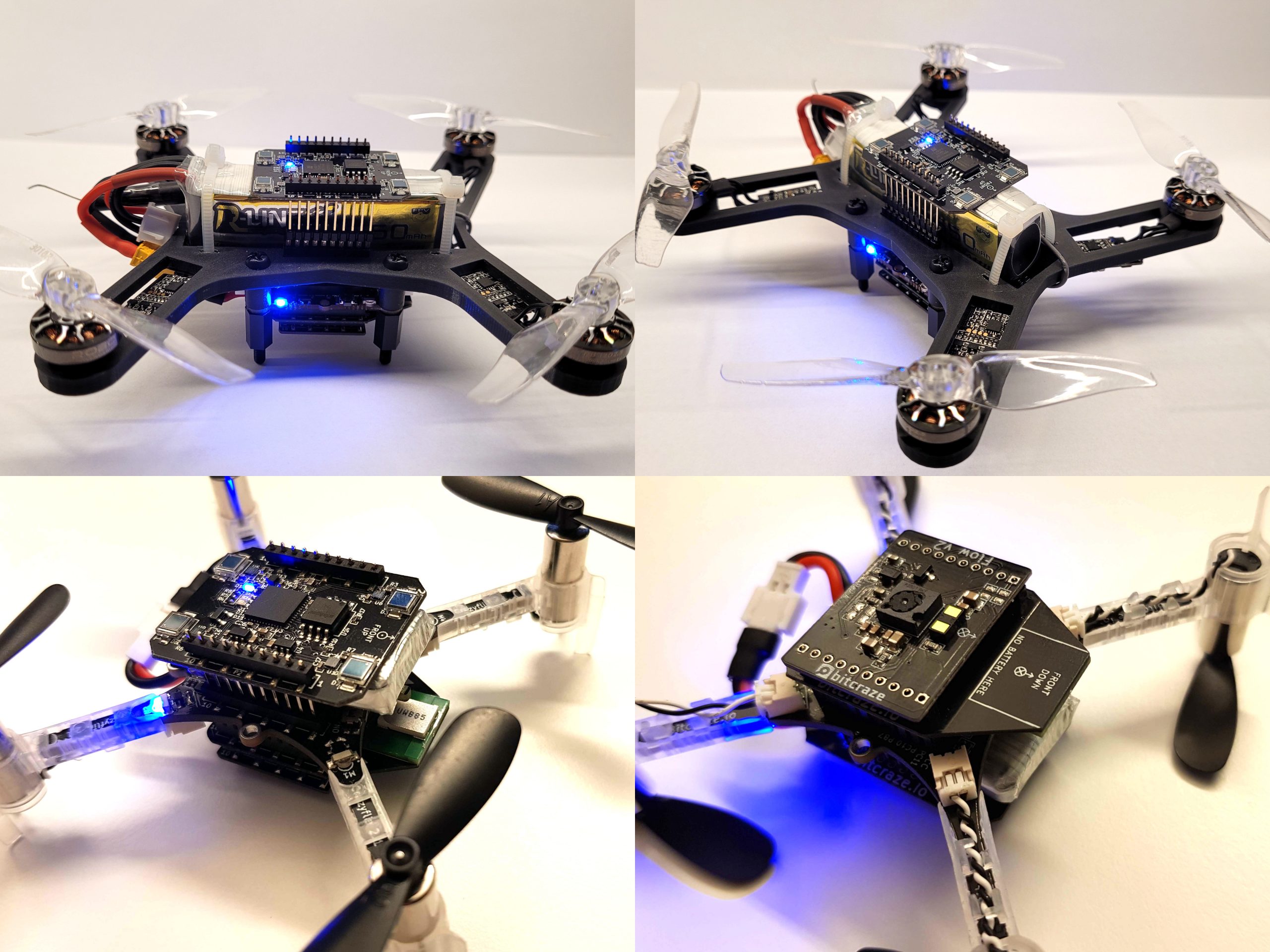
In the demo we used 5 x Crazyflie 2.1 and 1 x Bolt very similar to the Li-Ion Bolt we built recently. The difference is that this version used a 2-cell Li-Po and lower KV motors but the Li-Ion Bolt would have worked just as well.
Hyperdemo drones and they configurations
To make all positioning to work at the same time we needed to add 3 decks, Lighthouse, Flow v2 and Loco-deck. On the Crazyflie 2.1 this fits if the extra long pin-headers are used and the Lighthouse is mounted on top and the Loco-deck underneath the Crazyflie 2.1 with the Flow v2 on the bottom. The same goes for the Bolt, but here we had to solder the extra long pin-header and the long pin-header together to make them long enough.
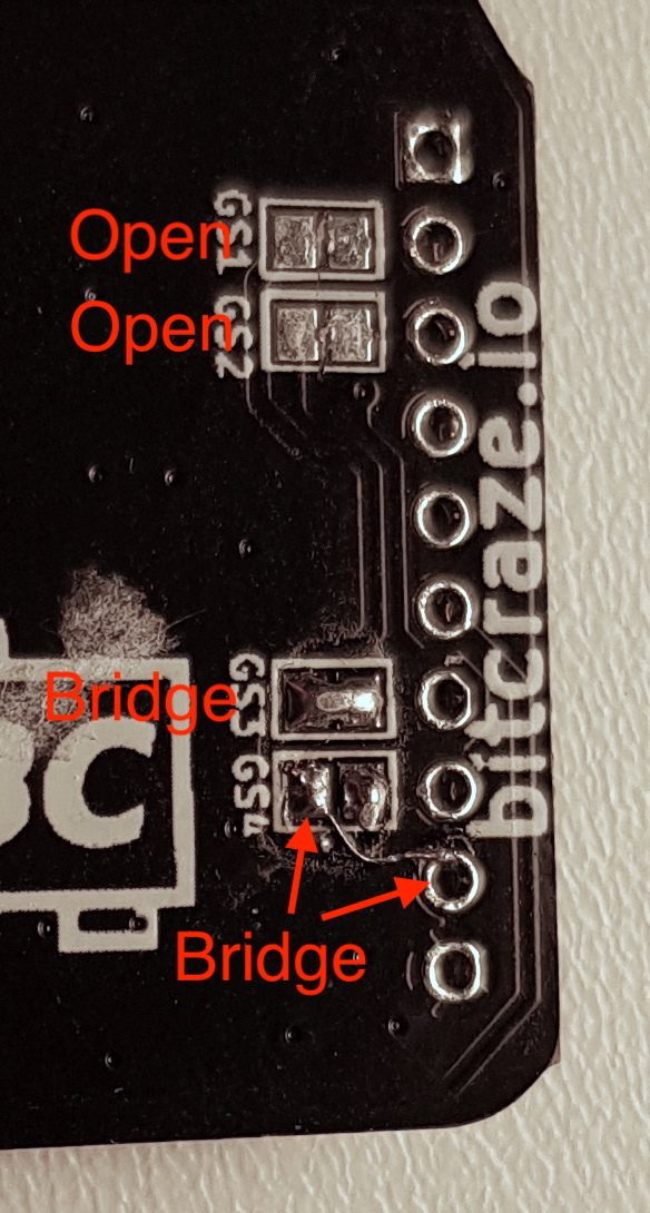
There is one catch though… the pin resources for the decks collide. With some patching of the loco-deck this can be mitigated by moving its IRQ to IO_2 using the solder-jumper. The RST needs to be moved to IO_4 which requires a small patch wire.
Also some FW configuration is needed which is added to the hyperdemo makefile:
The final weight for the Crazyflie 2.1 is on the heavy side and we quickly discover that fully charged batteries should be used or else the crash probability is increased a lot.
Conclusions
We’re happy we were able to set this demo up and that it was fairly straight forward. The whole setup of it was done in one or two days. The App layer is quite useful and we tend to use it quite often when trying out ideas, which we interpret as a good sign :-)
We are satisfied with the results and hope it will inspire some of you out there to push the limits even further!
The Holiday season is already in full gear here, with Christmas lights everywhere, and even though it’s not going to be an usual celebration for many of us, we’re trying to find ways to make it memorable.
Our first thought for preparing the year to come (other than hoping for less dire circumstances worldwide) is to find out how we can better your experience.
Since this summer, we’ve been wondering how to improve ourselves. We have made some great headways in stabilizing what we offer. Whether with our documentation (new step-by-step guides and online tutorials), our hardware (our new propellers work perfectly) or our software (a new client and app API), we tried to improve what we already have.
We pride ourselves in knowing our defaults, but we strive to correct them as much as we can. However, we’re aware that we’re not perfect, and have some blind spots. Be that as it may, improving ourselves means also knowing where there’s room for improvement! And that’s where you are needed.
We’d like to know your thoughts and feedback, and the best way to learn from you is to ask you questions. So we created a quick survey: it takes only 3 minutes to answer and would help us a lot. In fact, it will help us shape 2021, or at least the beginning of it, as we want to stabilize our portfolio and our documentation. The goal of the survey is to pinpoint the areas that need improvements and to gain general knowledge on our customers.
Click here if you want to help and answer the survey!
A Christmas party !
And, before we start 2021 with your feedback, we’d like to hear from you in real time! We’re indeed planning a Bitcraze Christmas gathering, on:
Day: Tuesday December 15th
Time: 17:00 Central European Time (Malmö, Sweden).
It would be nice to join us with some (virtual) mulled wine, to talk about the Crazyflie, or share some Christmas spirit together . We promise we won’t sing any Christmas carols, but maybe we can show some nice videos!
So join us on the Discord server where we will provide further information and open up a video&voice channel/Mozilla hubs room on the day itself.
This week we have a guest blog post from CollMot about their work to integrate the Crazyflie with Skybrush. We are happy that they have used the app API that we wrote about a couple of weeks ago, to implement the required firmware extensions!
Bitcraze and CollMot have joined forcesto release an indoor drone show management solution using CollMot’s new Skybrush softwareand Crazyflie firmware and hardware.
CollMot is a drone show provider company from Hungary, founded by a team of researchers with a decade-long expertise in drone swarm science. CollMot offers outdoor drone shows since 2015. Our new product, Skybrush allows users to handle their own fleet-level drone missions and specifically drone shows as smoothly as possible. In joint development with the Bitcraze team we are very excited to extend Skybrush to support indoor drone shows and other fleet missions using the Crazyflie system.
The basic swarm-induced mindset with which we are targeting the integration process is scalability. This includes scalability of communication, error handling, reliability and logistics. Each of these aspects are detailed below through some examples of the challenges we needed to solve together. We hope that besides having an application-specific extension of Crazyflie for entertainment purposes, the base system has also gained many new features during this great cooperative process. But lets dig into the tech details a bit more…
UWB in large spaces with many drones
We have set up a relatively large area (10x20x6 m) with the Loco Positioning System using 8 anchors in a more or less cubic arrangement. Using TWR mode for swarms was out of question as it needs each tag (drone) to communicate with the anchors individually, which is not scalable with fleet size. Initial tests with the UWB system in TDoA2 mode were not very satisfying in terms of accuracy and reliability but as we went deeper into the details we could find out the two main reasons of inaccuracies:
Two of the anchors have been positioned on the vertical flat faces of some stairs with solid material connection between them that caused many reflections so the relative distance measurements between these two anchors was bi-stable. When we realized that, we raised them a bit and attached them to columns that had an air gap in between, which solved the reflection issue.
The outlier filter of the TDoA2 mode was not optimal, a single bad packet generated consecutive outliers that opened up the filter too fast. This issue have been solved since then in the Crazyflie firmware after our long-lasting painful investigation with changing a single number from 2 to 3. This is how a reward system works in software development :)
After all, UWB was doing its job quite nicely in both TDoA2 and TDoA3 modes with an accuracy in the 10-20 cm level stably in such a large area, so we could move on to tune the controller of the Crazyflie 2.1 a bit.
Crazyflies with Loco and LED decks
As we prepared the Crazyflie drones for shows, we had the Loco deck attached on top and the LED deck attached to the bottom of the drones, with an extra light bulb to spread light smoothly. This setup resulted in a total weight of 37g. The basic challenge with the controller was that this weight turned out to be too much for the Crazyflie 2.1 system. Hover was at around 60-70% throttle in average, furthermore, there was a substantial difference in the throttle levels needed for individual motors (some in the 70-80% range). The tiny drones did a great job in horizontal motion but as soon as they needed to go up or down with vertical speed above around 0.5 m/s, one of their ESCs saturated and thus the system became unstable and crashed. Interestingly enough, the crash always started with a wobble exactly along the X axis, leading us to think that there was an issue with the positioning system instead of the ESCs. There are two possible solutions for this major problem:
use less payload, i.e. lighter drones
use stronger motors
Partially as a consequence of these experiments the Bitcraze team is now experimenting with new stronger models that will be optimized for show use cases as well. We can’t wait to test them!
Optimal controller for high speeds and accurate trajectory following
In general we are not yet very satisfied with any of the implemented controllers using the UWB system for a show use-case. This use-case is special as trajectory following needs to be as accurate as possible both in space and time to avoid collisions and to result in nice synchronized formations, while maximal speed both horizontally and vertically have to be as high as possible to increase the wow-effect of the audience.
The PID controller has no cutoffs in its outputs and with the sometimes present large positioning errors in the UWB system controller outputs get way too large. If gains are reduced, motion will be sluggish and path is not followed accurately in time.
The Mellinger and INDI controllers work well only with positioning systems of much better accuracy.
We stuck with the PID controller so far and added velocity feed forward terms, cutoffs in the output and some nonlinearity in case of large errors and it helped a bit, but the solution is not fully satisfying. Hopefully, these modifications might be included in the main firmware soon. However, having a perfect controller with UWB is still an open question, any suggestions are welcome!
Show specific improvements in the firmware
We implemented code that uploads the show content to the drones smoothly, performs automatic preflight checking and displays status with the LED deck to have visual feedback on many drones simultaneously, starts the show on time in synchrony with all swarm members and handles the light program and show trajectory execution of the show.
These modifications are now in our own fork of the Crazyflie firmware and will be rewritten soon into a show app thanks to this new promising possibility in the code framework. As soon as Skybrush and Crazyflie systems will be stable enough to be released together, we will publish the related app code that helps automating show logistics for every user.
Summary
To sum it up, we are very enthusiastic about the Crazyflie system and the great team behind the scenes with very friendly, open and cooperative support. The current stage of Crazyflie + Skybrush integration is as follows:
New hardware iterations based on the Bolt system that support longer and more dynamic flights are coming;
a very stable, UWB-compatible controller is still an open question but current possibilities are satisfying for initial tests with light flight dynamics;
a new Crazyflie app for the drone show case is basically ready to be launched together with the release of Skybrush in the near future.
If you are interested in Skybrush or have any questions related to this integration process, drop us an email or comment below.
As many European countries, Sweden is now suffering the effects of the second COVID-19 wave. In line with current local restrictions we’re limiting the number of people at our office, which for us means no external guests and only a few people at a time. Although for customers there won’t be any difference since we’re still keeping our regular shipping (1-2 days after placing the order).
Stock levels
During the next couple of weeks we’re going to be short on some of our products, specifically the Swarm bundle, Loco Positioning deck and AI deck. We’re working hard to get them back into stock, and they are scheduled to arrive first weeks of December.
Lighthouse progress
Lately we have been working on finalizing the support for two lighthouse base stations (V1 as well as V2) in the firmware and python lib, which means that we are messing around with large portions of the lighthouse code. As some of you may have noticed it also means that the code base is unstable from time to time. It is likely that it will take a couple of more weeks before it settles down and it might be a good idea to avoid the latest commit if you are looking for a fully working and documented system. Hopefully we will have a good base for future releases and functionality when we are done.
The latest official stable release is 2020.09 and this is also what we recommend for now.
This week we have a guest blog post from Bárbara Barros Carlos, PhD candidate at DIAG Robotics Lab. Enjoy!
Quadrotors are characterized by their underactuation, nonlinearities, bounded inputs, and, in some cases, communication time-delays. The development of their maneuvering capability poses some challenges that cover dynamics modeling, state estimation, trajectory generation, and control. The latter, in particular, must be able to exploit the system’s nonlinear dynamics to generate complex motions. However, the presence of communication time-delay is known to highly degrade control performance.
A composite image showing our real-time NMPC with time-delay compensation being used on the Crazyflie during the tracking of a helical trajectory.
In our recent work, we present an efficient position control architecture based on real-time nonlinear model predictive control (NMPC) with time-delay compensation for quadrotors. Given the current measurement, the state is predicted over the delay time interval using an integrator and then passed to the NMPC, which takes into account the input bounds. We demonstrate the capabilities of our architecture using the Crazyflie 2.1 nano-quadrotor.
Time-Delay Compensation
In our aerial system, because of the radio communication latency, we have delays both in receiving measurements and sending control inputs. Likewise, since we intend to use NMPC, the potentially high computational burden associated with its solution becomes an element that must also be taken into account to minimize the error in the state prediction.
Crazyflie NMPC response without considering the time-delay compensation.
To tackle this issue, we use a state predictor based on the round-trip time (RTT) associated with the sum of network latencies as a delay compensator. The prediction is computed by performing forward iterations of the system dynamic model, starting from the current measured state and over the RTT, through an explicit Runge Kutta 4th order (ERK4) integrator. Due to the independent nature of this operation, perfect delay compensation can be achieved by adjusting the integration step to be equal to the RTT. Thus, it is assumed that there is a fixed RTT, defined by τr, to be compensated.
Nonlinear Model Predictive Control
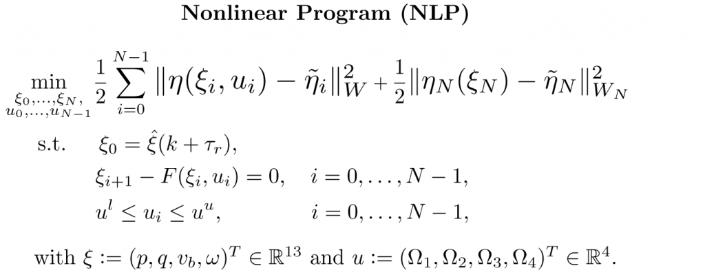
The NMPC controller is defined as the following constrained nonlinear program (NLP):
Therein, p denotes the inertial position, q the attitude in unit quaternions, vb the linear velocity expressed in the body frame, ω the angular rate, and Ωi the rotational speed of the ith propeller. The NLP is tailored to the Crazyflie 2.1 and is implemented using the high-performance software package acados, which solves optimal control problems and implements a real-time iteration (RTI) variant of a sequential quadratic programming (SQP) scheme with Gauss-Newton Hessian approximation. The quadratic subproblems (QP) arising in the SQP scheme are solved with HPIPM, an interior-point method solver, built on top of the linear algebra library BLASFEO, finely tuned for multiple CPU architectures. We use a recently proposed Hessian condensing algorithm particularly suitable for partial condensing to further speed-up solution times.
When designing an NMPC, choosing the horizon length has profound implications for computational burden and tracking performance. For the former, the longer the horizon, the higher the computational burden. As for the latter, in principle, a long prediction horizon tends to improve the overall performance of the controller. In order to select this parameter and achieve a trade-off between performance and computational burden, we implemented the NLP in acados considering: five horizon lengths (N = {10,20,30,40,50}), input bounds on the rotational speed of the propellers (lower bound = 0, upper bound = 22 krpm), discretizing the dynamics using an ERK4 integration scheme. Likewise, we compare the condensing approach with the state-of-the-art solver qpOASES against the partial condensing approach with HPIPM, concerning the set of horizons regarded.
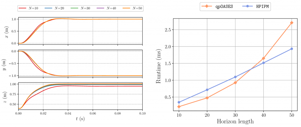
Left: closed-loop trajectories comparing different horizon lengths. Right: average runtimes per SQP-iteration for different horizon lengths considering two distinct QP solvers.
As qpOASES is a solver based on active-set method, it requires condensing to be computationally efficient. In line with the observations found in the literature that condensing is effective for short to medium horizon lengths, we note that qpOASES is competitive for horizons up to approximately N = 30 when compared to HPIPM. The break-even point moves higher on the scale for longer horizons, mainly due to efficient software implementations that cover: (a) Hessian condensing procedure tailored for partial condensing, (b) structure-exploiting QP solver based on novel Riccati recursion, (c) hardware-tailored linear algebra library. Therefore, we chose horizon N = 50 as it offers a reasonable trade-off between deviation from the reference trajectory and computational burden.
Onboard Controller Considerations
How the onboard controllers (PIDs) use the setpoints of the offboard controller (NMPC) in our architecture is not entirely conventional and, thereby, deserves some considerations. First, the reference signals that the PID loops track do not fully correspond to the control inputs considered in the NMPC formulation. Instead, part of the state solution is used in conjunction with the control inputs to reconstruct the actual input commands passed as a setpoint to the Crazyflie. Second, a part of the reconstructed input commands is sent as a setpoint to the outer loop (attitude controller), and the other part is sent to the inner loop (rate controller). Furthermore, as the NMPC model does not include the PID loops, it does not truly represent the real system, even in the case of perfect knowledge of the physical parameters. As a consequence, the optimal feedback policy is distorted in the real system by the PIDs.
Closed-loop Position Control Performance
Our control architecture hinges upon a ROS Kinetic framework and runs at 66.67 Hz. The Crazy RealTime Protocol (CRTP) is used in combination with our crazyflie_nmpc stack to stream in runtime custom packages containing the required data to reconstruct the part of the measurement vector that depends on the IMU data. Likewise, the cortex_ros bridge streams the 3D global position of the Crazyflie, which is then passed through a second-order, discrete-time Butterworth filter to estimate the linear velocities.
To validate the effectiveness of our control architecture, we ran two experiments. For each experiment, we generate a reference trajectory on a base computer and pass it to our NMPC ROS node every τs = 15 ms. When generating the trajectories, we explicitly address the feasibility issue in the design process, creating two references: one feasible and one infeasible. In addressing this issue, we prove through experiments that the performance of the proposed NMPC is not degraded even when the nano-quadrotor attempts to track an infeasible trajectory, which could, in principle, make it deviate significantly or even crash.
Overall, we observe that the most challenging setpoints to be tracked are the positions in which, given a change in the motion, the Crazyflie has to pitch/roll in the opposite direction quickly. These are the setpoints where the distortion has the greatest influence on the system, causing small overshoots in position. The average solution time of the tailored RTI scheme using acados was obtained on an Intel Core i5-8250U @ 3.4 GHz running Ubuntu and is about 7.4 ms. This result shows the efficiency of the proposed scheme.
Outlook
In this work, we presented the design and implementation of a novel position controller based on nonlinear model predictive control for quadrotors. The control architecture incorporates a predictor as a delay compensator for granting a delay-free model in the NMPC formulation, which in turn enforces bounds on the actuators. To validate our architecture, we implemented it on the Crazyflie 2.1 nano-quadrotor. The experiments demonstrate that the efficient RTI-based scheme, exploiting the full nonlinear model, achieves a high-accuracy tracking performance and is fast enough for real-time deployment.
Bárbara Barros Carlos1, Tommaso Sartor2, Andrea Zanelli3, and Gianluca Frison3, under the supervision of professors Wolfram Burgard4, Moritz Diehl3 and Giuseppe Oriolo1.
1 B. B. Carlos and G. Oriolo are with the DIAG Robotics Lab, Sapienza University of Rome, Italy. 2 T. Sartor is with the MECO Group, KU Leuven, Belgium. 3 A. Zanelli, G. Frison, and M. Diehl are with the syscop Lab, University of Freiburg, Germany. 4 W. Burgard is with the AIS Lab, University of Freiburg, Germany.
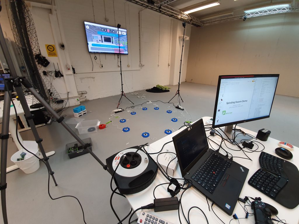
Last Wednesday we had our first live tutorial event, explaining our Spiral Swarm Demo that we usually show at conferences. About 60 people signed up and it seems that we have about 40-50 people that were able to join from all parts of the world. There were even several Crazyflie users from Asia that stayed up late especially for this, so we definitely appreciated the dedication!
For those who missed it, you can find the recordings and slides on this event page.
The Tutorial
The first hour we were mostly talking about the Lighthouse positioning system and in particular focusing on the base station V2. In real time, we had hands-on sessions where we actually showed how we setup the system, how to retrieve the calibration data and how to achieve geometry. The hour ended with showing a Crazyflie flying in the lighthouse system itself.
After the break , we focused on how to achieve more autonomy in the swarm, where we talked about the limitation of communication, the high level commander and the app layer. This was also shown with hands-on with multiple flying Crazyflies and the full automatic demo at the end. We were able to keep showing the demo in the end for a 30 minutes more while we were resting up with a drink :)
We were using Discord and Mozilla Hubs simultaneously to stream the tutorial. Discord worked out nicely since we could have one channel for the stream and one channel for the chat, which one of us was able to look at continuously. Mozilla hubs was a nice add-on however it definitely had some hiccups and streaming quality issues, which is not ideal for following a tutorial. Also being in Virtual Reality for 2 hours is very exhausting we heard from headset-using participants.
What next?
We really liked doing the tutorial and speaking one-on-one with our users very much so we are likely to organize one again. Not sure at what frequency though but of course we will announce it first. We have already some requests for topics so we will look into those first. Next time it probably will be a shorter tutorial on Discord only. Mozilla Hubs might still be used but as a virtual gallery where we put 3D visualizations of what we are working on (like how the base station sweeps work for instance), so that people can get a better understanding. If you have any request for topics please leave a comment below.
We will also try out to use our new Discord Server as a digital ‘watering hole’ for our users. Here everybody will have the opportunity to chat with each-other, to share awesome projects and to maybe help each-other out with certain questions. However, we will not be on Discord ourselves all the time and still advise to use forum.bitcraze.io as the main place to ask questions and to seek for support.