Blog

When designing flying robots like drones it is important to be able to benchmark and test the propulsion system which in this case is a speed controller, motor and propeller. As we at Bitcraze are mainly working with tiny drones we need a thrust stand designed for small motors and propellers. We have actually already designed our own system identification deck, which can measure overall efficiency, thrust, etc., but is lacking the ability to measure torque. Torque is needed to be able to measure propeller efficiency which is now something we would like to measure. Before we developed the system-id deck we searched for of the shelf solutions that could satisfy our needs and could not find any. This still seems true, please let us know if that isn’t the case.

Expanding the system-id deck to measure torque doesn’t work and building something from scratch was a too big of a project for us. Next natural option would then be to modify an existing thrust stand and our choice fell for the tyro robotics 158X series.

Looking at specifications, images and code we could figure out that replacing the load cells for more sensitive ones should be possible. The stock setup of 5kgf thrust and 2Nm of torque is just too much as we are looking for around 100 grams of thrust and around 10 mNm of torque. So we decided to give the replacement of load cells a shot! Assembly was quite smooth but we managed to break one of the surface mount load cell connectors off, luckily this was easily fixable with a soldering iron. With the stock setup we did some measurements with a 0802 11000KV brushless motor and a 55mm propeller in a pushing setup. It works but the measurements are noisy and repeatability is not great. Next thing would be to replace the load cells. The 158X uses TAL221 sized load cells which are available down to 1kg. We got those and with a calibration-allways-pass code we got from Tyto robotics we could make the calibration pass (note that modifying the thrust stand breaks the warranty). Now the thrust stability was much better but still the torque was a bit to noisy. We decided to go for even smaller thrust cells, the TAL220, and build 3D printable adapters to make them fit.

Now the torque noise level looked much better and so did the repeatability. By empirically measuring the thrust and torque using calibrated weights and by checking the measurements in RCBenchmark we got these values:

Thrust, calibrated weight [g]Measured [g]Noise [g]
2002001
1001001
50500.5
20200.5
10100.5
000.5
Trust (calibrated using 200g weight)
Torque, calibrated weight [g]Measured [mNm]Noise [mNm]
2002572
1001281
50640.3
2025.70.3
1012.70.3
000.2
Torque (calibrated using 200g weight)
Simple repeatability test

The thrust stand modification is still very fresh and we have to figure out some things but it all looks promising. For example we get 13% less overall efficiency when measuring it using our system-id thrust stand. Our guess is that it is due to that the Crazyflie arms in the system-id case blocks the airflow.

If you would like to do this modification yourself there are some simple instructions and STL files over at out mechanical github repository. Have fun!

I talked about it here already in October, but there is a lot we want to do here at Bitcraze- and not enough people to do it. So, we’re still looking for a new team member! You can read more about our requirements here; if you’re a polyvalent developer interested in hardware, with an open mind and the willingness to move to Malmö, don’t hesitate to apply by sending us an email: job@bitcraze.se.

We’ve actually also started the search for another job. But first a little background: each morning, on Mondays, Wednesdays, and Thursdays, we pack and ship our orders. Someone takes 1, 2, or even 3 hours to make sure every order passes the door. In 2022, the median time between when you would buy our products and the moment it’s shipped was 1 day. It’s something that is usually common in a big company with a whole warehouse and a team dedicated to that… But at Bitcraze, the warehouse is actually a space in our flight arena and we’re only 6 people. To have more time for development, we’re now looking for someone, ideally a student, to help us out a few hours a week packing and shipping. So if you happen to know anyone near Malmö that fits the description, send him this blog post!

And, since I don’t want to tell you the same thing that I talked about in my last blog post, and it’s International Worker’s Day, I’ve decided to make an extremely subjective list of all the awesome advantages there are working at Bitcraze. So here are perks that you get at Bitcraze that you’ll get nowhere else:

  • The flexibility to do what you’re most passionate about, and the encouragement to do so. You love printers? RUST? You get excited talking about a new LED or cool stickers? You’ll get the opportunity to fulfill your geekiest dream here (those are all examples I’ve witnessed)
  • The occasion to actually shape the company we’re working in. Your interests, your passions, and your knowledge will find their place and you’ll have the possibility to make decisions on the future of Bitcraze even after the first day- my first day working here was at a quarterly meeting where we decided on a lot of things I didn’t even understood yet.
  • Fun Fridays, where you get to work on whatever you fancy; one day a week where productivity is not a demand and you can just get going on creating the newest prototype – and if it doesn’t work, at least you learned something!
  • A demo every 2 weeks, where you can actually be impressed by a blinking LED (again, true story; and it was really impressive)
  • Awesome colleagues that will almost never steal the stuff on your desk (unless Kristoffer labels it, which is now known as the “please borrow me” label)
  • Falafel Tuesdays – when you can debate which is the best falafel in town while eating the best falafel in town.
  • Sometimes, there is karaoke or VR games or bowling – we usually invent a pretext to enjoy some after-work together.
  • Daily inspiration both from the way we work but also the awesome stuff people do with our products.
  • The occasion to learn at least a new thing a day – wether it’s how your body reacts to sugar, how FedEx handles the taxes in Japan or what is the best way to make your Crazyflie make a loop.
  • While this is not Bitcraze-specific, the Swedish coast – kind of like Palm Beach without the heat (and the palms) and the general nature surrounding Malmö. Or if you don’t like nature, the possibility to enjoy a big city (Copenhagen, across the bridge) while living in a quiet area.

I hope I picked your interest, or at least gave you some insights on what it’s really like to work at Bitcraze!

It is easy to forget that the reason why it is nice to develop for the Crazyflie is because it weighs only about 30 grams. In case something goes wrong with your script or there is a fly-away, you can simply pick it up from the air without worrying about the propellers hitting you. Moreover, when the Crazyflie crashes, it usually only requires a brush off and a potential replacement of a motor-mount or propeller. The risk of damage to yourself, other people, indoor furniture, or the vehicle itself is extremely low. However, things become very different if you’ve built a larger platform with the Bolt or BQ deck with large brushless motors (like with this blogpost), where the risk of injury to people or to the vehicle itself increases significantly. That is one of the major reasons why the BQ deck and the Bolt are still in early access and have been for a while. In our efforts to get it out of early access, it’s time to start thinking about safety features.

In this blog post, we’ll be discussing how other open-source autopilot programs are implementing safety features, followed by a discussion on current efforts for Crazyflie, along with an announcement of the developer meeting scheduled for May 3rd (see below for more info).

Catching the Crazyflie with a net

Safety in other Autopilots

We are a bit late to the game in terms of safety compared to other autopilot programs such as PX4, ArduPilot, Betaflight and Paparazzi UAV, which have been thinking about safety for quite some time. It makes a lot of sense when you consider the types of platforms that run these autopilots, such as large fixed VTOL or fixed-wing vehicles or 10-kilo quadcopters with cinematic cameras, or the degree of outdoor flight regulation. Flying a UAV autonomously or by yourself has become much more challenging as the US, EU, and many other countries have made it more restrictive. In most cases, you are not even allowed to fly if fail-safes are not implemented, such as what to do if your vehicle loses GPS signal. These types of measures can be separated into pre-flight checks and during-flight checks.

Pre-flight checks

Before a vehicle is allowed to fly, or even before the motors are allowed to spin, which is called ‘arming’, several conditions must be met. First, it needs to be checked if all internal sensors, such as the IMU, barometer, and magnetometer, are calibrated and functional, so they don’t give values outside of their normal operating range. Then, the vehicle must receive a GPS signal, and the internal state estimator (usually an extended Kalman filter) should converge to a position based on that information. It should also be determined if an external remote control is connecting to the vehicle and if there is any datalink to a ground station for telemetry. Feasibility checks can also be implemented, such as ensuring that the mission loaded to the UAV is not outside its mission parameters or that the start location is not too far away from its take-off position (assuming the EKF is functional). Additionally, the battery should not be low, and the vehicle should not still be in an error state from a previous flight or crash.

All of these features have the potential to be turned off or made less restrictive, depending on your situation. However, keep in mind that changing any of these may require recertification of the drone or make it fall outside what is required for outdoor flight regulation. Therefore, these should only be changed if you know what you are doing.

Preflight checks documentation

Fail-safe triggers during flight

Now that the pre-flight checks have passed, the UAV is armed and you have given it the takeoff command. However, there is so much more that can go wrong during a UAV flight, and takeoff is one of the most dangerous moments where everything could go wrong. Therefore, there are many more safety features, aka failsafes, during the flight than for the pre-flight checks. These can also be separated into ‘triggers’ and ‘behaviors,’ so that the developer can choose what the UAV should do in case of a failure, such as ‘GPS loss’ to ‘land safely’ and so on.

Thus, there are triggers that can enable the autopilot’s failsafe mechanics:

  • No connection with the remote control
  • No connection with the Ground station or Datalink
  • Low Battery
  • Position estimate diverges or full GPS loss
  • Waypoint going beyond geofence or Mission is not feasible
  • Other vehicles are nearby.

Also, sometimes the support of an external Automatic Trigger system is required, which is a box that monitors the conditions where the UAV should take action in case there is no GPS, other aerial vehicles are nearby, or the UAV is crossing a geofence determined by outdoor flight restrictions. Note that all of these triggers usually have a couple of conditions attached, such as the level of the ‘low battery’ or the number of seconds of ‘GPS loss’ deemed acceptable.

Fail-safe behavior

If any of the conditions mentioned above are triggered, most autopilot suites have some failsafe behaviors linked to those set by default. These behaviors can include the following:

  • No action at all
  • Warning on the console or remote control display
  • Continue the mission autonomously
  • Stay still at the same position or go to a home position
  • Fly to a lower altitude
  • Land based on position or safely land by reducing thrust
  • No input to motors or completely disarming the motors

Usually, these actions are set in regulation, but per trigger, it is possible to give a different behavior than the default. One can decide to completely disarm the vehicle, but then the chances of the UAV crashing are pretty high, which can result in damage to the vehicle or cause harm to people or objects. By the way: disarming is the opposite act of arming, which is not allowing the motors to spin, no matter if it is receiving an input. If you decide to never do anything and force the drone to finish the mission autonomously, then in a case of GPS or position loss, you risk losing your vehicle or that it will end up in areas where it is absolutely not allowed, such as airports. Again, changing these default behaviors should be done by someone who knows what they are doing, and it should be done with careful consideration.

Failsafe documentation other autopilot suites:

Emergencies

Fail-safes are measures that ensure safe flight. However, there will always be a chance that an emergency will occur, which will require an immediate action as well. If the vehicle has crashed during any of its phases or has flipped, or if the hardware breaks, such as the motors, arms, or perhaps even the autopilot board itself, what should be done then?

The standard default behavior for this is to completely disarm the vehicle so that it won’t react to any input to the motors itself. Of course, it’s difficult to do if the autopilot program is on, but at least it won’t try to take off and finish its mission while laying on its side. It might be that a backup system is connected to the ESCs that will take over in case the autopilot is not responding anymore, perhaps using a different channel of communication.

Also, the most important safety feature of all is the pilot itself. Each remote control should have a special button or switch that can put the drone in a different mode, make it land, or disarm it so that the pilot can act upon what they see. In case the motors are still spinning, have a net or towel available to throw over them, disconnect the battery as soon as possible, and make sure to have sand or a special fire retardant in case the LiPo batteries are pierced.

All of the autopilots have some tips to deal with such situations, but make sure to do some good research yourself on how to handle spinning parts or potential LiPo battery fires. I’m just giving a compilation of tips given in the documentation above here, but please make sure to read up in detail!

Safety in the Crazyflie Firmware

So how about the Crazyflie-firmware ? We have some safety features build in here and there but it is all over the code base. Since the Crazyflie is so safe, there was no immediate need for this and we felt it is more up to the developer to integrate it themselves. But with the Bolt and BQ deck coming out of early access, we want to at least do something. As we started already started looking into how other autopilot softwares are doing it, we can get some ideas, however we did notice that many of these are mostly meant for outdoor flight. The Crazyflie and the Crazyflie Bolt have been designed for indoor use and perhaps deal with different issues as well.

Current safety features

This is a collection of safety features currently in the firmware at the time of writing this blogpost. Most safety features in the Crazyflie are up for the developer to double check before and during flight, but these are some automatic once that are scattered around the firmware:

However, if for instance your Crazyflie or Bolt platform loses its positioning in air, or doesn’t have a flowdeck attached before takeoff, there are no default safety systems in check. You either need to catch it, make it land or use an self-made emergency stop button using one of the emergency stop services above.

Safety features in works

As mentioned earlier, we have safety features spread throughout the code base of the Crazyflie firmware. Our current effort is to collect all of these emergency stops and triggers in the supervisor module to have them all in one place.

In addition, since indoor positioning is critical, we want to be notified when it fails. For instance, if the lighthouse geometry is incorrect, we need to see if the position diverges. This check was done outside of the Crazyflie firmware in a cflib script, but it has not been implemented inside the firmware. We also want to provide some options in terms of behavior for these triggers. Currently, we are working on two options: ‘turn the motors off’ or ‘safe land,’ with ‘safe land’ decreasing the thrust while keeping the drone level in attitude.

Furthermore, we want to integrate these features into the cfclient as well. For example, we want to add more emergency safety features to our remote control through the cfclient, and show users how to arm and disarm the vehicle.

These are the elements we are currently working on, but there might be more to come!

Developer meeting May 3rd

You probably already guessed it… the topic about the next developer meeting will be about the safety features in the Crazyflie and the Bolt! We will present the current safety features in the Crazyflie and what we are currently working on to make it better. In this sense, we really want to have your feedback on what you think is important for brushless versions of the Crazyflie for indoor flight!

The Dev meeting will be on Wednesday May the 3rd at 3 PM CEST. Please keep an eye on the discussion forum in the developer meeting thread.

Today, our guest Airi Lampinen from Stockholm University is presenting the second Drone Arena Challenge. Enjoy!

Welcome to the second Drone Arena Challenge, a one-of-a-kind interactive experience with Bitcraze’s Crazyflie! This year, the challenge is focused on moving together with drones in beautiful, curious, and provocative ways – without needing to write a single line of code!

Moving with drones. Image credit: Rachael Garrett.

What, when, where? The event takes place May 16-17, 2023 at KTH’s Reactor Hall in Stockholm – a dismantled nuclear reactor hall – which provides a unique setting for creative human–drone encounters. You don’t need your own drone or be able to program a drone to participate! We will provide the drone equipment (a Crazyflie 2.1 equipped with the AI-deck) and take care of everything necessary to make them fly. What you need to do is to be creative and move together with the drones to set up the best show you can deliver! There’ll be a jury judging the final performances and we have exciting prizes for the most successful teams!

Drone Arena in the Reactor Hall. Picture from the first challenge, held in June 2022. Picture credit: Fatemeh Bakhshoudeh

Who can join? Anyone irrespective of training, profession, and past experience with drones or performing arts is welcome to participate. Participants need to be at least 18 years old. If you are curious about how technology and humans may play together, enthusiastic about the Crazyflie, or eager to learn how to move with the Crazyflie, this event is for you. We welcome up to 10 pairs (teams of 2 people) to participate in the challenge.

Registration is already open, with only a few spots remaining. We encourage those interested to sign up as soon as possible to secure their spot!

Program & prizes? On the first day of the hackathon, we will host a keynote speaker and a short information session to explain what participants are expected to do and what support is available for them. The teams will then have access to the Reactor Hall to work on the challenge and explore moving with their drone – we offer long hours but each team is free to choose how much they want to work. (The goal here is to have a good time!) The competition itself takes place on the second day. We’ve got exciting prizes for the most successful teams!

Read more about the challenge, the prizes, and how to sign up on our website: http://www.dronearena.info/

The event is organized as a part of the Digital Futures demonstrator project Digital Futures Drone Arena led by Luca Mottola from RISE and Airi Lampinen from Stockholm University.

As you might have noticed, most of our bundles are currently unavailable because Crazyradio PA is out of stock. We are currently finishing the production for the Crazyradio PA replacement, Crazyradio 2.0 which means that, if everything continues to go well, it should be in stock and ready to ship in a couple of weeks.

One of the first produced Crazyradio 2.0
One of the first produced unit of Crazyradio 2.0, fresh out of a successful run in the test rig

Crazyradio 2.0 is designed to be a drop-in replacement for Crazyradio PA as well as an improvement that will allow new development and improvement for the communication with Crazyflie(s). Among the hardware change we have:

  • Much more powerful microcontroller: the nRF52840, a Cortex-M4 at 64MHz, 1MB of Flash, 256KB of ram with a much more flexible 2.4GHz radio hardware compared to Crazyradio PA.
  • Safe and easy to use Bootloader with button to launch it for easy upgrade
  • RGB LED for richer status indication
  • The same SWD debug port as on the Crazyflie 2.0 for easy development and debugging
  • As on Crazyradio PA, a radio power amplifier with a 20dBm (100mW) output power
  • Only support 1Mbit/s and 2MBit/s bitrate (Crazyradio PA also supported 250Kbit/s)

The improved microcontroller and safe and easy to use bootloader are the most important as they will allow us to experiment and implement new radio protocols over time. Things like peer-to-peer protocols, channel hopping and link cryptographic protection are now possible to work on.

All these new functionalities will come later though. So far we have been really hard at work to get the hardware ready and out as a Crazyradio PA replacement. To achieve that goal we have developed two version of the Crazyradio 2.0 firmware:

  • The Crazyradio2 firmware that implements the same radio protocol as the Crazyflie 2.0 but has a new improved USB protocol that improves performance and allows for the development of new radio protocols. It will also not require any driver on Windows.
  • The Crazyradio2-crpa-emulation firmware that emulates a Crazyradio-PA USB and Radio protocol. This version of the firmware allows to use the Crazyradio 2.0 with any client that supports Crazyradio PA.

Since support for the new USB protocol is not implemented in any clients yet, we are shipping the Crazyradio 2.0 in bootloader mode. When plugged in a computer for the first time, Crazyradio 2.0 will appear as a USB disk drive:

Clicking on README.HTM will open the web-browser to the Bitcraze website page that lists both available firmware with explanations of which one to choose. At first the CRPA-emulation firmware will likely be the most useful but over time the new Crazyradio2 protocols will be the best choice. Once the firmware downloaded it can just be drag-and-dropped in the Crazyradio 2 drive and the radio will restart in firmware mode and be ready to use!

Pressing the button on the Crazyradio when inserting it in the PC will launch the bootloader again and we are planing on making future updates possible via the Crazyflie clients as well. This is an exciting time as we will now be much more free to experiment, iterate and eventually greatly improve the communication capabilities of Crazyradio as well as of the Crazyflie quadcopters!

Now for the more practical information: if everything goes well Crazyradio 2.0 will be available in the bitcraze store the last week of April 2023, we are going to sell it for 40 USD. This means that most bundles should also be back in stock with Crazyradio 2.0 replacing Crazyradio PA in the bundles.

This week’s guest blogpost is from Matěj Karásek from Flapper Drones, about flying the Nimble + with a positioning system. Enjoy!

Flapper Drones are bioinspired robots flying by flapping their wings, similar to insects and hummingbirds. If you haven’t heard of Flappers yet, you can read more about their origins at TU Delft and about how they function in an earlier post and on our company website.

In this blogpost, I will write about how to fly the Flappers (namely the Flapper Nimble+) autonomously within a positioning system such as the Lighthouse, and will of course include some nice videos as well.

The Flapper Nimble+ is the first hover-capable flapping-wing drone on the market. It is a development platform powered by the Crazyflie Bolt and so it can enjoy most of the perks of the Crazyflie ecosystem, including the positioning systems as well as other sensors (check this overview). If you would like to get a Flapper yourself, just head to the Bitcraze webstore, where there are some units ready to be shipped! (At the time of writing at least…)

Minimal setup

The minimal setup for flying in a positioning system is nearly identical as with a standard Crazyflie. Next to a Flapper with a recent firmware, a Crazyradio dongle, a positioning system (in this post we will use the Lighthouse), and a compatible positioning deck (Lighthouse deck) you will also need: 1) a mount, such that the deck can be attached on top of the Flapper, and 2) a set of extension cables. You can 3D print the mounts yourself (models here), the extension cable prototypes can either be inquired from Flapper Drones, or can be soldered by yourself (in that case, the battery holder deck, standard Crazyflie pin headers and some wires come handy). Just pay attention to connect the cables in the correct way, as if the deck was mounted right on top of the Bolt. The complete setup with the Lighthouse deck will look like this:

Lighthouse deck installation on a Flapper Nimble+. Make sure the extension cables are well secured (e.g. by using the additional cable mount) such they don’t get caught by the gears.

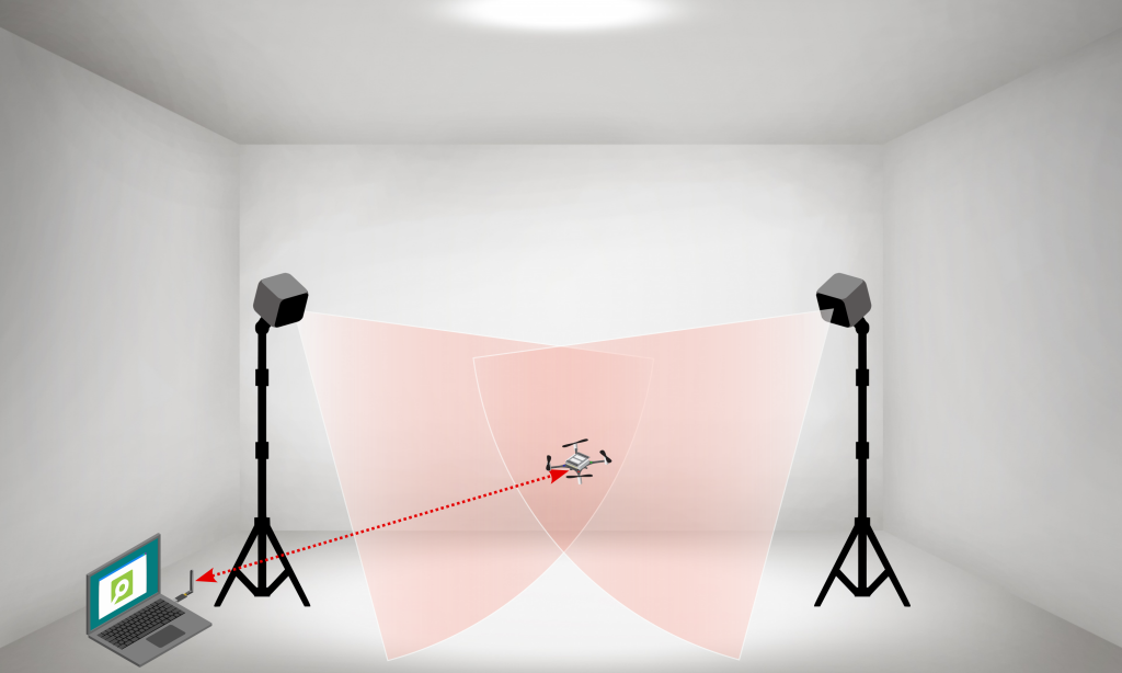
For the Lighthouse, as with regular Crazyflies, the minimum number of base stations (with some redundancy) is 2, but you will get larger tracking volume with more base stations. 4 base stations mounted at 3 m height will give you about 5 meters time 5 meters coverage, which is recommended especially if you want to fly more than 1 Flapper at a time (they are a bit larger than the Crazyflies, after all…).
From now on, it is exactly the same as with standard Crazyflies. After you calibrate the Lighthouse system using the standard wizard procedure via the Cfclient, you can just go to the Flight Control Tab and use the “Command Based Flight Control” buttons to take-off, command steps in xyz directions and land. It is this easy!

Flapper Nimble+ in Lighthouse flown via Command Based Flight Control of cfclient

Assisted flight demo

We used this setup in February for the demos we were giving at the Highlight Delft festival in the Netherlands. This allowed people with no drone piloting skills (from 3-year-olds, to grandmas – true story) fly and control the Flapper in a safe way (safe for the Flapper, as the Flapper itself is a very safe platform thanks to its soft wings and low weight). To make it more fun, and even safer for the Flapper, we used a gamepad instead of on screen buttons, and we modified the cfclient slightly such that the flight space can be geofenced to stay within the tracking volume.

Flight demo at Highlight Delft festival, using the Lighthouse and position hold assistance

If you would like to try it yourself (it works also with standard crazyflies), the source code is here (just keep in mind it is experimental and has some known bugs…). To fly in the position-assisted mode, you need to press (and keep pressing) the Alt 1 button, and use the joysticks to move around (velocity commands, headless mode). Releasing the Alt 1 button will make the Flapper autoland. Autoland will also get triggered when the battery is low. You can still fly the Flapper in a direct way when pressing Alt 2 instead.

Flying more Flappers at a time

Again, this is something that works pretty much out of the box. As with a regular crazyflie, you just need to assign a unique address to each of the Flappers and then use e.g. this example python script to run a preprogrammed sequence.

With a few extra lines of code, we pulled this quick demo at the end of the Highlight Delft festival, when we had 30 minutes left before packing everything (one of the Flappers decided to drop its landing gear, probably too tired after 3 evenings of almost continuous flying…):

Sequence with 3 Flappers within Lighthouse positioning system

Other positioning systems

Using other positioning systems is equally easy. In fact, for the Loco Positioning system, the deck can even be installed directly on the Flapper’s Bolt board (no extension cables or mounts are needed). As for optical motion tracking, we do not have experience with Qualisys and the active marker deck, but flying with retro-reflective markers within OptiTrack system can be setup easily with just a few hacks.

When choosing and setting up the positioning system, just keep in mind that due to its wings, the Flapper needs to tilt much more to fly forward or sideways, compared to a quadcopter. This is not an issue with the Loco Positioning system (but there can be challenges with position estimation, as described further), but it can be a limitation for systems requiring direct line of sight, such as the Lighthouse or optical motion tracking.

Ongoing work

In terms of control and flight dynamics, the Flapper is very different from the Crazyflie. Thus, for autonomous flight, there remains room for improvement on the firmware side. We managed to include the “flapper” platform into the standard Crazyflie firmware (in master branch since November 2022, and in all releases since then), such that RC flying and other basic functionality works out of the box. However, as many things in the firmware were originally written only for a (specific) quadcopter platform, the Crazyflie 2.x, further contributions are needed to unlock the full potential of the Flapper.

With the introduction of “platforms” last year, many things can be defined per platform (e.g. the PID controller gains, sensor alignment, filter settings, etc.), but e.g. the Extended Kalman filter, and specifically the motion model inside, has been derived and tuned for the Crazyflie 2.x, and is thus no representative of the Flapper with very different flight dynamics. This is what directly affects (and currently limits) the autonomous flight within positioning systems – it works well enough at hover and slow flight, but the agility and speed achievable in RC flight cannot be reached yet. We are planning to improve this in the future (hopefully with the help of the community). The recently introduced out of tree controllers and estimators might be the way to go… To be continued :)

Thanks Matej ! And for those of you at home, don’t forget that we have our dev meeting next Wednesday (the 5th), where we’ll discuss about the Loco positioning system, but also will take some time for general discussions. We hope to see you there!

In this blog post we will take a look at the new Loco positioning TDoA outlier filter, but first a couple of announcements.

Announcements

Crazyradio PA out of stock

Some of you may have noticed that there are a lot bundles out of stock in our store, the reason is the transition from Crazyradio PA to the new Crazyradio 2.0. Most bundles contain a radio and even though the production of the new Crazyradio 2.0 is in progress, the demand for the old Crazyradio PA was a bit higher than anticipated and we ran out too early. Sorry about that! We don’t have a final delivery date for the Crazyradio 2.0 yet, but our best guess at this time is that it will be available in about 4 weeks.

Developer meeting

The next developer meeting is on Wednesday, April 5 15:00 CEST, the topic will be the Loco positioning system. We’ll start out with around 30 minutes about the Loco Positioning system, split into a presentation and Q&A. If you have any specific Loco topics/questions you want us to talk about in the presentation, please let us know in the discussions link above.

The second 30 minutes of the meeting with be for general support questions (not only the Loco system).

The outlier filter

When we did The Big Loco Test Show in December, we found some issues with the TDoA outlier filter and had to do a bit of emergency fixing to get the show off the ground. We have now analyzed the data and implemented a new outlier filter which we will try to describe in the following sections.

Why outlier rejection

In the Loco System, there are a fair amount of packets that are corrupt in one way or the other, and that should not be part of the position estimation process. There are a number of reasons for errors, including packet collisions, interference from other radio systems, reflections, obstacles and more. There are several levels of protection in the path from when an Ultra Wide Band packet is received in the Loco Deck radio to the state estimator, that aims at removing bad packets. It works in many cases, but a few bad measurements still get all the way through to the estimator, and the TDoA outlier filter is the last protection. The result of an outlier getting all the way through to the estimator is usually a “jump” in the estimated position, and in worst case a flip or crash. Obviously we want to catch as many outliers as possible to get a good and reliable position estimate and smooth flight.

The problem(s)

The general problem of outlier rejection is to decide what is a “good” measurement and what is an outlier. The good data is passed on to the state estimator to be used for estimating the current position, while the outliers are discarded. To decide if a measurement is good or an outlier, it can be compared to the current position, if it is “too far away” it is probably an outlier and is rejected. The major complication is that the only knowledge we have about the current position is the estimated position from the state estimator. If we let outliers through, the estimated position will be distorted and we may reject good data in the future. On the other hand if we are too restrictive, we may discard “good” measurements which can lead to the estimator loosing tracking and the estimated position drift away (due to noise in other sensors). It is a fine balance as we use the estimated position to determine the quality of a measurement, at the same time as the output of the filter affects the estimated position.

Another group of parameters to take into account is related to the system the Crazyflie and Loco deck are used in. The over all packet rate in a TDoA3 system is changed dynamically by the anchors, the Crazyflie may be located in a place where some anchors are hidden, or the system may use the Long Range mode that uses a lower packet rate. All these factors change the packet rate and his means that the outlier filter should not make assumptions about the system packet rate. Other factors that depend on the system is the physical layout and size, as well as the noise level in the measurements, and this must be handled by the outlier filter.

In a TDoA system, the packet rate is around 400 packets/s which also puts a requirement on resource usage. Each packet will be examined by the outlier filter, why it should be fairly light weight when it comes to computations.

Finally there are also some extra requirements, apart from stable tracking, that are “nice to have”. As a user you probably expect the Crazyflie to find its position if you put it somewhere on the ground, without having to tell the system the approximate position, that is a basic discovery functionality. Similarly if the system looses position tracking, you might expect it to recover as soon as possible, making it more robust.

The solution

The new TDoA outlier filter is implemented in outlierFilterTdoa.c. It is only around 100 lines of code, so it is not that complex. The general idea is that the filter can open and close dynamically, when open all measurements are passed on to the estimator to let it find the position and converge. Later, when the position has stabilized, the filter closes down and only lets “good” measurements through. In theory this level of functionality should be be enough, after the estimator has converged it should never lose tracking as long as it is fed good data. The real world is more complex, and there is also a feature that can open the filter up again if it looks like the estimator is diverging.

The first test in the filter is to check that the TDoA value (the measurement) is smaller than the distance between the two anchors involved in the measurement. Remember that the measurements we get in a TDoA system is the difference in distance to two anchors, not the actual distance. A measurement that is larger than the distance between the anchors is not physically possible and we can be sure that the measurement is bad and it is discarded.

The second stage is to examine the error, where the error is defined as the difference between the measured TDoA value and the TDoA value at our estimated position.

float error = measurement - predicted;

This error does not really tell us how far away from the estimated position the measurement is, but it turns out to be good enough. The error is compared to an accepted distance, and is considered good if it is smaller than the accepted distance.

sampleIsGood = (fabsf(error) < acceptedDistance);
The area between the blue and orange lines represents the positions where the error is smaller than some fixed value.

The rest of the code is related to opening and closing the filter. This mechanism is based on an integrator where the time since the last received measurement is added when the error is smaller than a certain level (integratorTriggerDistance), and remove if larger. If the value of the integrator is large, the filter closes, and if it is smaller than a threshold it opens up. This mechanism implements a hysteresis that is independent on the received packet rate.

The acceptedDistance and integratorTriggerDistance are based on the standard deviation of the measurement that is used by the kalman estimator. The idea is that they are based on the noise level of the measurements.

Feedback

The filter has been tested in our flight lab and on data recorded during The Big Loco Test Show. The real world is complex though and it is hard for us to predict the behavior in situations we have note seen. Please let us know if you run into any problems!

The new outlier filter was pushed after the 2023.02 release and is currently only available on the master branch in github (by default). You have to compile from source if you want to try it out. If no alarming problems surface, it will be the the default filter in the next release.

We are excited to announce that we will be having developer meetings on first Wednesdays of every month! Additionally, we are thrilled to be present in person at ICRA 2023 in London. During the same conference, there will be half day workshop called ‘The Role of Robotics Simulators for Unmanned Aerial Vehicles’ so make sure to sign-up! Please check out our newly updated event-page !

Monthly Developer meetings

We have had some online developer meetings in the past covering various topics. While these meetings may not have been the most popular, we believe it is crucial to maintain communication with the community and have interesting discussions, and exchange of ideas. However, we used to plan them ad-hoc and we had no regularity in them, which sometimes caused some of us **cough** especially me **cough**, to create confusion about the timing and location. To remove these factors of templexia (dyslexia for time), we will just have it simply on the first Wednesday of every month.

So our first one with be on Wednesday 5th of April at 15:00 CEST and the information about the particular developer meeting will be as usual on discussions. From 15:00 – 15:30 it will be a general discussion, probably with a short presentation, about a topic to be determined. From 15:30-16:00 will address regular support question from anybody that need help with their work on the Crazyflie.

ICRA 2023 London

ICRA will be held in London this year, from May 29 – June 2nd, atthe ExCel venue. We will be located in the H11 booth in the exhibitor hall, but as the date approaches, we will share more about what awesome prototypes we will showcase and what we will demonstrate on-site. Rest assured, plenty of Crazyflies will be flown in the cage! To get an idea of what we demo-ed last year it IROS Kyoto, please check out the IROS 2022 event page. Matej from Flapper Drones will join us at our booth to showcase the Flapper drone.

We are thinking of organizing a meetup for participants on the Wednesday after the Conference Dinner, so we will share the details of that in the near future as well. Also keep an eye on our ICRA 2023 event page for updated information.

ICRA Aerial Robotic Simulation Workshop

I (Kimberly) will also be present at the ‘The Role of Robotics Simulators for Unmanned Aerial Vehicles‘ workshop on Friday June 2nd. Together with Giuseppe Silano, Chiara Gabellieri and Wolfgang Hönig, we will be organizing a half day workshop focused on UAV-specific simulation in robotics. We have invited some great speakers namely: Tomáš Báča, Davide Scaramuzza, Angela Schoellig and Jaeyoung Lim. The topics will cover multi-YAV simulation to realistic vision-based rending and software-in-the-loop handling for PX4.

Additionally, participants can submit an extended abstract to be invited for an poster presentation during the same workshop. The submission deadline has been extended to April 3rd, so for more information about submission, schedule and speaker info, go to the workshop’s website.

This week’s guest blogpost is from Florian Goralsky from Bok o Bok about their dance piece with multiple Crazyflies. Enjoy!

Flying bodies across the fields is a contemporary dance piece for four performers and a swarm of drones, exploring the phenomenon of the disappearance of bees and the use of pollinating drones to compensate for this loss. The piece attempts to answer this crucial question in a poetical way: can the machine create life and save us from ecological disaster?

Novembre Numérique à l’IFCI © M studio

We’re super excited to talk about a performance that we’ve been working on for the past two years in collaboration with Bitcraze. It premiered at the Environmental Forum, Centre Pompidou Paris, in 2021, and we’ve had the opportunity to showcase it at different venues since then. We are happy to share our thoughts about it!

Choreographic research

Beyond symbolizing current attempts to use drones to pollinate fields, the presence of the Crazyflie drones, supports the back and forth between nature and technology. We integrate a swarm, performing complex choreographies, which refer to the functioning of a beehive, including the famous “bee dance”, discovered by Karl von Frisch, which is used to transmit information on the food sources. Far from having a spectacular performance as its only goal, the synchronization of autonomous drones highlights bio-inspired computer techniques, focused on collective intelligence.

© bok o bok

Challenges within a dance performance

Making a dance performance with drones needs a high accuracy and adaptability, both before and during the show. Usually, we only have a few hours, sometimes even a few minutes, to setup the system according to the space. We quickly realized we needed pre-recorded choreographies, and hybrid choreographies where the pilot could have a few degrees of freedom on pre-defined behaviors.

GUI Editor + Python Server

Taking this into account, we developed a web GUI editor, that is able to send choreographies created with any device to a Websocket Python server. The system supports any absolute positioning system (We use the Lighthouse), and then converts all the setpoints and actions to the Crazyflie API HighLevelCommander class. This system allows us to create, update, and test complex choreographies in a few minutes on various devices.

Preview position of six drones at a certain time.
Early support of the CompressedTrajectories format, with Cubic bezier curves.

What is next?

We are looking forward to developing more dancers-drones interactions in the future. It will imply, in addition to the Lighthouse system, other sensors, in order to open up new possibilities: realtime path-finding, obstacle avoidance even during a recorded choreography (to allow improvisation), etc.

Novembre Numérique à l’IFCI © M studio

A big part of our work is to provide examples, getting-started guides and other documentation to get users started quickly. Documentation should be up-to-date, be understandable and detailed but, at the same time, not overwhelming. Examples should cover common applications and, most importantly, teach how to create your own projects. This is a never-ending task as our eco-system constantly evolves.

In recent weeks we have updated many parts of the AI-deck documentation and examples – this process is not finished (and will never be), but we thought giving you an overview about what we think most struggle with as well as what we updated would be interesting – especially as we see many AI-deck related questions in the discussions.
We saw that many struggle with understanding the whole communication chain and the importance to update all microcontrollers in it – so we will first give an overview on how everything is connected and then dive into where to find documentation, which examples already exist and how to get started with an own project on GAP8. Note that this post is centered around the GAP8; we do not go into detail about the NINA WiFi.

Here we go:

How does the AI-deck fit into the Crazyflie Eco-System? How does it communicate?

As with all other decks, the AI-deck is connected over expansion headers. It gets power directly from the battery (VCOM), and both microcontrollers (GAP8 and the NINA WiFi module) are connected to the STM32 via UART.

AI-deck expansion header connections.

To send messages between all those microcontrollers, the CPX protocol was introduced. As the NINA and GAP8 are also connected (via SPI), we have redundant information paths – so per definition, we always route over the NINA.

Now how can we send code to the GAP8 for it to run?

GAP8 always executes code from L2 (second-level RAM), as it has no internal flash. However, it can load code into L2 over a HyperBus interface from external flash memory on startup (which it does if a fuse is blown, however this is already done on your AI-deck and out of scope here). As GAP8 has only volatile memory, it must always load code from exactly the same flash address. To make it possible to update applications easily, we implemented a bootloader, a minimal program which is the first thing to run on startup. The bootloader can either update the application code in flash or copy it into L2, and, if the code is valid, run it. Why is this easier? First, you don’t need to connect a programmer, as the bootloader can read data over other peripherals (in our case SPI from the NINA module). Second, it is safer – if the update fails (and you, for some reason, end up with random code where your application should be) the firmware code will not be valid (the hash computation will fail) and GAP8 will not jump to the corrupt application code but instead safely stay in the bootloader.

As the chain for the over-the-air update with the bootloader is rather complex, we illustrate the ways to flash GAP8 in the image below.

  • the blue path illustrates how you can program over JTAG – you can either write code directly into L2 to run it (this is volatile memory, the code will disappear if you power cycle) or you can write it into flash (over GAP8), such that it is loaded on startup (if you overwrite the bootloader, not recommended) or with the bootloader.
  • the red path is using the cfloader. Meaning it sends your code over the Crazyradio to the nRF, then further to the STM32, from there to the ESP32 (the NINA WiFi module) and from there to the GAP8. This path uses CPX messages; you can read more about it in the CPX documentation.
System Architecture of a Crazyflie with an AI-deck connected.

Where is the documentation?

We have tutorials as well as repository documentation. Tutorials guide you through all the steps needed to run a specific example, while the repository documentation aims to document the general infrastructure and examples in more detail (but without all not directly related steps such as flashing a bootloader, updating other firmware, etc.).

So when you use your AI-deck for the first time, you should start with the getting started guide.
Then you are most likely interested in a more detailed explanation about the used infrastructure, such as the GAP8 including the SDK, how to flash, which examples exist and how to run them, etc. So now you should check out the repository documentation.

As we are mostly speaking about GAP8 here, we should also mention that there is of course also documentation for it outside of Bitcraze. GAP8 is produced by Greenwaves, who provides references and has a public SDK on github – meaning one can actually look up the code for all drivers, look at open issues or even contribute with pull-requests.

Which examples exist? What are they there for? What did we update?

This example is there to get you started with your own applications – it provides a minimal implementation of how to send something to the cfclient console from the GAP8 and is explained in detail in the next section of this post.

The camera test is, as it says, to test the camera – however, it sends the image over JTAG, so if you don’t have a debugger and/or don’t want to overwrite the bootloader this is not an example for you.

The most classic example – this example is used in the getting started guide and streams video over WiFi.

This example uses filters to find faces in images – be a bit careful, though, as it is very sensitive to noisy backgrounds and, for example, blonde hair. However, along with nice image processing examples, it now also implements the streaming of the images in configurable resolution, a fun feature we recently added!

The classification demo is our AI demo which recognizes parcels. Here we recently fixed the CPX initialization, so it can again send results to the console in the cfclient!

The send character over UART example was neither updated nor tested with the newest docker (yet).

How do I write my own code on gap8?


Now we’ll walk you through a minimal example of how to send Hello World from GAP9 to the cfclient console.

C Code

We start with the main file (which we called hello_world_gap8.c and is found here) by including some dependencies:

#include "pmsis.h" for the drivers

#include "bsp/bsp.h" for some configuration parameters (pad configurations for connecting to memory, camera, etc.)

#include "cpx.h" for using the CPX functions to send our hello world to the console

Then we have to write our main function:

int main(void)
{
  return pmsis_kickoff((void *)start_example);
}Code language: JavaScript (javascript)

We call pmsis_kickoff() to start the scheduler and an event kernel, giving it a pointer to the function we want to execute.
This function is what we write next (insert it above the main function, such that it is found in the code of the main).

void start_example(void)
{
  pi_bsp_init();
  cpxInit();

  while (1)
  {
      cpxPrintToConsole(LOG_TO_CRTP, "Hello World\n");
      pi_time_wait_us(1000*1000);
  }

}Code language: JavaScript (javascript)

First we need to initialize the pads according to our configuration (the configuration is automatically chosen with sourcing the ai_deck.sh, which is automatically done in the docker) with pi_bsp_init().
Then we need to initialize CPX (which initializes for example the SPI connection to the NINA WiFi), to be able to send CPX packets. You find more information in the CPX documentation.
Now we are ready for our while loop, in which we want to send “Hello World” to the console (called LOG_TO_CRTP). To not keep the busses overly busy we only want to send it every second, so we wait before we repeat.

Makefile

The Makefile is hierarchical – meaning we have hidden files that do most of the work and need to include $(RULES_DIR)/pmsis_rules.mk in the last line of the Makefile.

We start with defining where the io should go – possibly are host or uart (this is actually not used in this example, but if you’d add a printf, this would define where it goes).
Then we define the operating system we want to use – we can use pulpos or freertos. We chose this as freertos is way more advanced (we are paying for this with some overhead, but in most cases, it will be worth it).

io=uart
PMSIS_OS = freertos

In the next step we need to set the name of our application (this defines the file names of the build output), include the sources (meaning our main c file as well as the two c files CPX needs) and include the header files directory (header files in the same directory as the Makefile should automatically found, but our CPX header files are in a library directory). Make sure all the relative paths are correct for your folder structure.

APP = hello_world_gap8
APP_SRCS += hello_world_gap8.c ../../../lib/cpx/src/com.c ../../../lib/cpx/src/cpx.c
APP_INC=../../../lib/cpx/inc

As a last step, we want to set some compiler flags. Firstly, we want to compile optimized, so we add -O3. Then we add -g to embed debug information.
As we use timers for CPX we also need to add two additional defines to ensure all functions we need are included: the configUSE_TIMERS=1 and the INCLUDE_xTimerPendFunctionCall=1 defines.

APP_CFLAGS += -O3 -g
APP_CFLAGS += -DconfigUSE_TIMERS=1 -DINCLUDE_xTimerPendFunctionCall=1

Compile and Flash


For this section we assume you are in the ai-deck-examples directory.

Now we want to compile using docker:

docker run --rm -v ${PWD}:/module --privileged bitcraze/aideck tools/build/make-example SRC_DIR clean allCode language: JavaScript (javascript)

Where SRC_DIR is the location of your code, here it is examples/other/hello_world_gap8.

Note: You don’t always need to “clean” if you don’t modify the Makefile. It should be fine to save some time by skipping this.

And finally we want to flash using the OTA updater:

cfloader flash [binary] deck-bcAI:gap8-fw -w CRAZYFLIE_URICode language: CSS (css)

Where in this example, [binary] has to be replaced with examples/other/hello_world_gap8/BUILD/GAP8_V2/GCC_RISCV_FREERTOS/target.board.devices.flash.img, and the CRAZYFLIE_URI is something like radio://0/80/2M/E7E7E7E7E7.

Now you can connect to your drone with the cfclient and should see a CPX: GAP8: Hello World print every second.

Note: The LED will not blink as in most other examples, as we did not implement a task which does this.

We hope this blog post helps you get started with your own awesome applications faster!