Last week was interrupted, disrupted and generally chopped up as a few of us had to stay home fighting germs and viruses. Today all of us were present again and hopefully we will all be well this week to participate in the fun. Even though last week will not make it to the hall of fame when it comes to productivity we still made some progress.
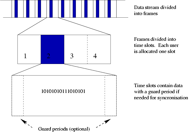
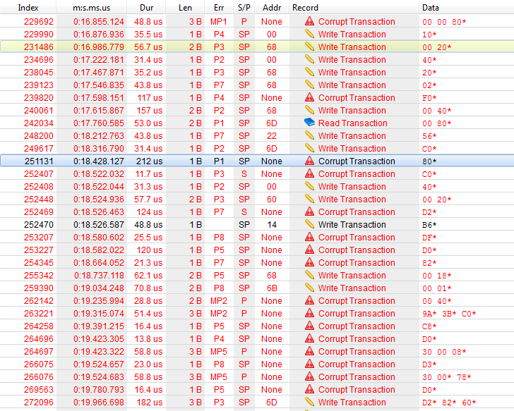
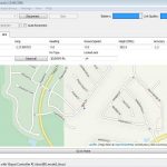
TDoA mode of the Loco Positioning system
We are happy to announce that we have calculated the first TDoA (Time Difference of Arrival) based position in the Crazyflie. This might not sound very spectacular but it is one step closer to being able to position an infinite (in theory) number of Crazyflies simultaneously. We used test driven development (TDD) to implement the functionality and we think it helped us to manage the complexity and write better code. We have written a few unit tests earlier, but this is our first serious attempt at test driven pair programming. We have based the unit tests on Unity and mocking on CMock from Throw The Switch. The result of our efforts can be seen in lpsTdoaTag.c and TestLpsTdoaTag.c.
New Logo
We have used a few different variations of logos up to now, the historical logo was good for electronic boards (PCBs) but hard to make look good in other contexts like the webpage and so we ended up in a situation where we do not have a consistent logo for everything. We have decided that we probably should try to find one that we all like and want to use everywhere. Björn has made a bunch of different designs that we all have discussed together and after a few iterations we are converging towards something really good. We will not show any previews, just stay tuned to see the final result.
The logo currently used on Bitcraze PCBs
Marcus Greiff
We want to welcome Marcus to the team, he will work with algorithms one day a week. Marcus is currently studying at LTH where he has been using the Crazyflie 2.0 platform in his studies.
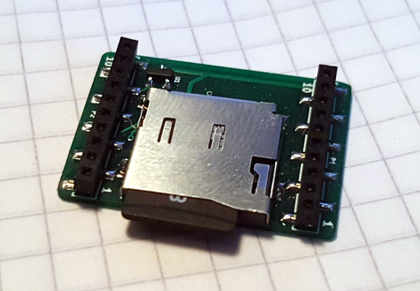
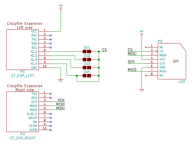
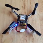
SD-card expansion deck in production
Production materials for the SD-card expansion deck has been sent to the factory. Hopefully it will be available in the shop in a few weeks time.