Today we have a guest blogpost by Simon D. Levy (Washington and Lee University) about using Haskell to warp parts of the Crazylife-firmware. We also have some announcements from Bitcraze itself at the bottom. Enjoy!
As Richard Feynman famously said, What I cannot create, I do not understand. My less ambitious version of this motto is What I can translate into another language, I might better understand.
In order to better understand the Crazyflie firmware, I first undertook to translate the C-based firmware into C++. By separating out the general-purpose algorithmic code (state estimator, closed-loop control) from the Crazyflie-specific / Hardware Abstraction Layer (HAL) component of the firmware, I ended up with a nice, header-only C++ library of algorithms that can work with both a simulator like Webots and on a Crazyflie 2.1 or Crazyflie Bolt flight controller (with the remaining Crazyflie firmware translated into the standard C++ .h/cpp format).
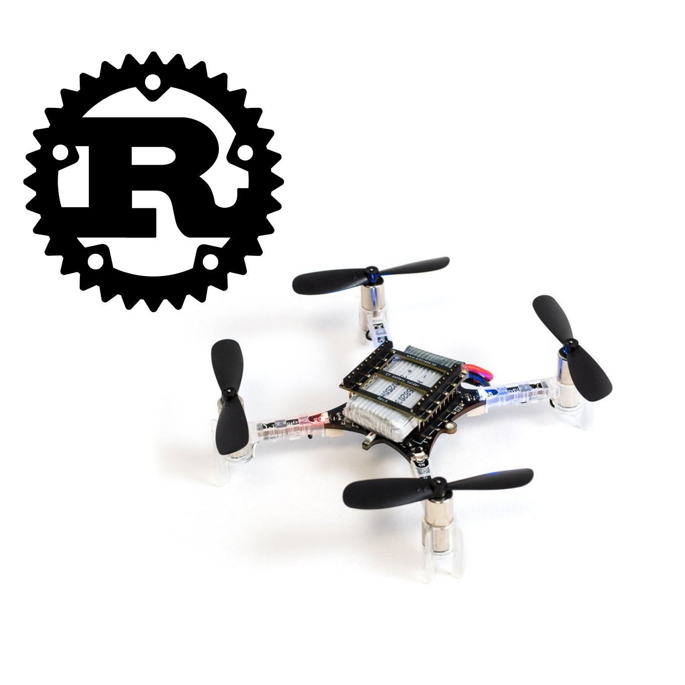
As a fan of functional languages like OCAML and Haskell (and Rust, which was strongly influenced by their approach), I wondered whether I couldn’t push this idea further, to get an even higher-level implementation of the algorithms. Having played a bit with Rust and encountered issues getting it to work efficiently with C++ (something that is thankfully now being addressed), I thought it might be work trying NASA Copilot, a Haskell extension that compiles Haskell into C with a fixed memory footprint (i.e., no malloc() or garbage-collection).
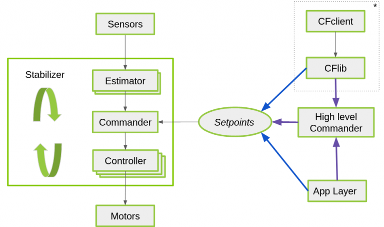
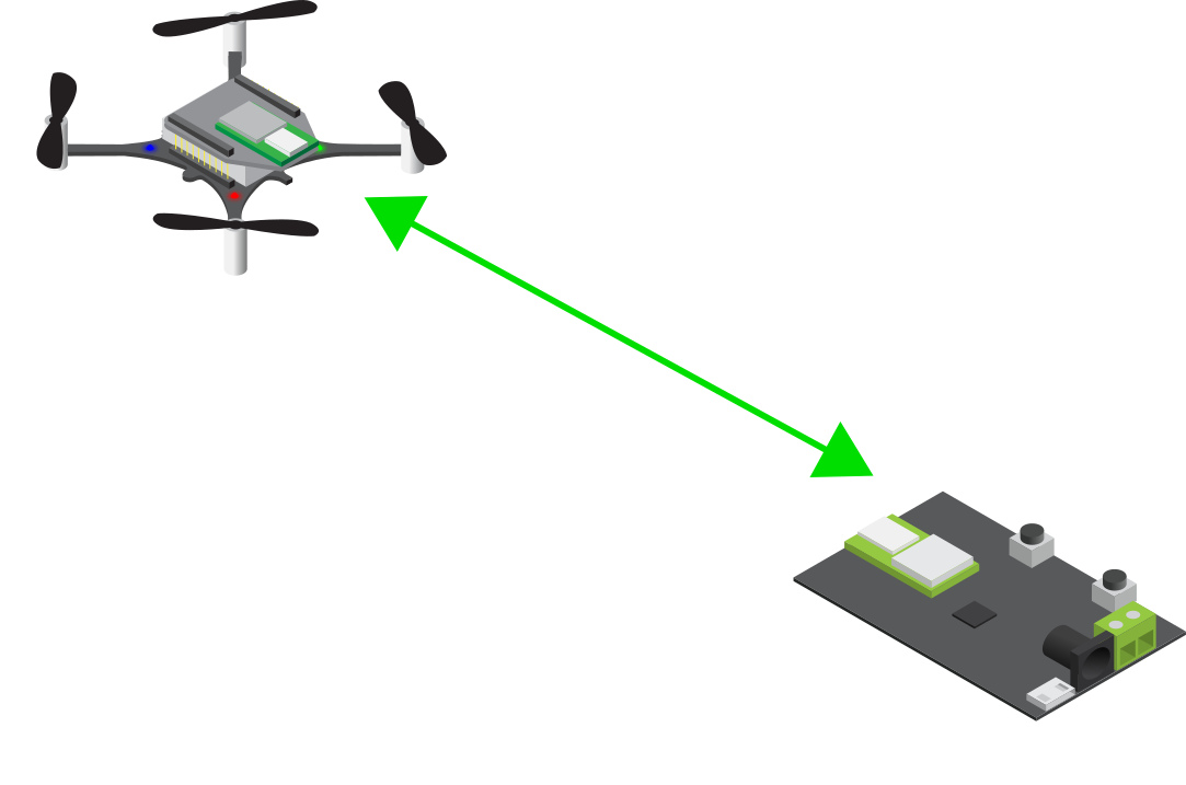
My efforts paid off, resulting in a Haskell library of algorithms for closed-loop (PID) control and motor mixing that works with both my modified version of the Crazyflie firmware and with a simulator like Webots. For anyone wondering “why Haskell”, I refer you to this excellent discussion on the language’s advantages (purity, elegance), as well as this classic presentation on why the functional programming offers a better solution to complex tasks than object-oriented approach. For example, the code in the LambdaFlight core module cleanly reflects the dataflow (input/output) diagram for a standard flight controller:
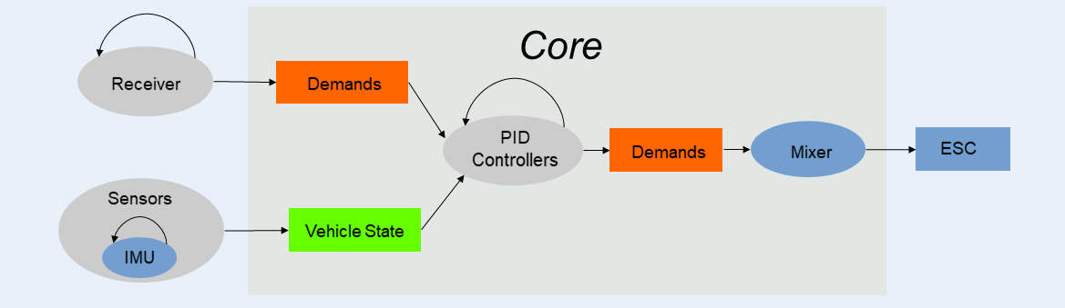
Here is the Haskell code corresponding the component labeled Core in the diagram:
— Clock rate is 500Hz for Crazyflie, 100Hz for sim
dt = rateToPeriod clock_rate
— Make a list of PID controllers based on application order
pids = [positionPid resetPids inHoverMode dt,
pitchRollAnglePid resetPids inHoverMode dt,
pitchRollRatePid resetPids inHoverMode dt,
altitudePid inHoverMode dt,
climbRatePid inHoverMode dt,
yawAnglePid dt,
yawRatePid dt]
— Run PID controllers on open-loop (stick) demands to get demands for motor mixer
demands’ = foldl (\demand pid -> pid vehicleState demand) openLoopDemands pids
— Adjust thrust component for hover mode
thrust” = if inHoverMode then ((thrust demands’) * tscale + tbase) else tmin
— Run motor mixer on closed-loop demands to get motor spins, scaled for CF or sim
motors = quadCFMixer $ Demands thrust”
((roll demands’) * prscale)
((pitch demands’) * prscale)
((yaw demands’) * yscale)
By adjusting the values of the clock rate and scaling coefficients (tscale, tbase, prscale, …), the same PID controllers (with same Kp, Ki, Kd constants) can be used for both the simulation and the actual Crazyflie.
Two pieces complete the picture.
First, how can a pure functional language like Haskell, lacking mutation/side-effects, support an algorithm like PID control, which requires keeping state variables (error integral, previous error) across iterations? The answer to this question comes from an ingenious part of the NASA Copilot framework, namely, streams. A stream (which is similar to a lazy list in Haskell), can come from an module of the program written in C (for example, the vehicle state obtained by state estimation) or from a previous value passed into the function. This feature allows Copilot to have functions that possess state while still being “pure” in the sense of being amenable to formal verification (mathematical proof of correctness; see this thread for a discussion). Although I don’t have the mathematical background to do formal verification proofs, the ability to prove the code correct is an extremely powerful feature of languages like Haskell and is what led NASA to develop the Copilot framework for its space missions.
Second, how can Haskell be combined with C/C++ without running into the performance issues typically encountered in calling code in one language from code in another? As I alluded to before, NASA Copilot solves this issue nicely, by compiling the Haskell code to C code with a fixed memory footprint. Declaring certain C/C++ variables to be global makes them accessible to the Haskell code as streams, and causes them to be compiled into the resulting C code, which can then be compiled and linked to the Crazyflie (or simulator) C/C++ code in the usual way (thanks to the Crazyflie Makefile’s use of the Kbuild system). Hence, to compile the whole project into a form suitable for flashing with make cload, requires just the following chain of commands (where make links creates links to some external libraries I wrote for the sensors):
make cf2_defconfig && make links && make copilot && make -j 32
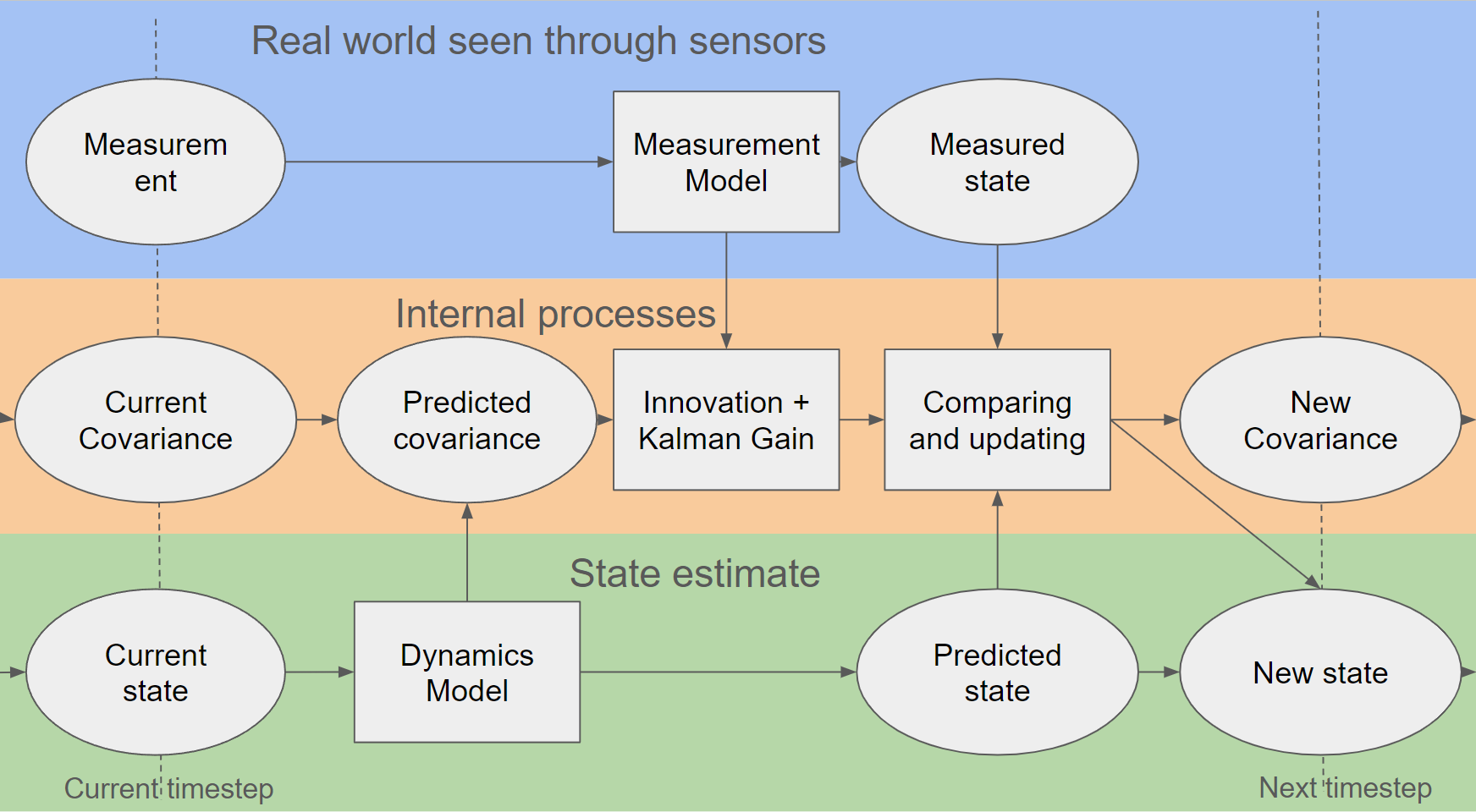
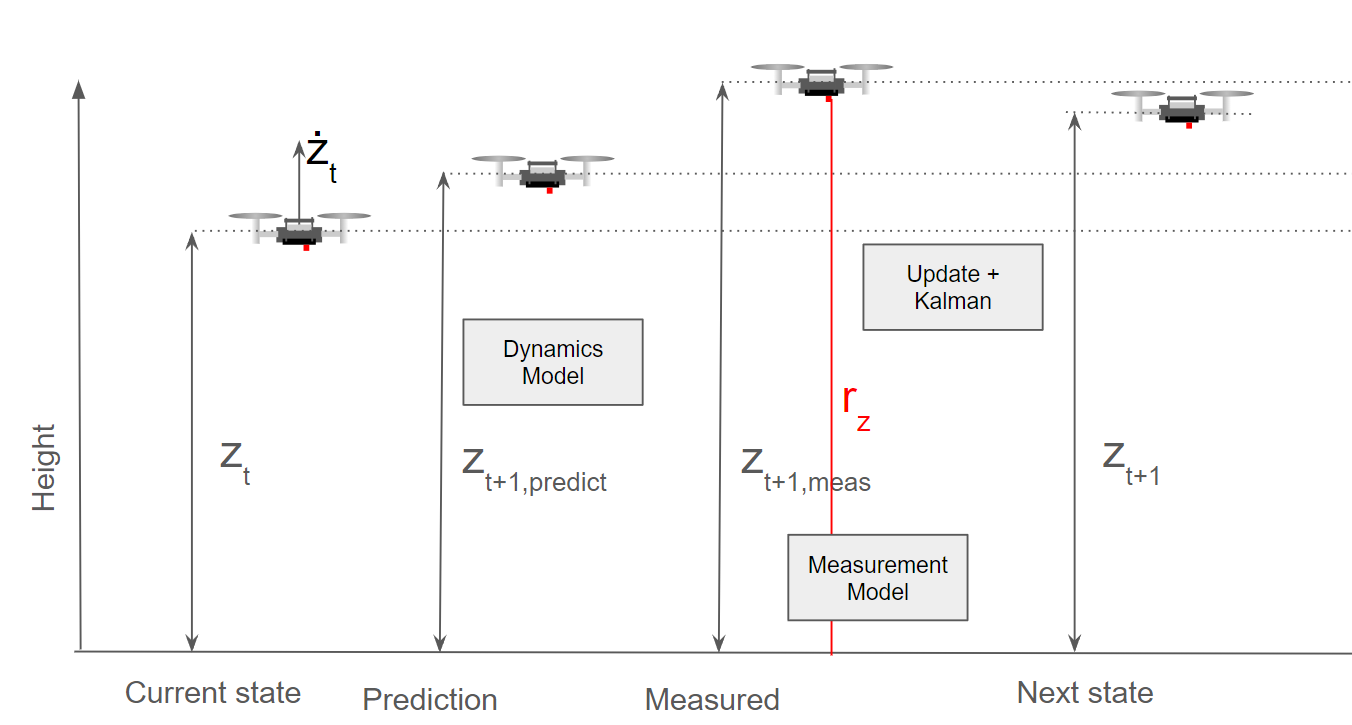
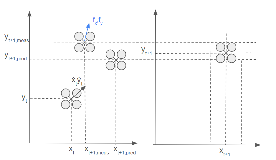
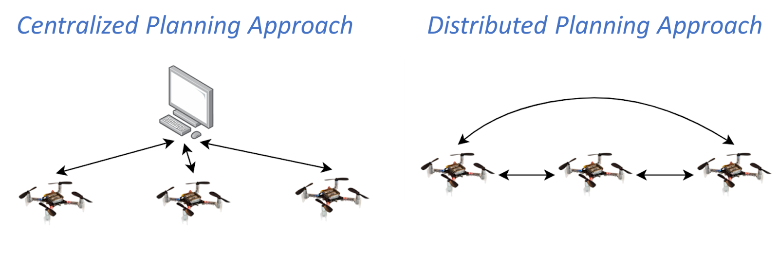
My current work focuses on two directions: first, I am translating Crazyflie’s Kalman filter into Haskell — a more ambitious undertaking, but one that I feel more confident in undertaking now that the core control algorithms are completed. Second, I am looking for ways of modifying the most popular robotics simulators (Webots, Gazbeo) to work with dynamics (physics engine) code custom-written for quadcopters and other aerial vehicles (like the dynamics code I wrote for this simulator), as well as faster control loops.
Announcements
There are some announcements that are not part of this guest blogpost that we’d like to share.
- The 350 mAh batteries are out of stock and unfortunately have a very long lead time at our manufacturer, so you can expect them to be back in stock early May. Please take a look this blogpost which also compares this battery to the Tattu alternative, if you can’t wait and need to have a similar battery now.
- We have a Bitcraze developer meeting this Wednesday to talk about the supervisor safety functionalities in the crazyflie-firmware. Please keep an eye on the GH discussion thread for information on how to join.