Today, Lennart Bult from Emergent Swarns presents us with this project of a 24/7 swarming demo. Enjoy!
Over the last few months our team has been working on creating a 24/7 swarming demo. Initially tasked by Guido de Croon and Chris Verhoeven from TU Delft MAVLab and the TU Delft Robotics Institute, we set out to find our way within the Crazyflie ecosystem to gradually increase the size and capabilities of the swarm. In this article we will first talk about some of the work and methods that we used. After that, we will introduce the TU Delft Science Centre Swarming Lab and talk about some applications of swarming drones.
Developing the 24/7 swarm
The project started in February with the goal of creating a physical swarm capable of real-time collision avoidance with drones and static obstacles. We started out with three drones equipped with the Flow Deck, and by setting them up in a clever way we could perform the first collision avoidance and landing tests. We were impressed with the performance we got out of the Flow Deck, however, eventually, it is mostly a battle against the drift of the position estimate, that is, we could increase some of the margins on the collision avoidance only so far before we would either fly out of the test zone or collide with another drone. Luckily with short test flights, we were able to see some of the flaws in our algorithms and correct them before testing with the new setup.
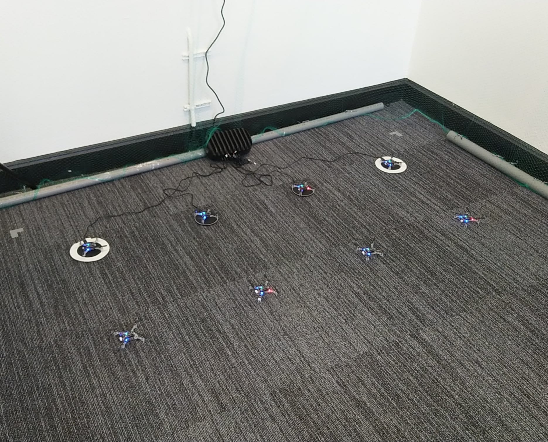
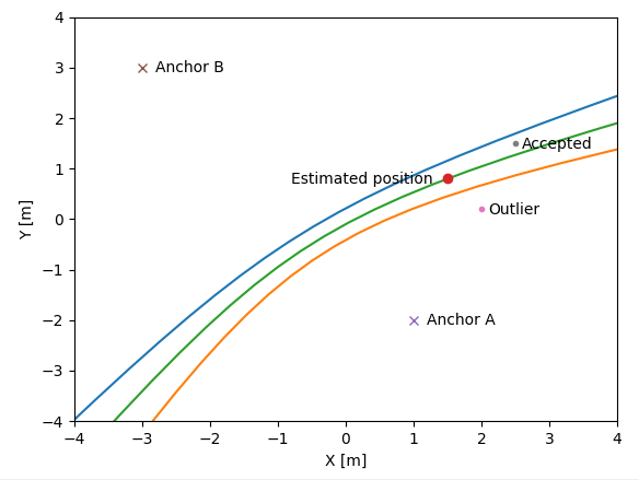
After a few weeks of testing we got approved for the first swarm expansion, five more drones and a Lighthouse positioning setup. This is when we could do our first real tests with the collision avoidance algorithm, which, much to our own surprise, worked on the first try. This is also when we first posted a project update on LinkedIn. There were however a lot of bugs that still needed to be worked out, and a lot of system experience still to be gained. After flying for a bit longer we noticed that some of the drones would flip quite often, which is when we discovered that we needed the thrust upgrade to control the additional weight of the larger battery and charging deck.
For the charging setup we took inspiration from the Bitcraze IROS 2022 demo; we 3D printed sloped landing pads that we tape onto a wireless charger. After a few iterations we landed on a design that uses minimal printer resources and allows the Crazyflie to land a bit off-center. This last feature turned out to be quite useful considering the large amount of destabilizing airflow that is generated by 40 drones. After receiving the last order of drones we also expanded the charging setup, which at this point takes up quite a bit of floor space. There are some ideas to create a vertical landing pad stack, which would bring the additional challenge of missing the landing pad not being an option.
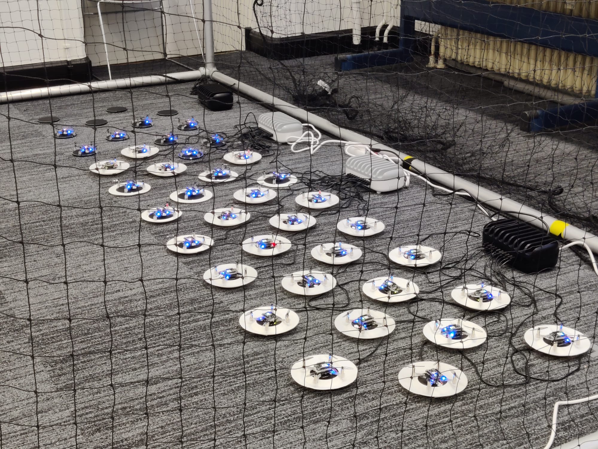
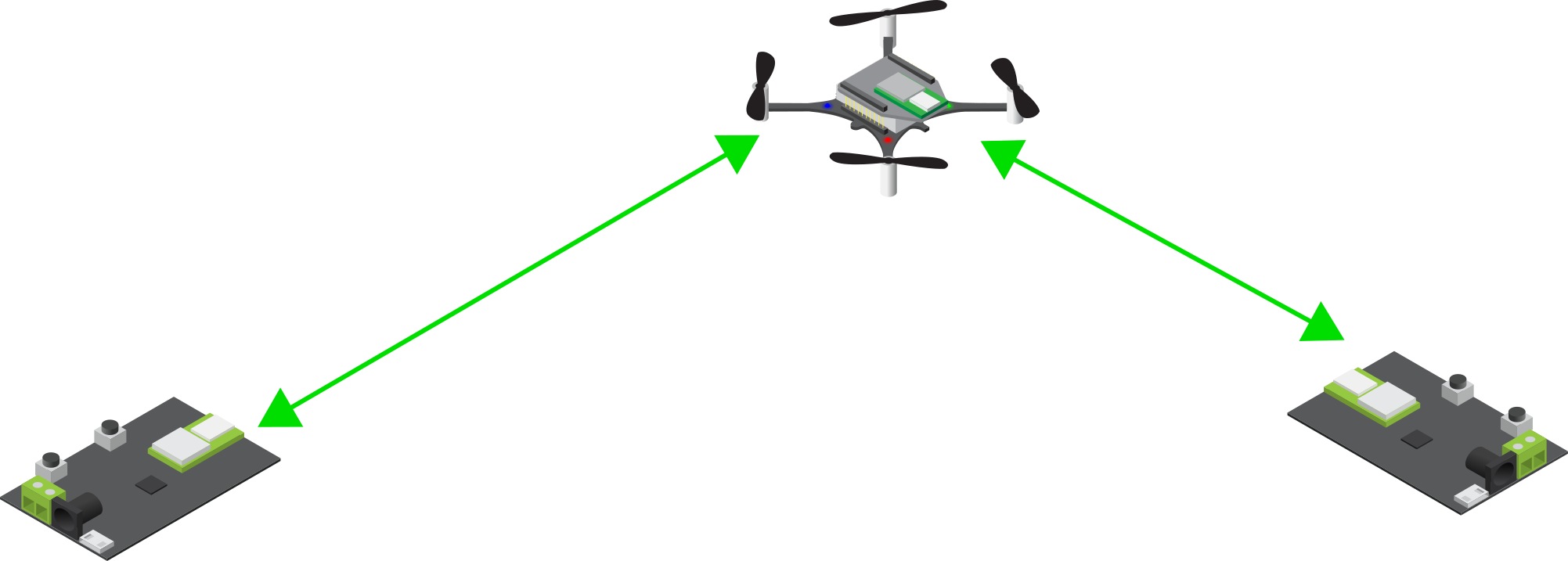
After prototyping the charging setup and building confidence with the initial setup, we were confident enough in our system capabilities to expand it to the point where a continuous demo of 5-8 drones is possible. Although the system integration of the previous expansion went without much trouble, we did encounter a few issues when expanding to 40 drones. The first issue of which was radio communication, we noticed that a delay in the radio communication would be present if we increased the update rate above a certain level for a specific number of drones per radio. The second issue we encountered were performance drops related to the violation of certain bounds in the collision avoidance algorithm. These two issues were very difficult to debug since it was not immediately obvious where the source of the issue was.
The third and last major issue was the increase in destabilizing airflow of 40 drones compared to 8. With 40 drones there is a noticeable breeze when you stand next to the drone cage, which is nice for summertime, but not so nice when drones need to land in a tight-packed configuration. To combat this issue there is a limit to the amount of drones that can land at the same time. There is also a minimum separation distance between two active landing pads, which reduced the severity of the induced turbulence. There are still ongoing efforts to increase the landing success rate, which is currently affected by drones running out of power during the landing procedure.
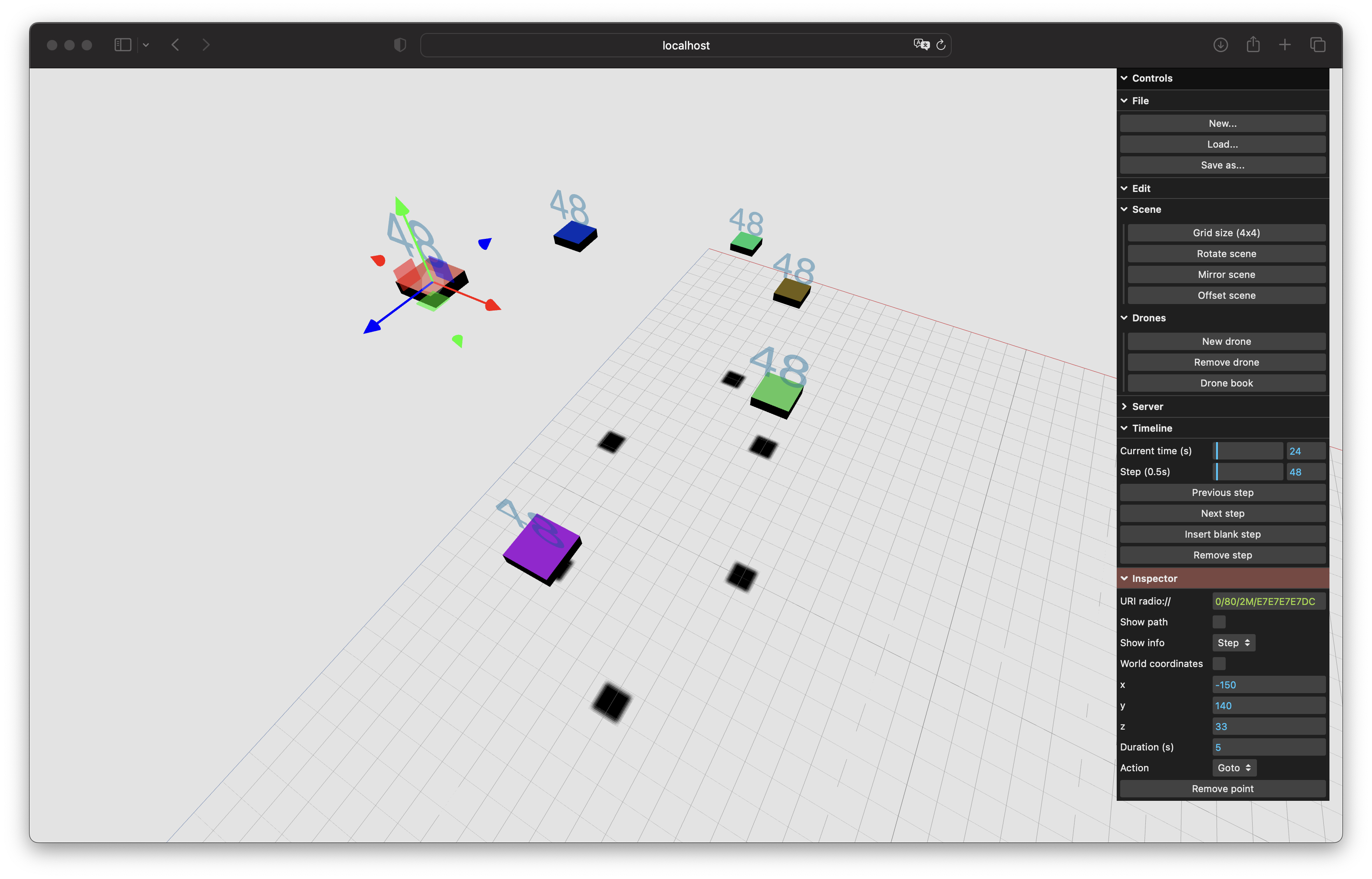
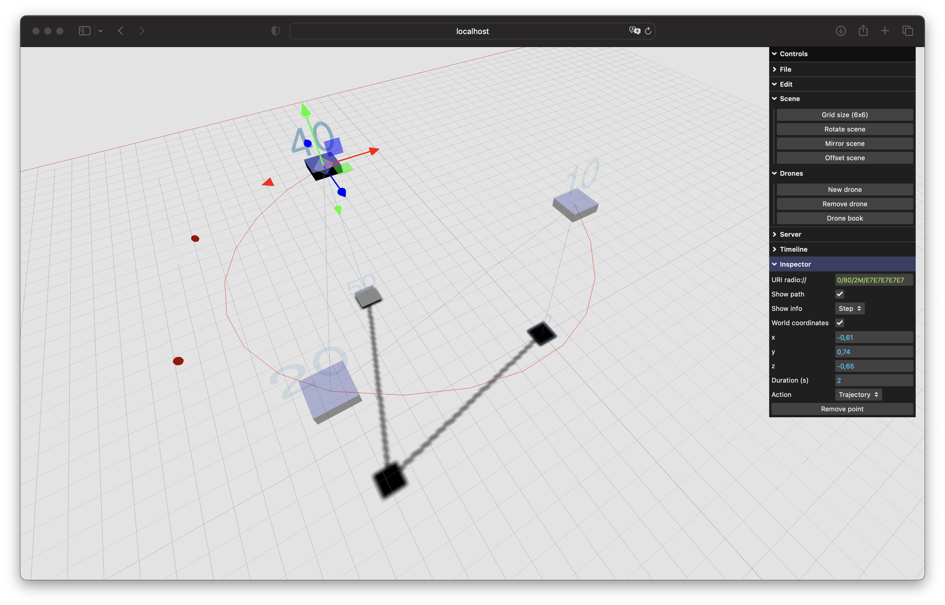
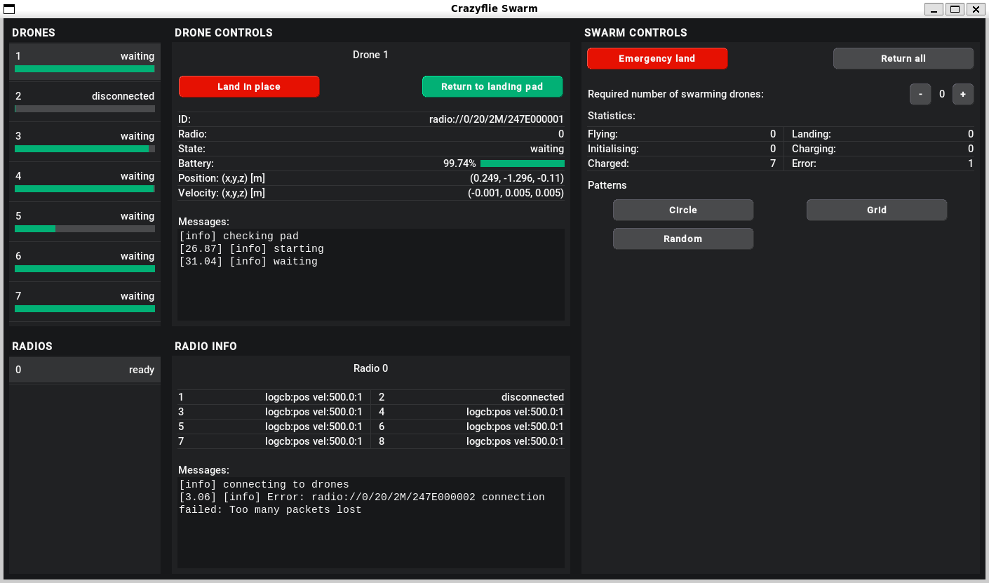
To control and monitor the swarm we designed a custom GUI, an impression of which you can see below. Although some of the buttons are still a work in progress, there are a lot of features that have already proven very useful, especially when testing a new feature.
The code base that we created for the swarm will be largely open-sourced (only the collision avoidance will not be open-source) to provide researchers all around the world with the possibility to setup their own Crazyflie swarm for research. You can find the repository through this link. Note that the documentation and code base are still under development and might contain bugs/errors.
Human interaction
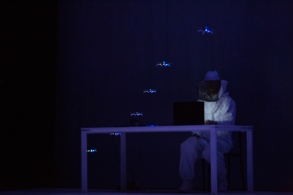
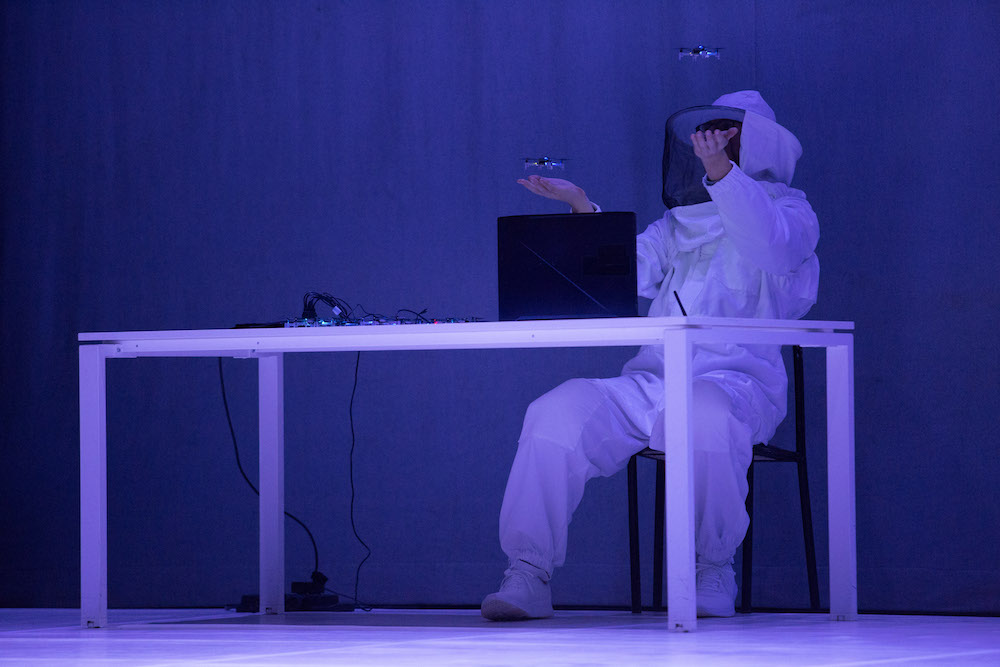
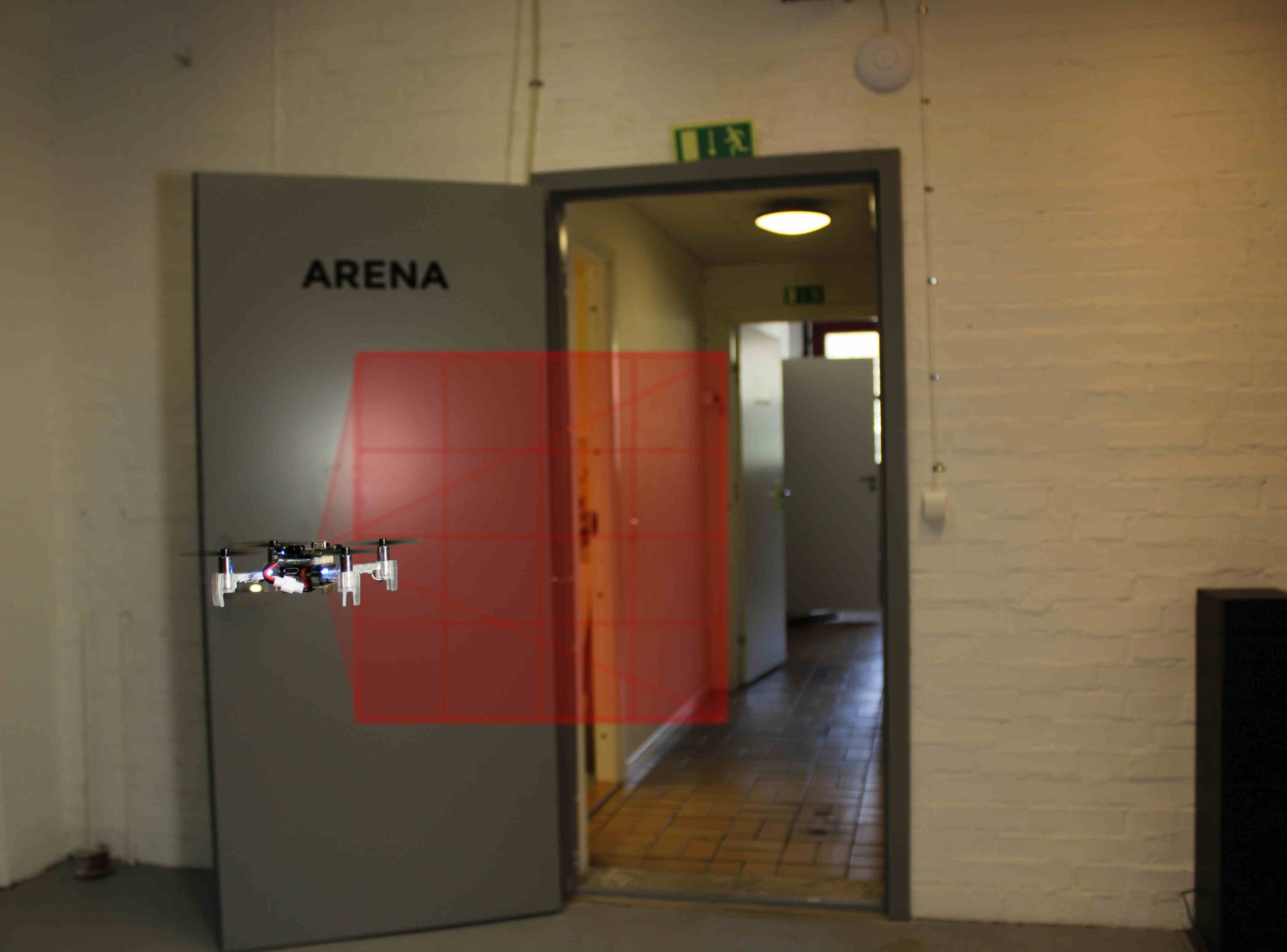
After creating all functionality to provide a continuously operating swarm demo, it was time to work on some of our stretch goals: 1. walking through the swarm whilst it is operating and 2. controlling the swarm using our arms. In the image below you can see an impression of precisely this functionality. The drones are following the operator’s gesture commands whilst performing live collision avoidance with an operator.
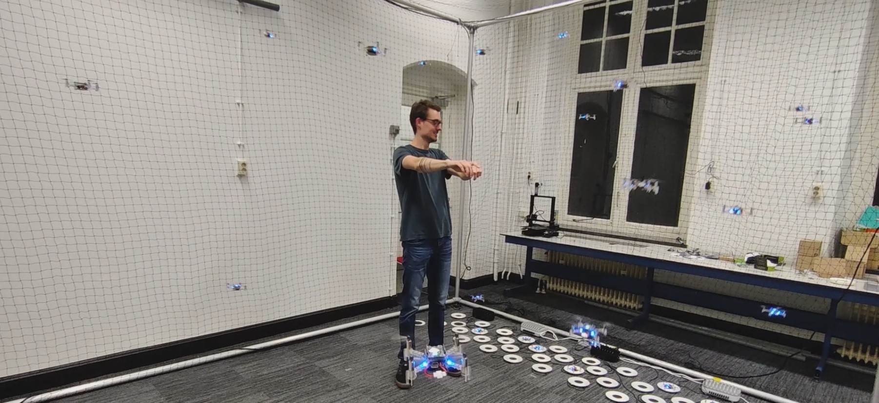
This demo requires multiple techniques and hardware elements working together to create a relatively low-latency, human-controlled swarm. We used a Kinect-like 3D sensor to perform human pose estimation, we subsequently used this data to create a dynamic obstacle in our collision avoidance software. An important element to consider here is the synchronization of the Lighthouse- and 3D sensor coordinate frames, i.e. without proper calibration the human will not be correctly positioned with respect to the drones and the drones will crash into the human. The interaction between the swarm control software and the human gesture commands also requires careful consideration, proper tuning is required to ensure a responsive system that is reliable and not too aggressive.
TUD Science Centre Swarming Lab
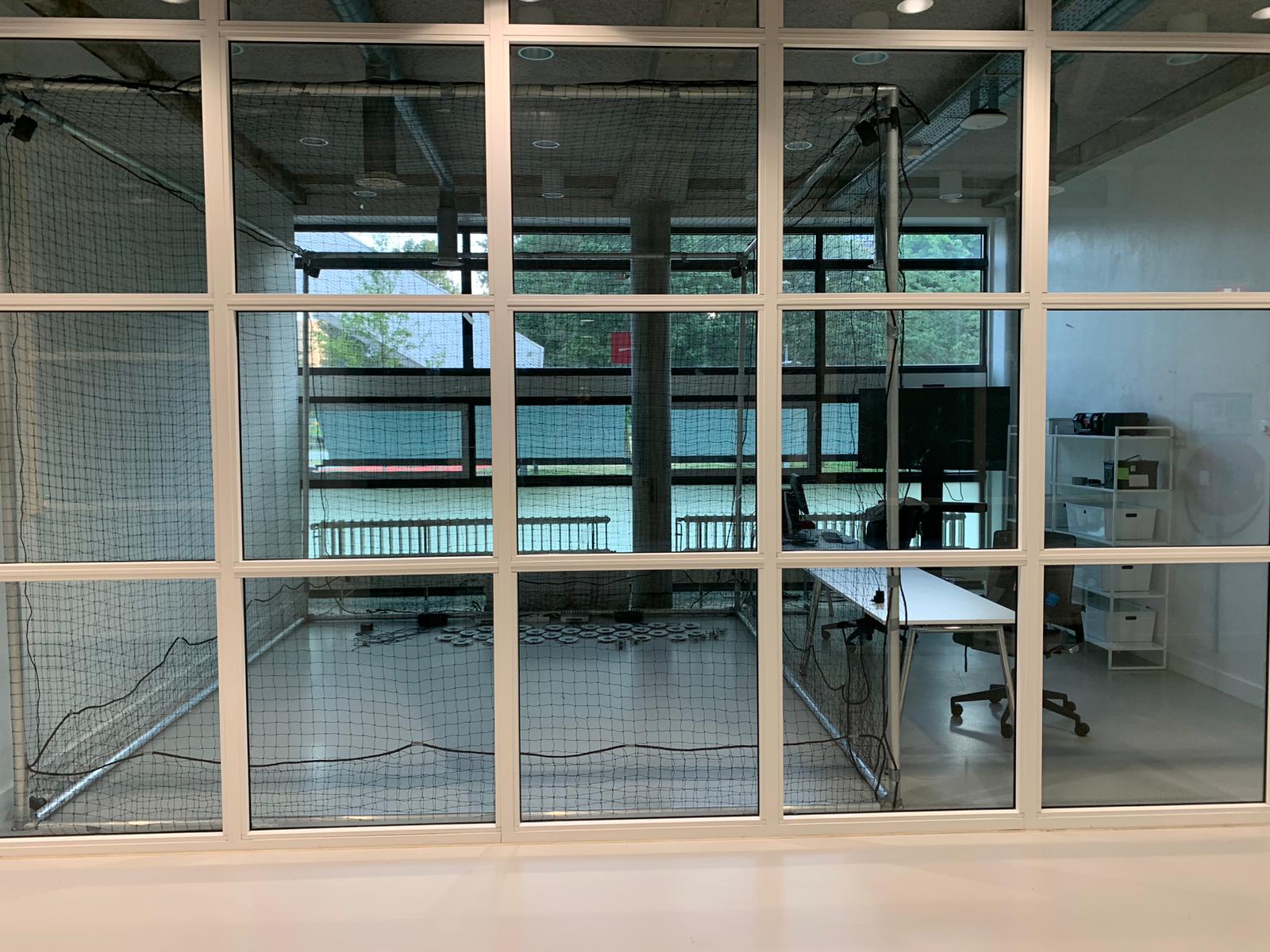
The next step in this project will be to set up the swarm at its new location, the TU Delft Science Centre. Here, the swarm will first and foremost be visible as a public demo, showcasing the capabilities of TU Delft state-of-the-art swarming research. There will also be a focus on developing the swarm as a research platform. This will allow TU Delft students and researchers to extend swarm functionalities and test their theory on a physical swarming system. Besides demos and academic research, there will also be worked on developing educational applications across the full educational board (primary school, high school and applied education). If you are interested in working on, or collaborating with the swarming lab on any of the above-mentioned tasks, feel free to email the lab management at operations.swarminglab@tudelft.nl.
Applications of Swarming
There are a lot of potential use-cases for fully autonomous drone swarms, ranging from indoor applications such as warehouse monitoring and factory inspection to outdoor applications such as search and rescue and surveillance. In our opinion, the true potential of drone swarms lies in applications where there is a significant need for a scalable system with a lot of built-in redundancy. A lot of additional use cases open up when we consider fully onboard autonomous systems, where the full benefits of decentralized swarming can be utilized. Currently, the size of drones needed to achieve such feats is quite large, though maybe in a few years, we could see more and more being done on drone platforms such as the Crazyflie.
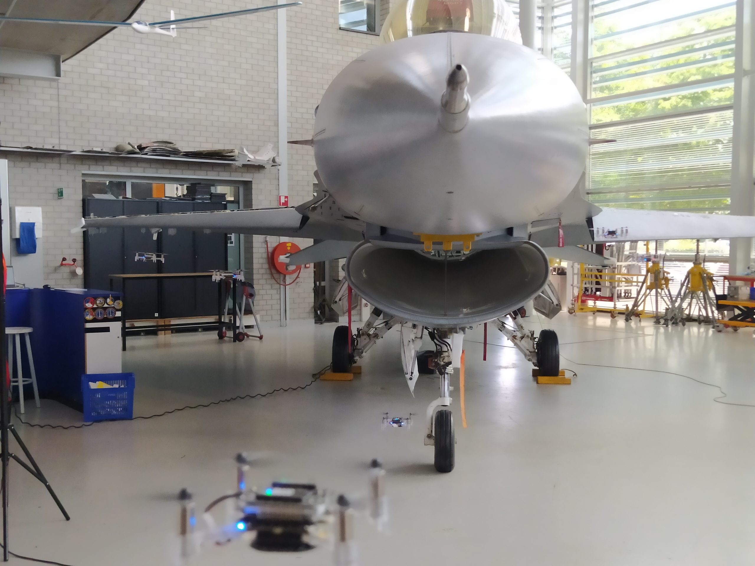
An interesting area of application for drone swarms could be in the inspection of aircraft. Drone swarms provide a scalable and flexible means to perform a fast inspection of aircraft across an entire airfield or military base. To showcase that this can be done with any size of drone, we went to Deltion College in Zwolle to perform a mock inspection of an F-16 fighter jet. Above you can see an impression of the inspection. Another area of application is search and rescue, where there is a need for systems that can find people or objects of interest in unknown and cluttered environments. Furthermore, the area that needs to be searched is usually very large and sometimes difficult to travel on foot. A drone swarm could provide fast and reliable coverage of the area of interest, whilst providing full data traceability. Seppe and Lennart will work on creating drone swarms for these use cases with the start-up Emergent Swarms.