As you might expect, we use the Crazyflie python client a lot at Bitcraze. The client has a lot of features, ranging from setting up LPS/Lighthouse systems to turning on/off the headlight LEDs on the LED-ring deck. But some of the features we use the most is probably the console view as well as the logging/parameter subsystems. A lot of the time we modify firmware, flash it and want to tweak (via parameters) or to check if the changes are working as expected (via the console or logging). Then switching from the terminal, where we build/flash, to the Qt UI in the Crazyflie python client can be a hassle if you just want to do something quick. It would be great to be able to log/set variables directly from the terminal, well now you can!
Meet the Crazyflie command-line client, a fun Friday project I worked on a while back. The CLI is written in Rust and was made possible thanks to a previous fun Friday project by Arnaud on the Rust Crazyflie link/lib, which has now moved to the official Bitcraze repositories. The CLI project is still very limited, but has some basic functionality:
Scan for Crazyflies and pre-select one to interact with
List loggable variables, create log configurations and print their value
List parameters and get/set them
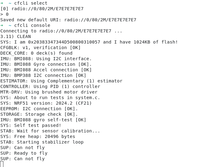
Show the Crazyflie console
Last week the first version, v0.1.0, was released on crates.io. So if you have Rust set up on your computer and want to test it out then all you need to do is to type “cargo install cfcli“. The CLI still only has some basic functionality, but hopefully it can be expanded in the future with more useful things! Feel free to leave any issues or comments you might have on the Github page.
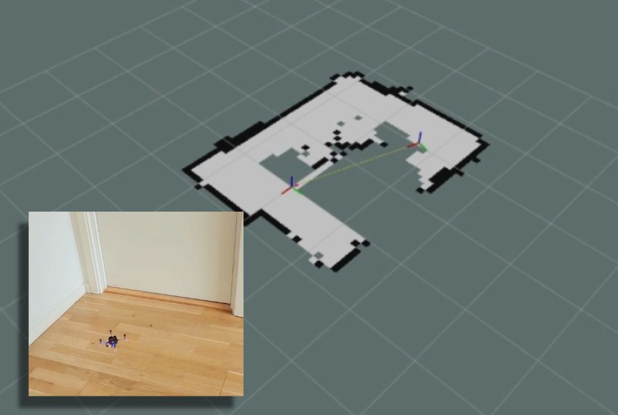
You might remember that at the beginning of this summer, we were invited to do a skill-learning session with the Crazyflie at the Robotics Developer Day 2024 (see this blog post) organized by The Construct. We showed the Crazyflie flying with the multi-ranger deck, capable of mapping the room in both simulation and the real world. Moreover, we demonstrated this with both manual control and autonomous wall-following. Since then, we wanted to make some improvements to the simulation. We now present an updated tutorial on how to do all of this yourself on your own machine.
Note: This tutorial was originally developed for a demonstration at Robotics Developer Day 2024. As the integration depends on specific versions of ROS 2, Gazebo, and related packages, it may require adjustments to work with current software. This post is no longer actively maintained by the Bitcraze team.
This tutorial will focus on using the multi-ranger ROS 2 nodes for both mapping and wall-following in simulation first, before trying it out on the real thing. You will be able to tune settings to your specific environment in simulation first and then use exactly the same nodes in the real world. That is one of the main strengths of ROS, providing you with that flexibility.
We have made a video of what to expect of the tutorial, for which you should use this blogpost for the more detailed instructions.
Watch this video first and then again with the instructions below
What do you need first?
You’ll need to setup some things first on the PC and acquire hardware to follow this tutorial in full:
Gazebo Harmonic – Install via these instructions This is not the recommended Gazebo for humble but we will install the specific ROS bridge for this later. Just make sure that you don’t have gazebo classic installed on your machine.
Hardware
You’ll need to components at least of the STEM ranging bundle
If you have any different setup of your computer or positioning system, it is okay as the demos should be simple enough to work, but, be prepared for some warning/error handling that this tutorial might have not covered.
Time to complete:
This is an approximation of how much time you need to complete this tutorial, depended on your skill level, but if you already have experience with both ROS 2/Gazebo and the Crazyflie it should take 1 hour.
If you have the Crazyflie for the first time, it would probably be a good idea to go through the getting started tutorial and connect to it with a CFclient with the Flowdeck and Multi-ranger deck attached as a sanity check if everything is working before jumping into ROS 2 and Gazebo.
Go to the ros2_ws workspace and build the packages
cd ~/crazyflie_mapping_demo/ros2_ws/
source /opt/ros/humble/setup.bash
colcon build --cmake-args -DBUILD_TESTING=ONCode language:JavaScript(javascript)
Building will take a few minutes. Especially Crazyswarm2 will show a lot of warnings and std_err, but unless the package build has ‘failed’, just ignore it for now until we have proposed a fix to that repository.
If the build of all the packages passes and non failed, please continue to the next step!
2. Simple mapping simulation
This section will explain how to create a simple 2D map of your environment using the multi-ranger. The ROS 2 package designed for this is specifically made for the multi-ranger, but it should be compatible with NAV2 if you’d like. However, for now, we’ll focus on a simple version without any localization inferred from the map.
Open up a terminal which needs to be sourced for both the gazebo model and the newly build ROS 2 packages:
If you get a ‘No such file or directory’ error on the model, try entering the full path in GZ_SIM_RESOURCE_PATH export.
Gazebo will start with the Crazyflie in the center. You can get a close-up of the Crazyflie by right-clicking it in the Entity tree and pressing ‘Move to’. You can also choose to follow it, but the camera tracking feature of Gazebo needs some tuning to track something as small as the Crazyflie. Additionally, you will see RVIZ starting with the map view and transforms preconfigured.
Open up another terminal, source the installed ROS 2 distro and open up the ROS 2 teleop keyboard node:
source /opt/ros/humble/setup.bash
ros2 run teleop_twist_keyboard teleop_twist_keyboard
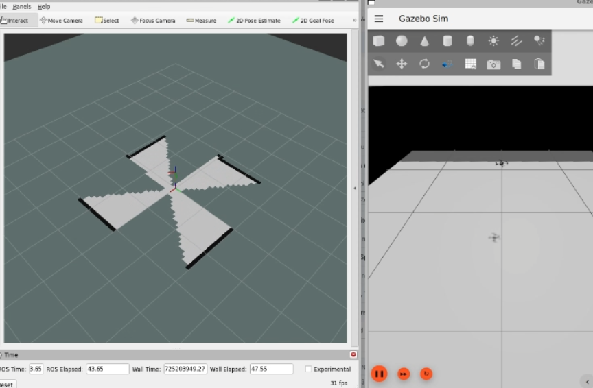
Have the Crazyflie take off with ‘t’ on your keyboard, and rotate it around with the teleop instructions. In RVIZ you should see the map being created and the transform of the Crazyflie moving. You should be able to see this picture, and in this part of the video.
Screenshot of the Crazyflie in Gazebo generating a map with Teleop (video)
3. Simple mapping real world
Now that you got the gist of it, let’s move to the real Crazyflie!
First, if you have a different URI of the Crazyflie to connect to, first change the config file ‘crazyflie_real_crazyswarm2.yaml’ in the crazyflie_ros2_repository. This is a file that Crazyswarm2 uses to know to which Crazyflie to connect to.
Open up the config file in gedit or your favorite IDE like visual code:
and change the URI on this line specifically to the URI of your Crazyflie if necessary. Mind that you need to rebuild ros2_ws again to make sure that this has an effect.
Now source the terminal with the installed ROS 2 packages and the Gazebo model, and launch the ROS launch of the simple mapper example for the real world Crazyflie.
Now open up another terminal, source ROS 2 and open up teleop:
source /opt/ros/humble/setup.bash
ros2 run teleop_twist_keyboard teleop_twist_keyboard
Same thing, have the Crazyflie take off with ‘t’, and control it with the instructions.
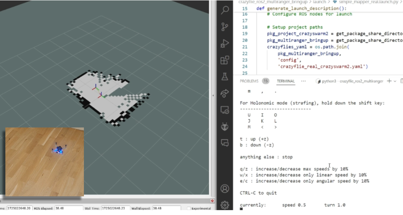
You should be able to see this on your screen, which you can also check with this part of the video.
Screen shot of the real Crazyflie mapping while being controlled with ROS 2 teleop (video)
Make the Crazyflie land again with ‘b’, and now you can close the ROS 2 node in the launch terminal with ctrl + c.
4. Wall following simulation
Previously, you needed to control the Crazyflie yourself to create the map, but what if you could let the Crazyflie do it on its own? The `crazyflie_ros2_multiranger` package includes a `crazyflie_ros2_multiranger_wall_following` node that uses laser ranges from the multi-ranger to perform autonomous wall-following. Then, you can just sit back and relax while the map is created for you!
Let’s first try it in simulation, so open up a terminal and source it if you haven’t already (see section of the Simple mapper simulation). Then launch the wall follower ROS 2 launch file:
Take off and wall following will go fully automatic. The simulated Crazyflie in Gazebo will fly forward, stop when it sees a wall with it’s forward range sensor and follow the wall on its left-hand side.
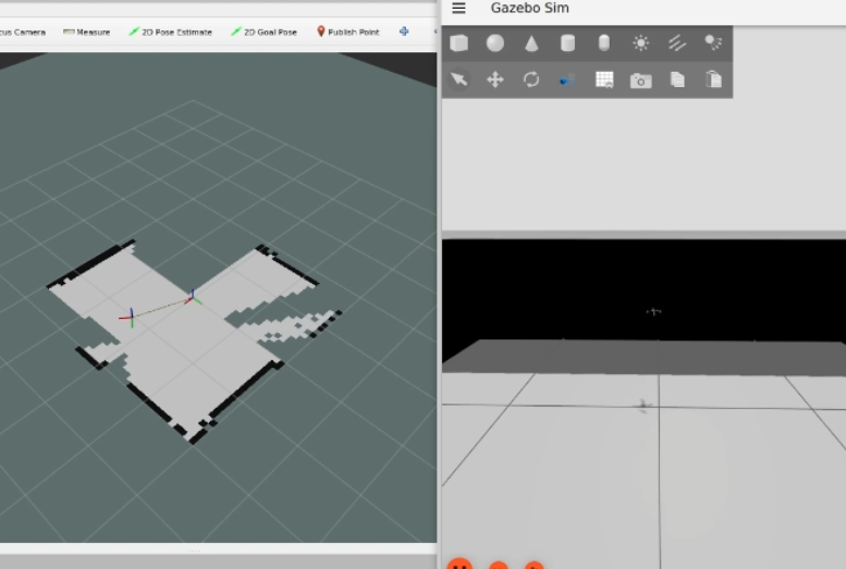
You’ll see on RVIZ2 when the full map is created like here below and this part of the tutorial video.
Screenshot of the simulated Crazyflie in Gazebo mapping will autonomously wall following (video)
You can stop the simulated Crazyflie by the following service call in another terminal that is sourced with ROS 2 humble.
ros2 service call /crazyflie/stop_wall_following std_srvs/srv/Trigger
The simulated Crazyflie will stop wall following and land. You can also just close the simulation, since nothing can happen here.
5. Wall following real world
Now that we have demonstrated that the wall-following works in simulation, we feel confident enough to try it in the real world this time! Make sure you have a fully charged battery, place the Crazyflie on the floor facing the direction you’d like the positive x-axis to be (which is also where it will fly first), and turn it on.
Make sure that you are flying with a room with clear defined walls and corners, or make something with cardboard such as a mini maze, but the current algorithm is optimized to just fly in a squarish room.
Source the ROS 2 workspace like previously and start up the wall follower launch file for the
Like the simulated Crazyflie, the real Crazyflie will take off automatically and automatically do wall following, so it is important that it is flying towards a wall. It should look like this screenshot, or you can check it with this part of the video.
The real crazyflie wall following autonomously while mapping the room (video).
Be careful here to not accidently run this script with the Crazyflie sitting on your desk!
If you’d like the Crazyflie to stop, don’t stop theROS2 nodes with ctrl-c, since it will continue flying until crash. It’s not like simulation unfortunately where you can close the environment and nothing will happen. Instead, use the ROS 2 service made for this in a different terminal:
ros2 service call /crazyflie_real/stop_wall_following std_srvs/srv/Trigger
Similar the real Crazyflie will stop wall following and land. Now you can close the ROS 2 terminals and turn off the crazyflie.
Next steps?
We don’t have any more demos to show but we can give you a list of suggestions of what you could try next! You could for instance have multiple Crazyflies mapping together like in the video shown here:
This uses the mapMergeForMultiRobotMapping-ROS2 external project, which is combined with Crazyswarm2 with this launch file gist. Just keep in mind that, currently, it would be better to use a global positioning system here, such as the Lighthouse positioning system used in the video. Also, if you’d like to try this out in simulation, you’ll need to ensure different namespaces for the Crazyflies, which the current simulation setup may not fully support.
Another idea is to connect the NAV2 stack instead of the simple mapper. There exists a couple of instructions on the Crazyswarm2 ROS2 tutorials so you can use those as reference. Check out the video below here.
Moreover, if you are having difficulties setting up your computer, I’d like to remind you that the skill-learning session we conducted for Robotics Developer Day was entirely done using a ROSject provided by The Construct, which also allows direct connection with the Crazyflie. The only requirement is that you can run Crazyswarm2 on your local machine, but that should be feasible. See the video of the original Robotics Developer Day skill-learning session here:
The last thing to know is that the ROS 2 nodes in this tutorial are running ‘offboard,’ so not on the Crazyflies themselves. However, do check out the Micro-ROS examples for the Crazyflie by Eprosima whenever you have the time and would like to challenge yourself with embedded development.
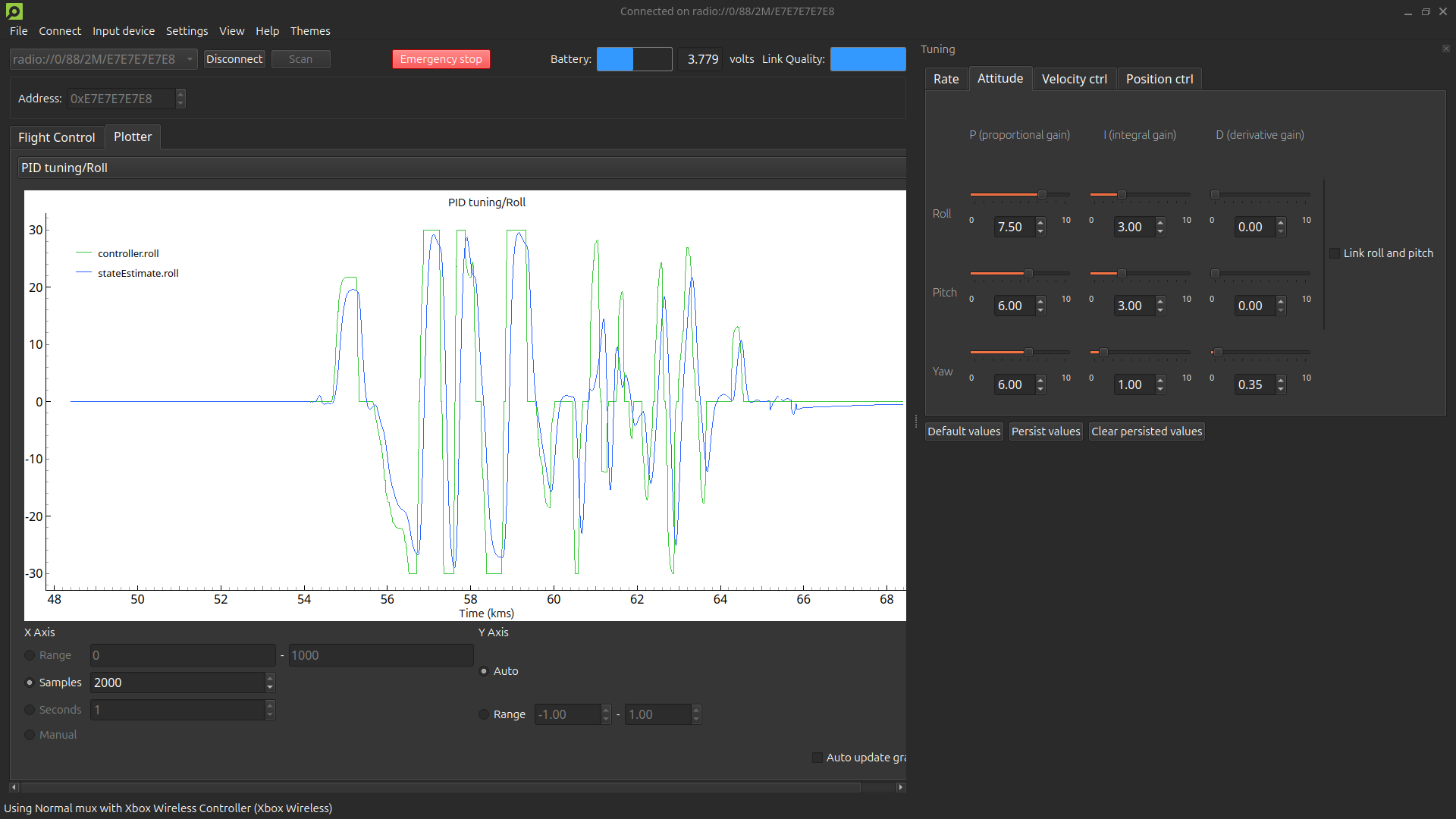
We are excited to announce the release of our new PID Tuning Guide! This guide is designed to help users understand and apply the basics of PID tuning within our ecosystem, making it easier to achieve stable and responsive flight for your Crazyflie. This guide is particularly useful if you’ve modified your drone, such as adding expansion decks or changing its motor and/or propeller configuration. While our default tuning is designed to work in a wide range of situations and configurations, fine-tuning your PID settings can enhance performance for your specific setup and flight profile.
Interface with tuning toolbox and plotter displaying the roll angle setpoint and the roll angle state estimate.
What’s in the guide?
The guide covers essential topics, including:
Fundamental PID Concepts: Understand the role of Proportional, Integral, and Derivative parameters in controlling your Crazyflie’s movements.
Step-by-Step Instructions: Learn how to set up your software, and use cfclient for tuning.
Practical Tuning Tips: Get insights on adjusting PID gains, using the tuning toolbox, and conducting safe manual flight tests.
Why this guide is useful
Even though this guide focuses on the basics, it provides a solid foundation for anyone new to PID tuning. Whether you’re using the Crazyflie 2.1, Crazyflie 2.0, or a custom-built quadcopter with the Crazyflie Bolt, this guide will help you:
Understand how PID controllers work and why they are important.
Use the cfclient for PID tuning within our ecosystem.
Safety first
We prioritize safety in our guide. Always secure your quadcopter in a safe environment, use protective gear, and configure an emergency stop on your controller to ensure a safe tuning process.
Get started with PID tuning today!
Ready to improve your quadcopter’s flight performance? Check out our PID Tuning Guide and start tuning.
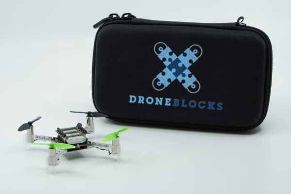
This week, we have a guest blog post from Scott at Droneblocks.
DroneBlocks is a cutting-edge platform that has transformed how educators worldwide enrich STEM programming in their classrooms. As pioneers in the EdTech space, DroneBlocks wrote the playbook on integrating drone technology into STEM curriculum for elementary, middle, and high schools, offering unparalleled resources for teaching everything from computer science to creative arts. What started as free block coding software and video tutorials has become a comprehensive suite of drone and robotics educational solutions. The Block-Coding software still remains free to all, as the DroneBlocks mission has always been to empower educators and students, allowing them to explore and lead the way. This open-source attitude set DroneBlocks on a mission to find the world’s best and most accessible micro-drone for education, and they found it in Sweden!
Previously, DroneBlocks had worked alongside drone juggernaut DJI and their Tello Drone. The Tello was a great tool for its time, but when DJI decided to discontinue it with little input from its partners and users, it made the break much easier. The hunt began for a DJI Tello replacement and an upgrade!
Bitcraze’s choice to build Crazyflie as an open platform had their drone buzzing wherever there was curiosity. The Crazyflie was developed to fly indoors, swarm, and be mechanically simplistic. DroneBlocks established that the ideal classroom micro-drone required similar characteristics. This micro-drone needed to be small for safety but sturdy for durability. It also needed to be easy to assemble and simple in structure for students new to drones. Most importantly, the ideal drone needed to have an open line of software communication to be fully programmable. Finally, there had to be an opportunity for a long-lasting partnership with the drone manufacturer, including government compliance.
After extensive searching and testing by DroneBlocks, the Crazyflie was a diamond in the rough – bite-sized and lightweight, supremely agile and accurate, reliable and robust, and most importantly, it was an open-source development platform. The DroneBlocks development team took the Crazyflie for a spin (or several) and with excitement, it was shared with the larger curriculum team to be mined for learning potential. It was promising to see Crazyflie’s involvement in university-level research studies, which proved it meant business. DroneBlocks knew the Crazyflie had a lot going for it – on its own. The team imagined how, when paired with DroneBlocks’ Block Coding software, Flight Simulator, and Curriculum Specialists, the Crazyflie could soar to atmospheric heights!
Hardware? Check. Software? Check. But what about compatibility? DroneBlocks was immediately drawn to the open communication and ease of conversation with the Bitcraze team. It was obvious that both Bitcraze and DroneBlocks were born from a common thread and shared a mutual goal: to empower people to explore, investigate, innovate, research, and educate.
DroneBlocks has since built a new Block Coding interface around the Crazyflie, allowing students to pilot their new drone autonomously and learn the basics of piloting and coding concepts. This interface is offered with a brand new drone coding simulator environment so students can test their code and fly the Crazyflie in a virtual classroom environment.
The Crazyflie curriculum currently consists of courses covering building, configuring, and finally, programming your drone with block coding (DroneBlocks) and Python. DroneBlocks’ expert curriculum team designed these courses to enable learners of all ages and levels to learn step by step through video series and exercises. New courses around block coding and Python are in constant development and will be continuously added to the DroneBlocks curriculum platform.
Crazyflie Drones now headline DroneBlocks’ premiere classroom launch kit. The DroneBlocks Autonomous Drones Level II kit encompasses everything a middle or high school would need to launch a STEM drone program, including the hardware, necessary accessories, and safety wear paired with the DroneBlocks software and curriculum. As a result, thousands of new students have entered the world of Drones and programming thanks to the Bitcraze + DroneBlocks partnership.
DroneBlocks has become an all-inclusive drone education partner for engaging and innovative learning experiences—and the Crazyflie delivers this by being a cutting-edge piece of hardware in a clever package.
Welcome to the “The Beginner’s Guide to Drones” for programmers curious about exploring the world of unmanned aerial vehicles (UAVs). If you’re a coder from another field, this guide will walk you through the basics of drones, their components, and how to start programming them. Let’s dive in and see how your coding skills can take flight!
If you come from an engineering field, you might already know the basics of some of these topics, however you might still have use of the overview and can use the resources to get more specific knowledge.
The Robotics part
First and foremost, you’ll need some basic robotics skills. We start of with the most basic question, “What is a Robot?”. A robot uses sensors to create an internal model of its environment, and actuators to act on/in its environment. The specifics of the internal model depend on the robot’s purpose, but a crucial component is understanding its location and orientation within that environment.
Linear algebra basics
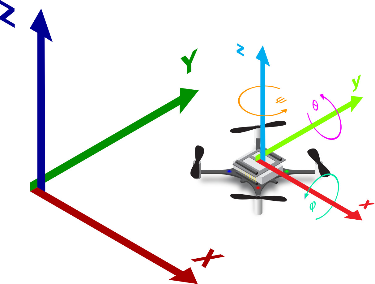
To understand how a quadcopter perceives its environment and its own position, you’ll need some basic skills in linear algebra, particularly in matrices, vectors, and frame rotation. These skills are essential for comprehending the mathematical principles behind quadcopter navigation.
To build an internal model of its own movement and orientation, an Inertial Measurement Unit (IMU) is used. An IMU consists of a gyroscope, an accelerometer, and sometimes a magnetometer. These sensors, when combined using sensor fusion techniques (See “Control Theroy” below), help determine the quadcopter’s angular velocity and linear acceleration. This data allows the drone to calculate its orientation and movement.
Picture of a Crazyflie in relation to a reference frame from Bitcraze.io
The quadcopter can now determine its relationship to its starting position and the gravitational field. However, relying solely on an IMU tends to cause drift over time. Imagine trying to stand on one leg with your eyes closed—eventually, you’ll lose balance.
For improved stability, a drone often needs additional sensors, such as a camera, to help stabilize its position. Other sensor systems can also be used to determine relative or absolute position. While an IMU can sense changes in position relative to a starting point, an external positioning system is necessary for stability and obtaining absolute positions. This system acts as a reference frame for the drone.
Drones flying outdoors typically use GPS combined with RTCM, since it is available almost anywhere, ease to use, and has centimeter-level accuracy.
For indoor use, as with Crazyflies, the default used positioning system is motion-capture system but there are others as well. This area is at the cutting edge of science, with new technologies emerging constantly. However, many effective systems are available, though they may have constraints regarding power efficiency, flight area size, update speed, or precision.
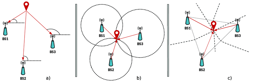
This is an image of some common techniques for positioning. a) AOA, b) TOA, TWR c) TDOA taken from Researchgate.com
Control theory
Now that drone can understand its position and orientation in space, the next step is figuring out how to move within this space. Moving from point A to point B involves setting a “setpoint” and then determining how to use the drone’s actuators to reach this setpoint most efficiently. This is where control theory comes into play.
Drones generally use some sort of feedback control system, which in its most basic form looks something like this:
A very basic overview of a system with feedback control
In this system, the error (the difference between the current position and the setpoint) is fed back into the system to ensure the drone moves in a way that minimizes the error over time.
Various algorithms can calculate the best actuator output based on the error and current state. One of the most fundamental algorithms is the PID controller, which works well for linear systems. Understanding PID controllers requires some basic calculus, but the concept is straightforward. Here are some resources for simple explanations:
For IMUs, there is a particularly useful filter to know about, given its widespread use. The accelerometer and gyroscope each have their own profiles of noise and drift. The accelerometer is sensitive to short-term noise, while the gyroscope drifts slowly over time. To mitigate these issues, a combination of both measurements is often used. The complementary filter is ideal for this situation, leveraging the strengths of both sensors to correct the measurements effectively.
For more complex scenarios, advanced controllers like Kalman filters and others can be used. It’s also possible to combine multiple controllers to achieve better performance.
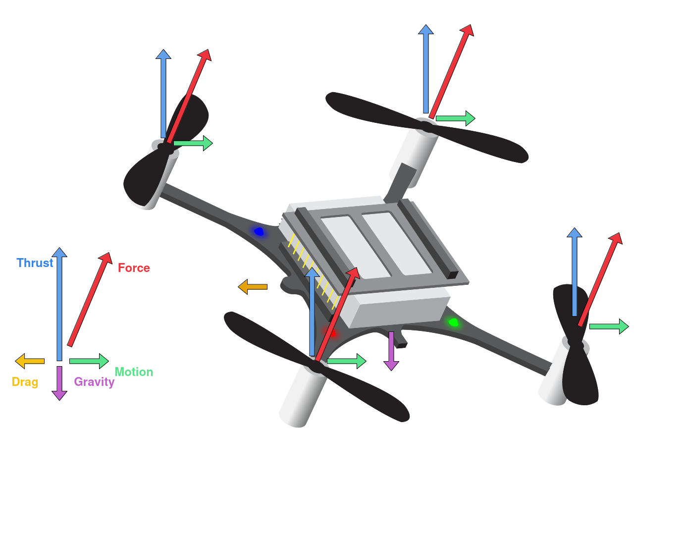
Drone actuators, primarily consisting of motors and propellers, are critical for controlling a drone’s movement and stability. The motors and propellers are typically called the “drive train” or “power train”. The motors used on drones are usually brushed or brushless DC motors. Propellers are attached to the motors and generate lift by pushing air downwards. The size, shape, and pitch of the propellers affect the drone’s performance, including speed, lift, and maneuverability. Together, the precise control of motors and propellers enables a drone to perform complex maneuvers, maintain stability, and achieve efficient flight.
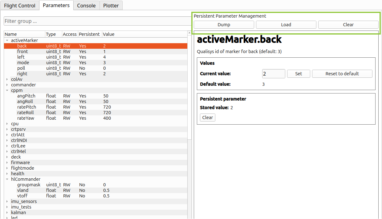
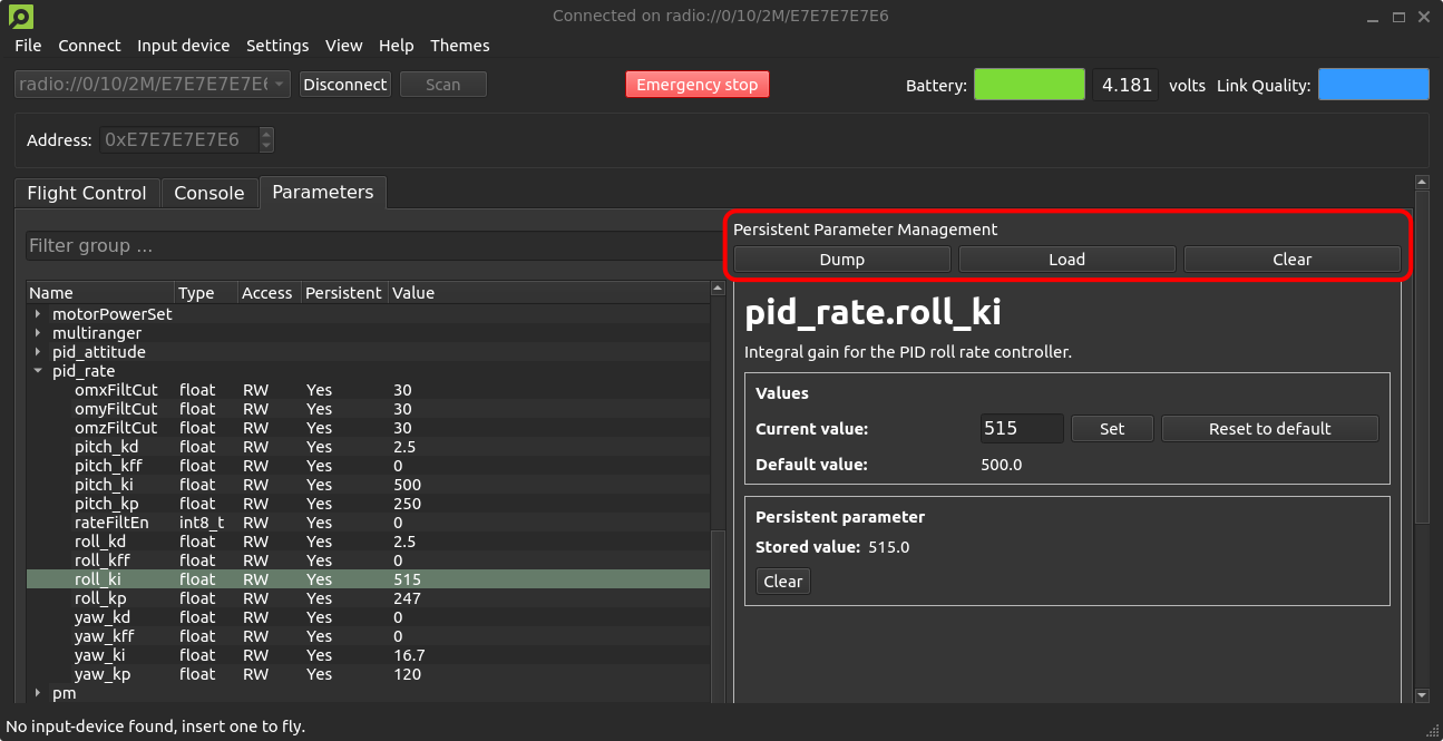
We are happy to announce the latest updates to the Crazyflie client and Python library. Major changes include improved persistent parameter management, enhanced plotting with new x-axis manipulation features, and new default logging configurations (for PID tuning). Minor updates include bug fixes and documentation improvements.
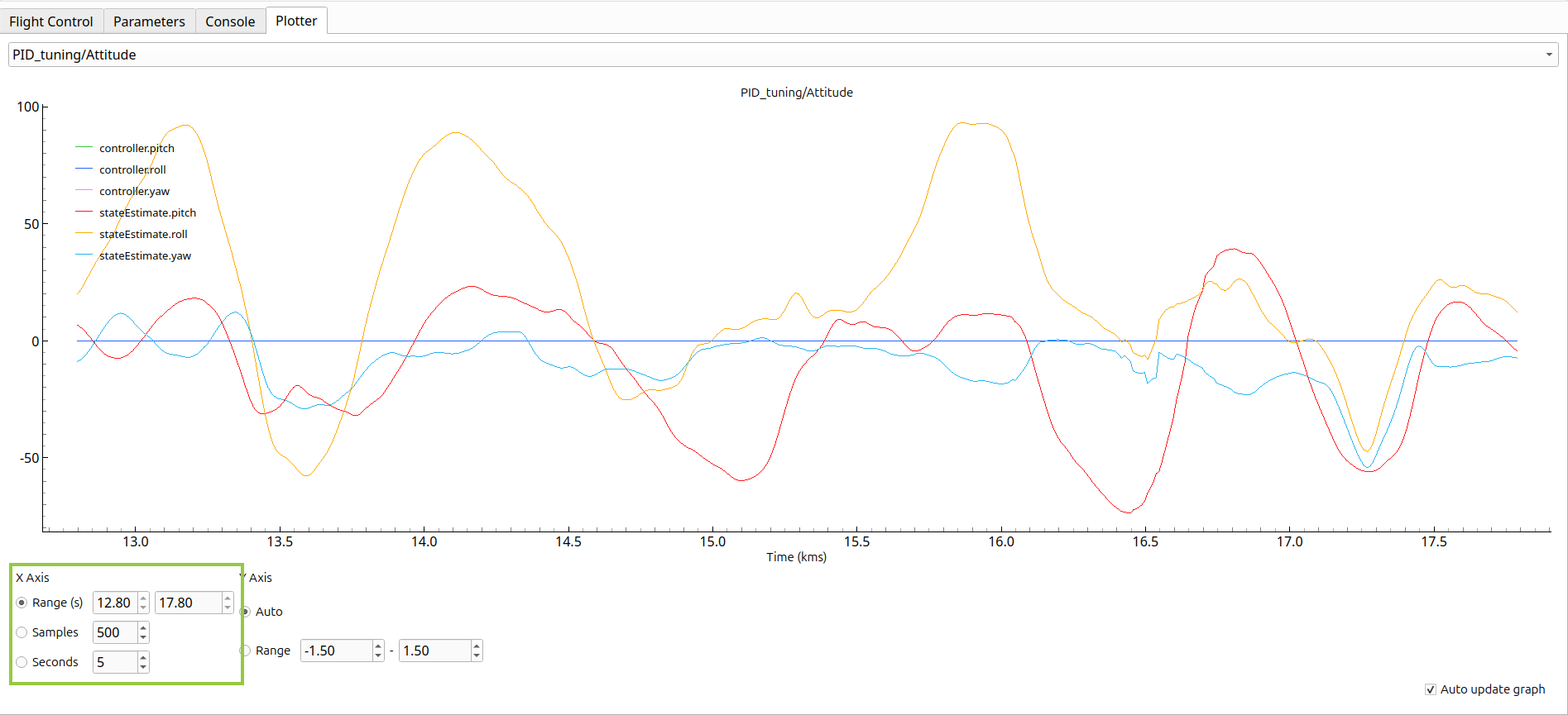
Updated plotter tab. Besides the existing option for a number of samples, users can now set x-axis limits to a number of seconds or a time range.Updated parameters tab. Users can now mass dump/load persistent parameters to/from a file, or clear all stored persistent parameters.
Simulators are one of the most important tools used in robotics research. They usually are designed for different purposes with different levels of complexity. For example, simulators with low computational overhead that are parallelizable are mainly used for either training reinforcement learning algorithms or Monte Carlo sampling for verification of task completion in a nondeterministic environment. Some simulators also use rendering engines for the graphical display of models and the environment or when cameras are intended to be used in the robotics platform. Simulation is also useful for the development and deployment of new robotics firmware features where the firmware is compiled on a test machine and run in the loop with a simulated sensor suite. This simulator configuration is known as software-in-the-loop (SITL) because the vehicle firmware is intended to be run in the loop with the simulated vehicle physics and/or rendering engine. This feature is supported by autopilot suites such as PX4, ArduPilot, CogniPilot, and BetaFlight. This feature is not officially supported yet for Crazyflies because it requires a large overhaul of the firmware to be able to compile on a desktop machine and interact with different simulators such as Gazebo, Webots, PyBullet, CoppeliaSim, Isaac Sim, or Unreal Engine.
CrazySim
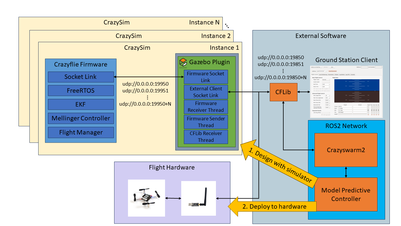
Last summer I began working with Crazyflies and noticed this Crazyflie simulator gap. I stumbled on a community-developed project for Crazyflie SITL called sim_cf. This project is exactly what I was looking for. However, the firmware used by the project is from July 2019 and the official firmware has had over 2000 commits made since then. The project also uses ROS 1, Gazebo Classic, and doesn’t support the Crazyflie Python library (CFLib). Using this project as a starting point I set out to develop CrazySim–a Crazyflie SITL project that doesn’t require ROS, uses Gazebo Sim, and supports connectivity through CFLib. Using CFLib we can connect the simulator to external software such as Crazyswarm2 or the Crazyflie ground station client. Users test their control algorithms in the external software using the simulator interface before deploying to real flight hardware.
An example of offboard model predictive control design and deployment workflow using CrazySim.
Using the Crazyflie Client for PID Tuning
We have also provided a modified Crazyflie client for CrazySim support. The Crazyflie client is a cool tool for testing a single drone in hardware. We can perform command based flight control, look at real time plots, save log data, and tune PID values in real time. The PID values are typically tuned for an out of the box Crazyflie. However, when we modify the Crazyflie and add extra weight through batteries, decks, and upgraded thrust motors then the behavior of the Crazyflie will change. If a user wants to tune a custom Crazyflie setup, then they can add additional models in this folder with their own motor and mass properties. Then they just need to add it to the list of supported models in either of the launch scripts. There is already an example model for the thrust upgrade bundle. Documentation for installing the custom client can be found here.
PID tuning a simulated Crazyflie using CrazySim on the Crazyflie PC client.
Crazyswarm2
We can now connect to the simulated Crazyflie firmware using CFLib. Therefore, we can set up a ROS 2 interface through Crazyswarm2 for swarm command and control through ROS 2 topics and services. To do this we first startup the drones using any of the launch scripts.
Then, we bring up Crazyswarm2 after setting up the configuration file for the number of drones chosen.
ros2 launch crazyflie launch.py backend:=cflib
We demonstrate an example of how we can control a swarm of drones using Crazyswarm2 GoTo service commands.
Crazyswarm2 GoTo service commands using CrazySim.
ICRA 2024
CrazySim is also being presented as a paper at the 2024 IEEE International Conference on Robotics and Automation in Yokohama, Japan. If you are attending this conference and are interested in this work, then I invite you to my presentation and let me know that you are coming from this blog post after. For the paper, I created a multi agent decentralized model predictive controller (MPC) case study on ROS 2 to demonstrate the CrazySim simulation to hardware deployment workflow. Simulating larger swarms with MPC may require a high performance computer. The simulations in this work were performed on an AMD Ryzen 9 5950X desktop processor.
Model predictive control case study for ICRA 2024 paper.
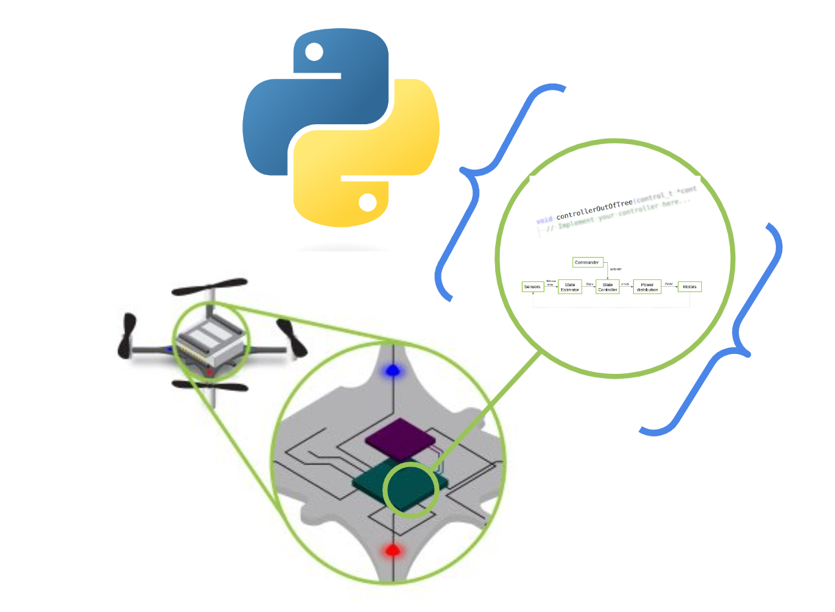
Today, we’d like to take the opportunity to spotlight a feature that’s been in our code base for some time, yet hasn’t been the subject of a blog post: the Python bindings for our Crazyflie firmware. You may have noticed it mentioned in previous blog posts, and now we’ll delve into more detail about what it is, how we and others are utilizing it, and what its future holds.
What are the Python bindings?
Language bindings, in essence, are libraries that encapsulate chunks of code, enabling one programming language to interface with another. For instance, consider the project Zenoh. Its core library is crafted in Rust, but it offers bindings/wrappings for numerous other languages like Python, C/C++, and so on. This allows Zenoh’s API to be utilized in scripts or executables written in those languages. This approach significantly broadens the functionality without necessitating the rewriting of code across multiple programs. A case in point from the realm of robotics is ROS(1), which initially created all of their APIs for different languages from scratch—a maintenance nightmare. To address this, for ROS 2, they developed the primary functionality entirely in C and provided wrappers for all other programming languages. This strategy eliminates the need to ‘reinvent the wheel’ with each iteration.
Rather than redeveloping the firmware in Python, our esteemed collaborators Wolfgang Hönig and James Preiss took a pragmatic approach. They selected parts of the Crazyflie firmware and wrapped them for Python use. You can see the process in this ticket. This was a crucial step for the simulation of the original Crazyswarm (ROS1) project and was continued for its use in the Crazyswarm2 project, which is based on ROS 2. They opted for SWIG, a tool specifically designed to wrap C or C++ programs for use with higher-level target languages. This includes not only Python, but also C#, GO, Javascript, and more, making it the clear choice for implementing those bindings at the time. We also strongly recommend checking out a previous blogpost by Simon D. Levy, who used Haskell to wrap the C-based Crazyflie Firmware for C++.
Where are the Python bindings being used?
As previously mentioned, the Crazyswarm1 & 2 projects heavily utilize Python bindings for testing key components of the firmware (such as the high-level commander, planner, and controller) and for a (hybrid) software-in-the-loop simulation. During the project’s installation, these Python bindings must be compiled so they can be used during simulation. This approach allows users to first test their trajectories in a simulated environment before deploying them on actual Crazyflies. The advantage is that minimal or no modifications are required to achieve the same results. While simulations do not perfectly mirror real-world conditions, they are beneficial because they operate with the same controller as the one used on the Crazyflie itself. In our own Crazyflie simulation in Webots, it’s also possible to use these same bindings in the simulator by following these instructions.
Three controllers (PID, Mellinger, and Brescianini), intra-drone collision avoidance, and the high-level commander planner have all been converted into Python bindings. Recently, we’ve added a new component: the Extended Kalman Filter (EKF). This addition is ideal as it allows us to test the filter with recorded data from a real Crazyflie and experiment with different measurement models. As we discussed in a previous blogpost, estimators are complex due to their dependence on chance and environmental factors. It’s beneficial for developers to have more control over the inputs and expected outputs. However, the EKF is deeply integrated into the interconnected processes within the Crazyflie Firmware. After a significant refactoring effort, these were added to the bindings by creating an EKF emulator (see this PR). This enabled Kristoffer to further enhance the TDOA outlier filter for the Crazyflie by emulating the full process of the EKF, including IMU data.
In addition to SITL simulation and EKF development, Python bindings are also invaluable for continuous integration. They enable comprehensive testing that encompasses not just isolated code snippets, but entire processes. For instance, if there’s a recording of a Crazyflie flight complete with sensor data (such as flow, height, and IMU data), and it’s supplemented with a recorded ground truth (from lighthouse/mocap), this sensor data can be fed into the EKF Python binding. We can then compare the outputted pose with the ground truth to verify accuracy. The same principle applies to the controllers. Consequently, if any changes are made to the firmware that affect these crucial aspects of Crazyflie flight, these tests can readily detect them.
If you like to try the python bindings tests for yourself, clone the Crazyflie-firmware repo and build/install the python bindings via these instructions. Make sure you are in the root of the repository and run: python3 -m pytest test_python/. Mind that you might need to put the bindings in the same path with export PYTHONPATH=<PATH_TO_>/crazyflie-firmware/build:$PYTHONPATH (please see this open ticket)
The next steps of the python bindings
We’ve seen how Python bindings have proven to be extremely useful, and we’re keen to further expand their application. At present, only the Loco positioning system has been incorporated into the EKF part of the Python bindings. Work is now underway to enable this for the Lighthouse system (see this draft PR). Incorporating the Lighthouse system will be somewhat more complex, but fortunately, much of the groundwork has already been laid, so we hope it won’t be too challenging. However, we have encountered issues when using the controller bindings with simulation (see this open ticket). It appears that some hardware-specific timing has been hardcoded throughout the PID controller in particular. Therefore, work needs to be done to separate the hardware abstraction from the code, necessitating additional refactoring work for the controller.
Recent projects like Sim_CF2 (see this blogpost) and Crazysim (see this discussion thread) have successfully compiled the Crazyflie firmware to run as a standalone node on a computer. This allows users to connect it to the Crazyflie Python library as if it were an actual Crazyflie. This full Software-In-The-Loop (SITL) functionality, already possible with autopilot suites like PX4 and Ardupilot, is something we at Bitcraze are eager to implement as well. However, considering the extensive work required by the aforementioned SITL projects to truly separate the hardware abstraction layer from the codebase, we anticipate that refactoring the entire firmware will be a substantial task. We’re excited to see what we can achieve in this area.
Indeed, even with a more comprehensive Software-In-The-Loop (SITL) solution, there’s no reason to completely abandon Python bindings. For developments requiring more input/output control—such as the creation of a new controller or an addition to the Extended Kalman Filter (EKF)—it’s beneficial to start with just that portion of the firmware code. Python bindings and a SITL build can coexist, each offering its own advantages and disadvantages for different stages of the development process. By leveraging the tools at our disposal, we can minimize the risk of damaging Crazyflies during development. Let’s continue to make the most of these valuable resources!
Dumping and loading persistent parameters to and from a file
We have a small quality-of-life update that will allow users to dump and load persistent parameters to and from a file that has recently been merged #PR443 and #PR706. A new persistent parameter management area is introduced to the parameters tab of the client, with buttons for dumping and loading persistent parameters, as well as clearing all stored persistent parameters from the Crazyflie. The persistent parameters are stored in .yml format, allowing for manual editing if desired. If you have any improvement suggestions please drop us a comment!
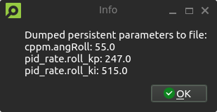
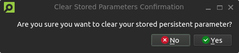
A new persistent parameter management area is introduced to the parameters tab of the client, with buttons for dumping, loading and clearing stored persistent parameters.An information dialog notifies users of the dumped persistent parameters and their values. Loading parameters will result in a similar pop-up.A confirmation dialog prevents accidental clearing of persistent parameters.
System-id code merged to master
Back in 2021, we created the system-id deck which we talked about in this blog post. It has not been officially released but a few users have gotten some PCBs and built it themselves. The functionality for the system-id deck has previously been in a branch, but as code in branches tends to become outdated, we have now moved this into the master branch utilizing the kbuild system instead. Building for the system-id deck is now as easy as doing “make sysid_defconfig” and then compiling. While talking about the system-id deck, let’s check the interest of releasing it as a product. It can help with system identification, tuning of controllers, improving efficiency etc. With enough interest there might be an economy in manufacturing it.
Out of stock
Unfortunately, we’re out of stock of Crazyflies at the moment. We expect some at the end of next week, so hopefully, you should be able to find them back in the store quickly.
Developer meeting
The next developer meeting will be on the 6th of March 2024, Arnaud will talk about the Crazyflie Client past, present and future, based on its last blog post. The client is still very useful but starts to show its age so we are looking at what should be kept, what should be improved and what should be removed. We will present what we have in mind, please come and discuss with us so we can shape the next 10 years of Crazyflie client!
The Crazyflie client has a quite long history, like a lot of things in the Crazyflie ecosystem it has been started when the Crazyflie was used alone using mainly manual control. It has evolved to follow new use-cases of the Crazyflie but it still has traces of its origins and some limitation are still there with us. Moreover, the Crazyflie client and lib are written in python, one the main goal was to make it easily cross-platform. Unfortunately making a cross platform graphical program that accesses hardware in Python has proven to be quite challenging and we feel Python is not the way to go anymore. In this blog post we would like to discuss a bit the current state of the Client and what we are looking at for the future.
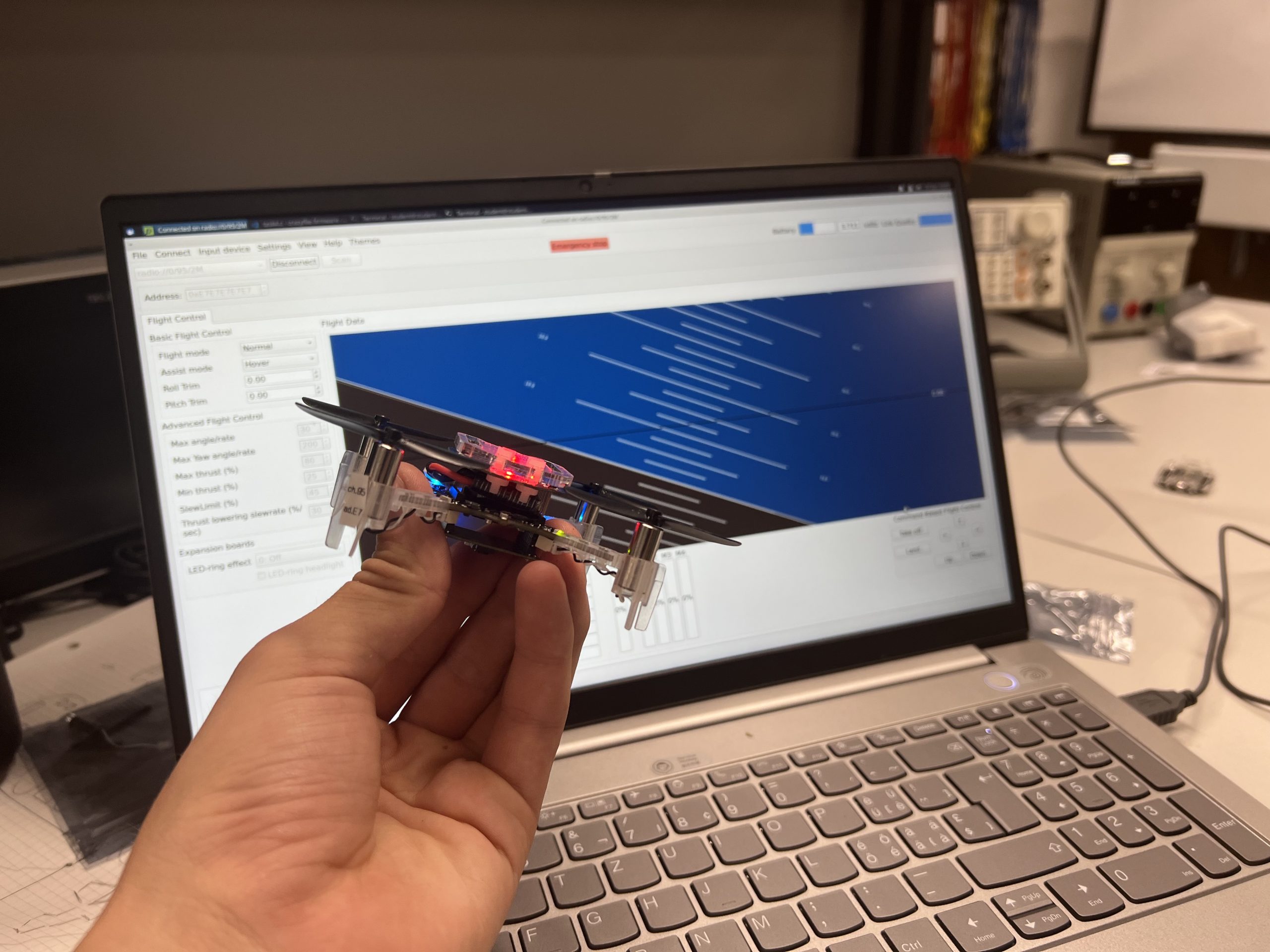
A Crazyflie connected to the CFclient
The Crazyflie client was originally design to be able to fly, inspect and work with one Crazyflie. It still serves this purpose quite well: with the client you can connect your Crazyflie, observe graphs of internal log values in real time, setup different decks and sets and store parameters. It is a very good tool to explore and work with the Crazyflie.
However, it is only working with one Crazyflie at a time will take over the radio, so another script cannot talk to the Crazyflie at the same time using the radio. Unless the script uses the ZMQ API that allows an external program to control client and so to control the Crazyflie while the client is connected and active. This functionality can be very useful but, since it is disabled by default, has not seen a lot of use.
The worst, for us, in the current client state is Python and PyQT distribution situation: we used to have an easy-to-use installer on windows, a Linux Snap package and plan for a Mac App. All these have been pretty much abandoned because they kept breaking down over time and the support weight for us was too big. So the only way to install the client is via Pip, the python package manager. This means that you already need a well setup Python environment to run the client. That is nice unless you have a Mac or a Raspberry pi: the latest MacOS broke part of the client that prevents it to run and there is no PyQT build for raspberry-pi available on PyPi. This is the kind of paper-cut that keeps happening at regular interval with distributing a Python application and that we keep having to look at.
So, we have been looking at ways to improve the situation. The Crazyflie client is more than 10 years old now, so a rewrite would not be such a crazy thing to consider. There are at least 2 angle of attack to make a new client better suited for the next 10 years of Crazyflie development:
Multi-platform and distribution
Making a multi-platform program is and will always be challenging. However, we have discovered that doing it in a dynamic interpreted language like python is even more so. The main challenge come from the fact that things tend to break on the user side depending of the user configuration: we all run a slightly different version of python, python evolve and package management evolves as well, so when things break it breaks at random depending of how up-to-date a particular system.
One solution would then be to switch to a compiled programming language. This increases the probability of finding problem at compile time and not at runtime, which means that we will hopefully be the first to know then Apple decided to change the location of one fundamental piece of library and so allow us to hopefully fix the problem before any user is impacted (assuming we can run CI on the latest version of MacOS early enough…).
So, as you might have guessed, our current idea is to write the client in Rust. We are currently looking at Tauri for the UI which is Web based. We still have ideas of also making a web-client so having a web-based IU on PC would simplify development of that.
We are not letting Python go away though, the idea is still to support Python, but to use it for what it is good at: a great language for developer and experimentation. Rust has great bindings to python so in this plan, the python lib is backed by the Rust lib.
Modularity
The other side of the current client limitation is the fact that it connects one Crazyflie taking over the radio. We actually love using the client to observe and poke the state of a Crazyflie so it would be really great to use it when writing a script or controlling a swarm with Crazyswarm. The current ZMQ implementation was designed to solve this issue, but it goes at it the wrong way around: the client becomes the gateway to the Crazyflie and must always be ON. It would be much nicer to be able to launch the client to connect and inspect a Crazyflie currently control by a script.
One design we are currently looking at would be to use use a protocol like Zenoh between the client and the lib. Basically, when connecting a Crazyflie, be it from a script or from the client, a server would be launched in the background that would handle the connection. All communication would pass through this server and so multiple programs would be able to communicate simultaneously with the Crazyflie.
This would allow us to build easily bridges to ROS to get the client to communicate with a Crazyflie currently connected in ROS. And since ROS2 is working on supporting Zenoh officially a bridge might not even be required.
As an added bonus, the Crazyflie server idea would greatly improve the situation when it comes to supporting Virtual Machines and WSL on Windows: it would move the USB connection handling to a Windows program and only require fast network connections which is something that works really well on WSL or VMs.
Conclusion
In this blog post I have tried to describe our current challenges and some way forward we see. The main message though is that we want to change things when it comes to the client, if you have wishes or ideas now is a good time to get in touch. Let’s make the next 10 years of Crazyflie client problem-free.