Hello world,
you had probably seen me from the last blog post when I first arrived. I spent this summer working here in Malmö and I can definitely say that it was one great, educative and fun experience. During the last three months I have been in Bitcraze, I was given the chance to work and develop applications and demos on the robotics subject I am most interested in, drone collaboration.
Centralized Swarm with Multiple Flying Copter
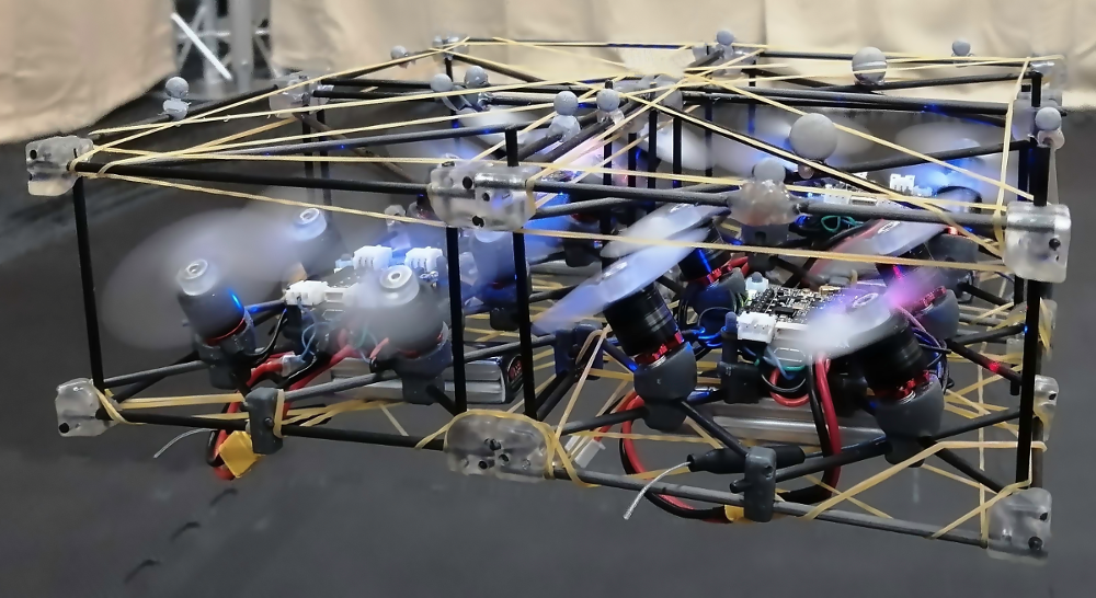
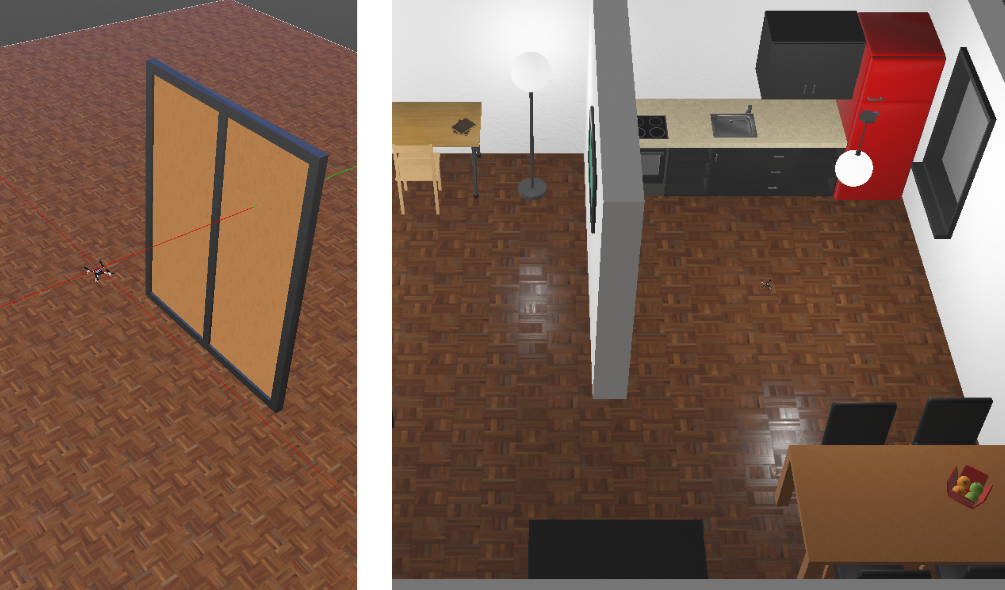
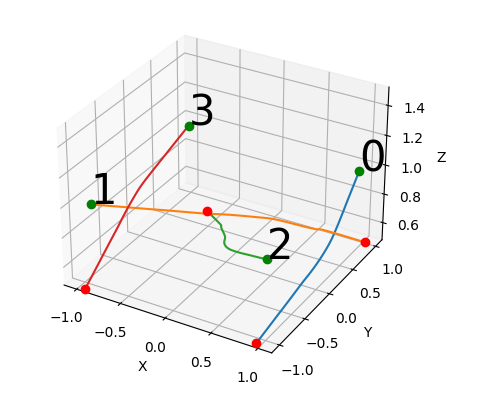
I initially started looking into the implemented swarm demo which had 7 drones charging wirelessly in 7 charging decks and one of them flying by executing a spiral trajectory until it has a low battery and another one takes its place. The original swarm demo was shown at several conferences before the pandemic hit, but my plan was to improve it by adding more quadcopters flying simultaneously. The biggest problem was the collisions and ground effect happening between them. In order to solve that I was based on this paper and the optimization engine OpEn. I solved the problem of all drones starting from a point and going to a final one without colliding and covering the minimum distance by transferring these constraints into a cost function of an optimization problem assuming a simplified model for the quadcopter. Its output is waypoints for each quadcopter to pass from. These waypoints are transformed into a trajectory(piecewise polynomial) by a custom trajectory generator based on linear algebra.
In this way, I made it possible to execute non-colliding trajectories for 4 quadcopters, upload and execute them. While executing the first trajectory, the next one was being calculated and uploaded assuming the goal of the previous one as starting point. In this way, I managed to have 4 Crazyflies flying simultaneously and landing when their battery was running out and the fully charged ones were taking their place. This mechanism with some modifications can be used as a path planner or a standalone trajectory generator from a future user by feeding it waypoints and time durations for each waypoint segment. You can find the source code here.
Decentralized Swarm with Multiple Flying Copters
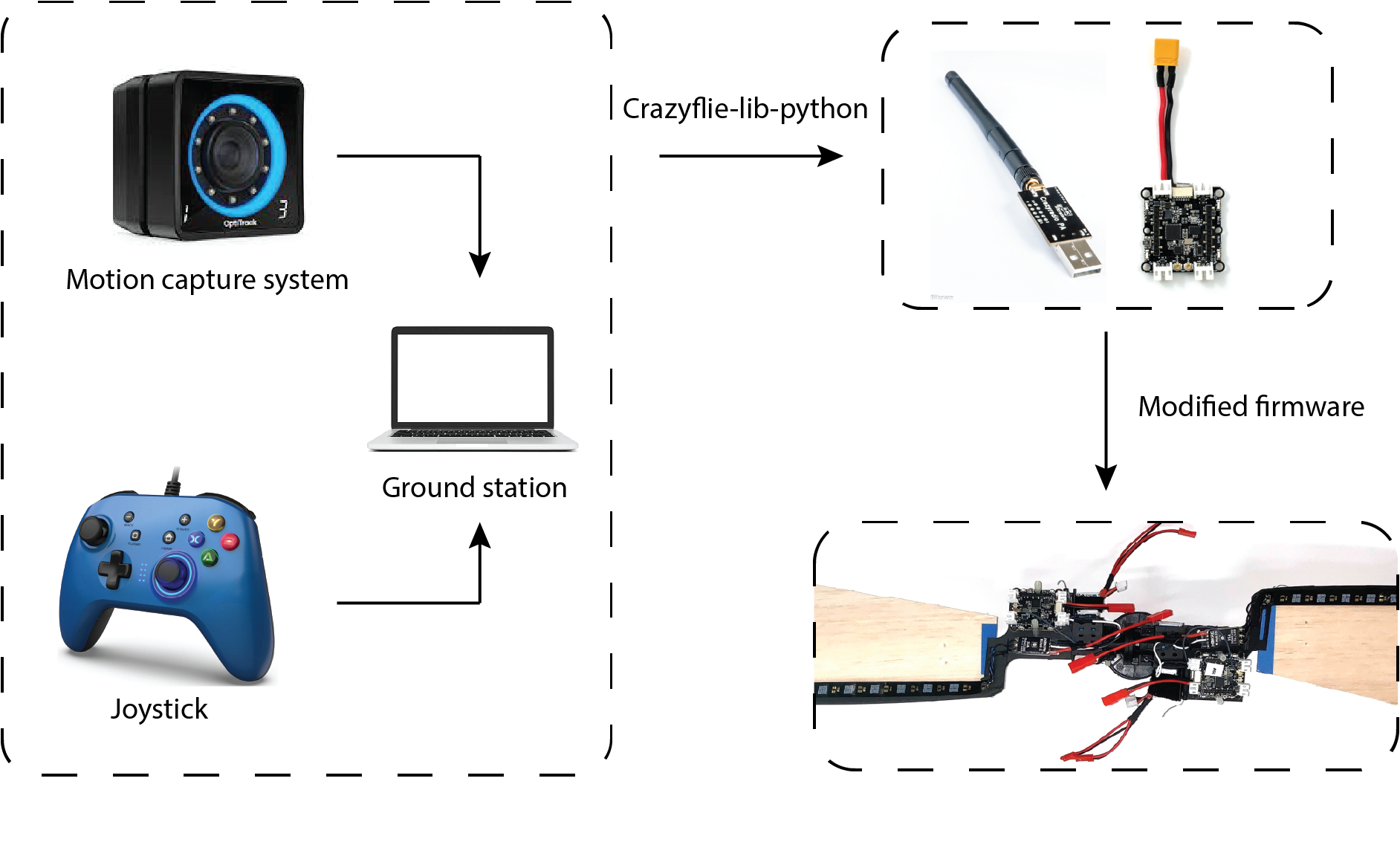
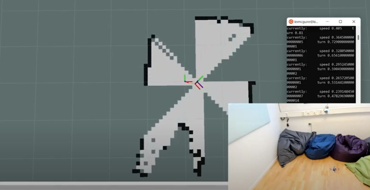
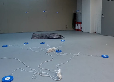
The aforementioned setup seemed to work pretty well but there was always the need of having a central PC monitoring and taking decisions for the whole swarm. So we wanted to move the architecture to a decentralized one, of which Kristoffer did some preliminary work shown at BAMdays last year. This was made possible by utilizing the onboard peer-to-peer protocol (P2P) in collaboration with the onboard collision avoidance algorithm introduced in this PR contributed by James Preiss from the University of Southern California. All the Crazyflies share their position and state through the protocol by broadcasting them at a rate of 15 Hz.
Although there were some missed packets, they could avoid each other while flying by updating the collision avoidance algorithm which is taking action between the high level and the action commander by altering its waypoints. The decisions of which drone should take off or land are also taken in a decentralized way. Whenever one copter is about to take off it enters the corresponding state and assigns itself a randomized timeout. During this timeout, if the desired number of airborne copters is achieved it goes back to idle. If not and the timeout occurs it finally take-offs. So, despite there is not an actual common decision, the swarm can be led to simple desired states like keeping the number of the drones flying constant and executing changes between the landed, charged copters and flying ones. You can find the source code here.
Token Ring Implementation
After I finished this project and since I had some extra time left I decided to work more in the P2P protocol. The need for having a robust way to communicate between the Crazyflies and a way to verify that a packet was indeed sent was obvious. A solution to this problem was offered by Christos Zosimidis and Klaus Kefferpütz from the Cooperative Control Lab in Hochschule Augsburg, namely a token ring implementation. I would really like to thank them for this collaboration and hope for future ones as well.
Specifically, the proposed token ring protocol was implemented in a modified version of the nrf-radio firmware and the Crazyradio. This protocol assumes that each Crazyflie is a node of a network and a token is passed around giving permission to each drone that has it in its possession to broadcast data. So, each time only one Crazyflie broadcasts data which leads to fewer packet collisions and losses. It can also acknowledge that a node has received the data targeting to it and then continues to others. The interface with the protocol is being done by 2 queues (TX and RX) where the user can place data that wants to send and read the RX queue to receive. The moment that this blog post is being written only the static version of it is public in the firmware, which means that the number and the id of the Crazyflies must be defined before execution and in case a copter fails the whole network fails. Although, I am currently working on a dynamic approach that is going to solve these problems
All in all, I had a great time here in Malmo despite the fact that the Swedish summer is much colder than the warm weather I was used to in Greece. I was amazed by the way things in Bitcraze work and how the whole company operates. It was a pleasure being around so creative people and I am happy that I could help even in a small way. Thank you very much for giving me the opportunity to work with you and I hope I will keep on contributing to this amazing project in the future.
Happy hacking and fly safe!