It’s been cooking on the slow burner for a long time now, the Crazyflie 2.1-Brushless, or CF21-BL in short. Ever since we got inspired by the tinypepper 1-cell brushless motor controller which showed us a small brushless ESC could be made, we got the idea of integrating brushless ESCs into the Crazyflie. Integrating the ESCs turned out to be easier then we though, but we hade more ideas, we wanted it to be efficient. Due to the FPV market and the toothpick sized category plenty of appropriate size components exist, however none is really optimized for efficiency. So we had to go back to the drawing board, contact suppliers and work with them to try and improve efficiency. This turned out to be a very time consuming task and we are now at a stage where we think we have gotten as far as we can with the resources we have.
Why go brushless?
A brushless setup is better in most aspects but it has some downsides, such as cost and complexity. The brushless motors requires a more complex design and is therefore more expensive to manufacture. It also requires a more sophisticated motor driver that also needs a larger PCB board space. On the upside we have better power to weight ratio, better longevity and efficiency to name a few. For the tiny type of brushless motors that are interesting here the efficiency gain is not so obvious though. This is mainly because it is hard to make an efficient motor driver due to the low inductance in the motors and this can definitely be further improved, perhaps with software upgrade of the ESC firmware in the future.
Let’s dive into the current specification!
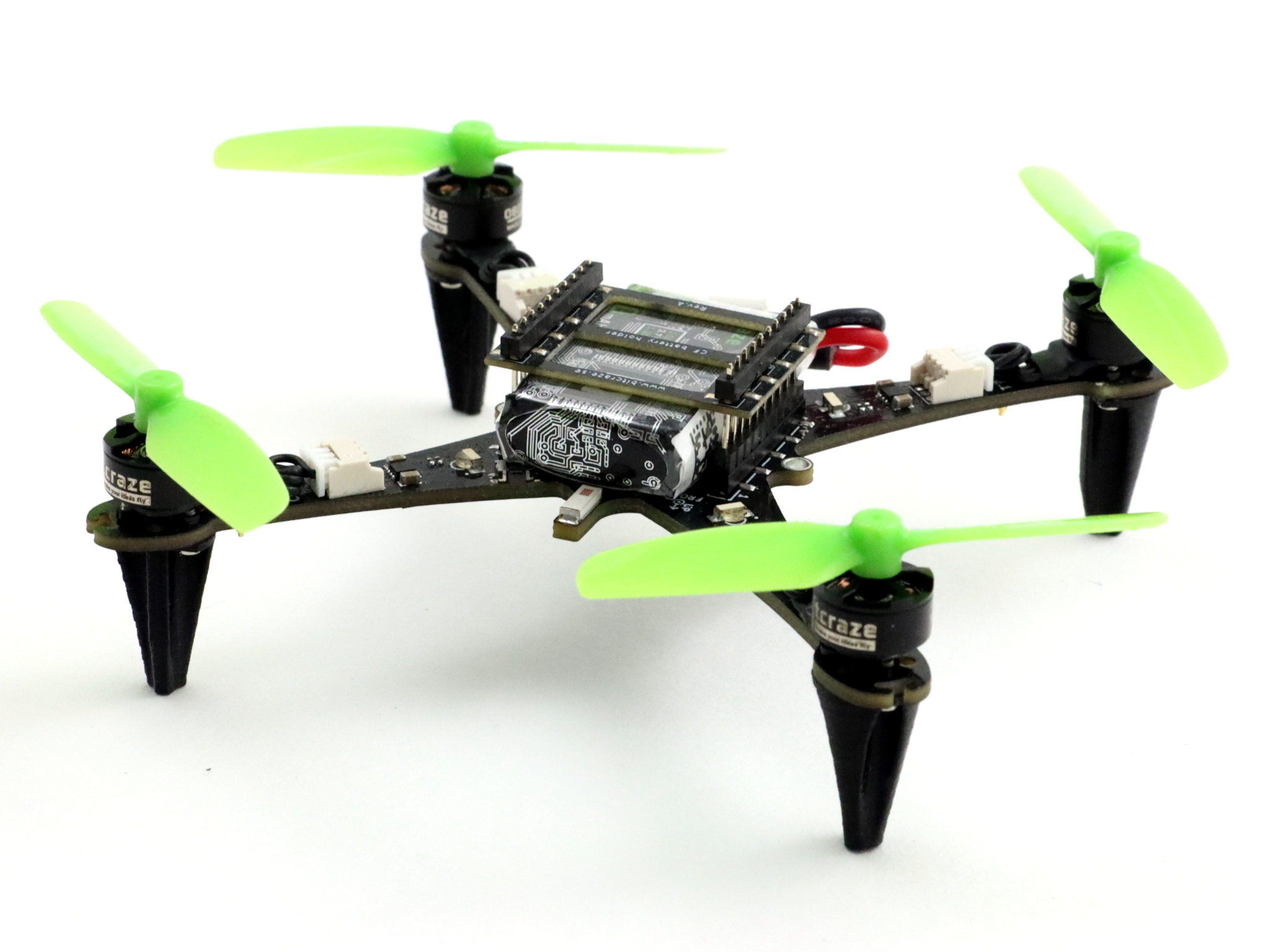
After many prototypes this is where we are at now:
Crazyflie 2.1 base design using the PCB as the frame.
4 x integrated 1-cell 5A ESCs running BLHeli_S/Bluejay
Weight: 32 grams ( including 350mA battery)
4 x 08028-10000KV high-quality motors generating up to 30 grams thrust each
Custom-designed and optimized 55mm propellers with 35mm pitch
Over 10 min hover time in 32-gram configuration (~5g/W efficency)
The added thrust and the longevity of the brushless motors are probably the key features of the CF21-BL. This will improve payload capability or agility for applications where this is needed as well as the robustness. It will come at the expense of a higher price tag though.
The Crazyflie 2.1-Brushless has come a long way but there are still many things that have to be done before it will be available in the store and it is too early to talk about any timeline, but the goal is to release it during 2024!
It seems that many of you are very interested in simulation. We might have gotten the hint when we noticed that our July’s development meeting had our best attendance so far! Therefore, we will be planning a new developer meeting to discuss the upcoming plans for supporting simulation for the Crazyflie.
Getting Started with Simulation tutorial
Perhaps you are not aware, but there is actually a Getting Started tutorial for simulation that has been available for a little over 2 months now. Unfortunately, circumstances prevented us from writing a blog post about it, but we’ve noticed that not all of you are aware of it yet!
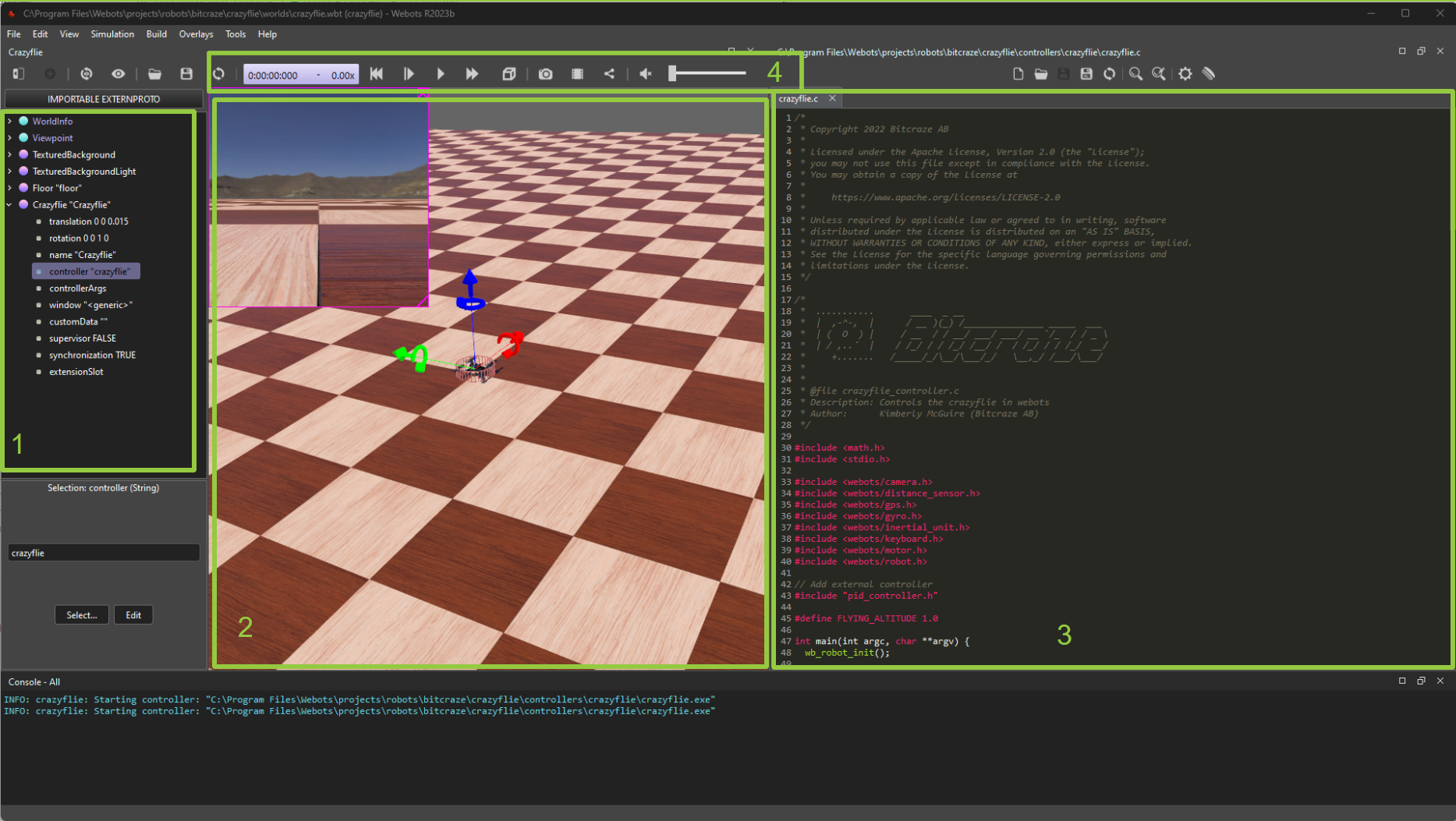
The getting-started tutorial demonstrates how to set up the Webots simulator, which already includes Crazyflie models and some cool examples:
An example that you can control the Crazyflie with the keyboard
An example that the Crazyflie does wall following autonomously
The tutorial concludes with instructions on how to edit these controllers. Alternatively, you can choose to run the files directly from the crazyflie-simulation repository. After completing the tutorial, you can explore the simulation repository documentation for more information and to access additional examples.
Upcoming plans
With so many plans and so little time! This is a common phrase at Bitcraze, and it’s a symptom of being an overly ambitious, but too small, team. By the way, we are still looking for more people :). Nonetheless, we have big plans to take our Crazyflie simulation to the next level:
ROS 2 Crazyflie model for Webots: The Crazyflie has been a part of the Webots standard robots for 2 years now, but we still need to implement the Crazyflie into the Webots ROS 2 repository.
Better (new) Gazebo support: Currently, we only have a very simple example for Gazebo, which is limited to motors with no control input. Working with the C++ API can be a bit challenging, so it might be worth considering the use of ROS 2 in the loop here. Let’s see what comes out of it.
Integration into Crazyswarm2: Once the Webots ROS2 node has been released, integrating the Crazyflie simulation into Crazyswarm2 will become more straightforward.
Improvement to the Python bindings: We’ve had Python bindings for controllers and the high-level commander for a while. Recently, we also added Python bindings for the estimator (currently for loco positioning only). However, there are still some issues to address with the Python bindings for the controllers due to timing issues with the simulators.
Linking with our CFLIB: Currently, both Webots and the Crazyflie Python library use entirely different APIs. This means that these scripts are not compatible and you’ll need to be creative not to reuse new code. However, wouldn’t it be nice to use a python example from the python library with a --sim and that it would actually control the Crazyflie in the simulator instead?
Of course, there are probably more improvements that we haven’t thought of yet, but that’s why we have developer meetings!
Come and join us at the Developer meeting.
We will be hosting another developer meeting on November 1st at 15:00 Central European Time (accounting for the time-shift from summer to autumn). You can find details on how to join in the discussion thread here.
Just for your information, I (Kimberly) am the main driving force behind our simulation efforts. However, I’m currently on partial sick leave and will soon be on full leave for a while. I kindly ask for your patience with the pace of ongoing developments. Remember, it’s an open-source project, so if you’d like to contribute and help out, we would greatly appreciate it :)
We talked about it before the summer, and it’s finally here! The 350 mAh battery is now available in our shop. It implies some changes in the products we offer, so here is a breakdown of what’s new:
It is more powerful than the 250 mAh battery that comes with your Crazyflie. We based it on the Tattu 350mAh 3.7V 30C 1S1P but with some custom works like gold connectors, tailored wire length, and awesome Bitcraze graphics on it. On top of the added power, the upgrade has higher capabilities, (30C burst current, which is more than 10 Amp) and higher energy density (~130 Wh/kg instead of ~105 Wh/kg). It all means that this could boost your hover time up to 10 minutes, and you’ll have more punch during acceleration! It is, though, more expansive than the 250 mAh.
The pin headers
The 350 mAh is thicker than the stock battery, which means you would need longer pin headers in order to snug it onto your Crazyflie. For that, there are now 9mm pin headers available in the shop. This means that now, you can get 3 different male connectors:
the 8+14mm is the one that comes with your Crazyflie kit. It’s meant to be phased out at some point. It allows to fit 1 or 2 decks and the 250 mAh battery.
the 9+15mm is slightly longer and is available in the shop – both as a spare part and in the upgraded battery bundle. It allows to fit 1 or 2 decks and the 350 mAh battery.
the male long connector: the longest pin of all, it’s the one that allows you to fit 3 decks.
Since it makes more sense to have slightly longer pins, the male connectors as spare parts are now slightly longer ones than those you get in your Crazyflie kit.
If you’re not sure, you can always buy the upgraded battery bundle that offers the 350 mAh battery with the right pin headers.
Bundles
The 350 mAh battery is much more suited for swarms than the 250 mAh, that’s why we’re planning on having an upgraded offer for our swarm bundles. In the coming week, both the Lighthouse and the Loco Swarms will be fitted for the updated offer. That would mean that it will include the new batteries with the right pin headers as well – there will be a slight price increase to match the price of the batteries.
Bare PCB
But that’s not the only surprise waiting for you in the shop: you can now also buy a spare Crazyflie PCB! We thought it would be good to have this option in the store – in case you have crashed too many times and you only just need the PCB!
Right now, it may seem a little confusing, between our different propellers, batteries, or pin headers. It’s mainly because we are trying to, slowly, build up a better, upgraded offer – which will, eventually, culminate in an upgraded Crazyflie 2.1, where the 47-17 propellers and the 9mm pin headers are standards. We’re also planning to publish a guide to help you quickly figure out what would best suit your needs!
Today, Suryansh Sharma from TU Delft presents the open-source Gimbal they devised. Enjoy!
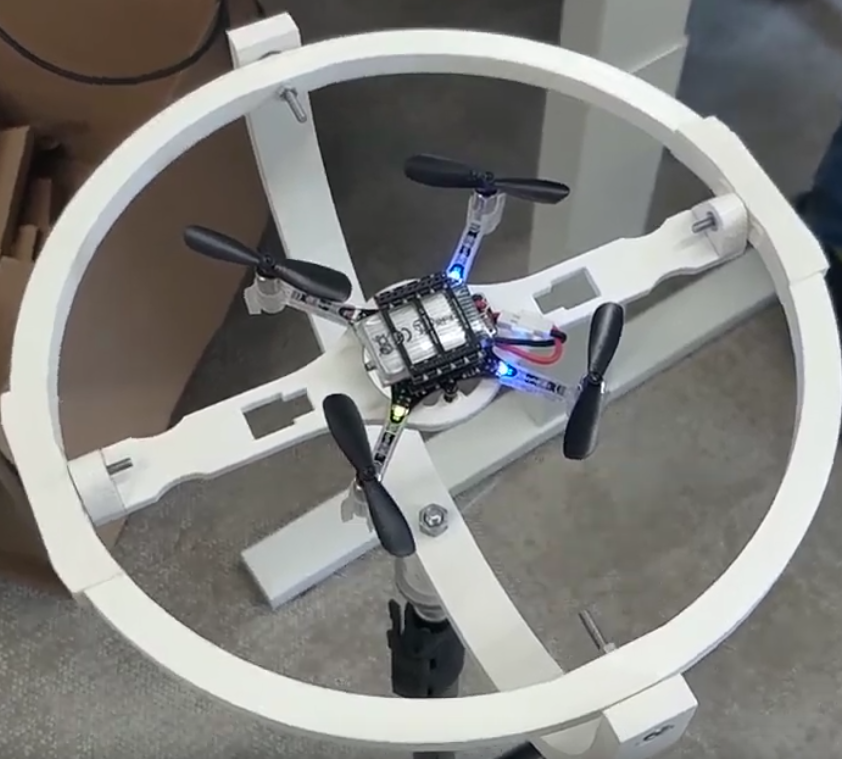
Crazyflies (and other drones in this weight class) are extremely fun to fly and prototype with! But if you are also a scientist or tinkerer and not a well-skilled drone pilot then you might struggle with flying these platforms especially when testing new control loops or experimental code. While crashing also teaches a lot about the behavior of the system, sometimes we are interested in seeing the system dynamics without breaking the drone.
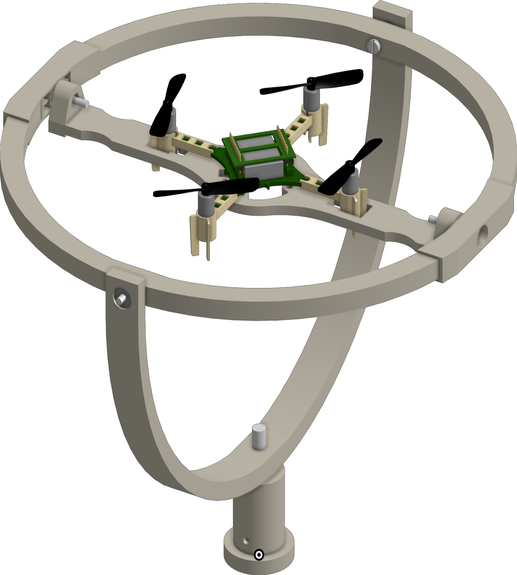
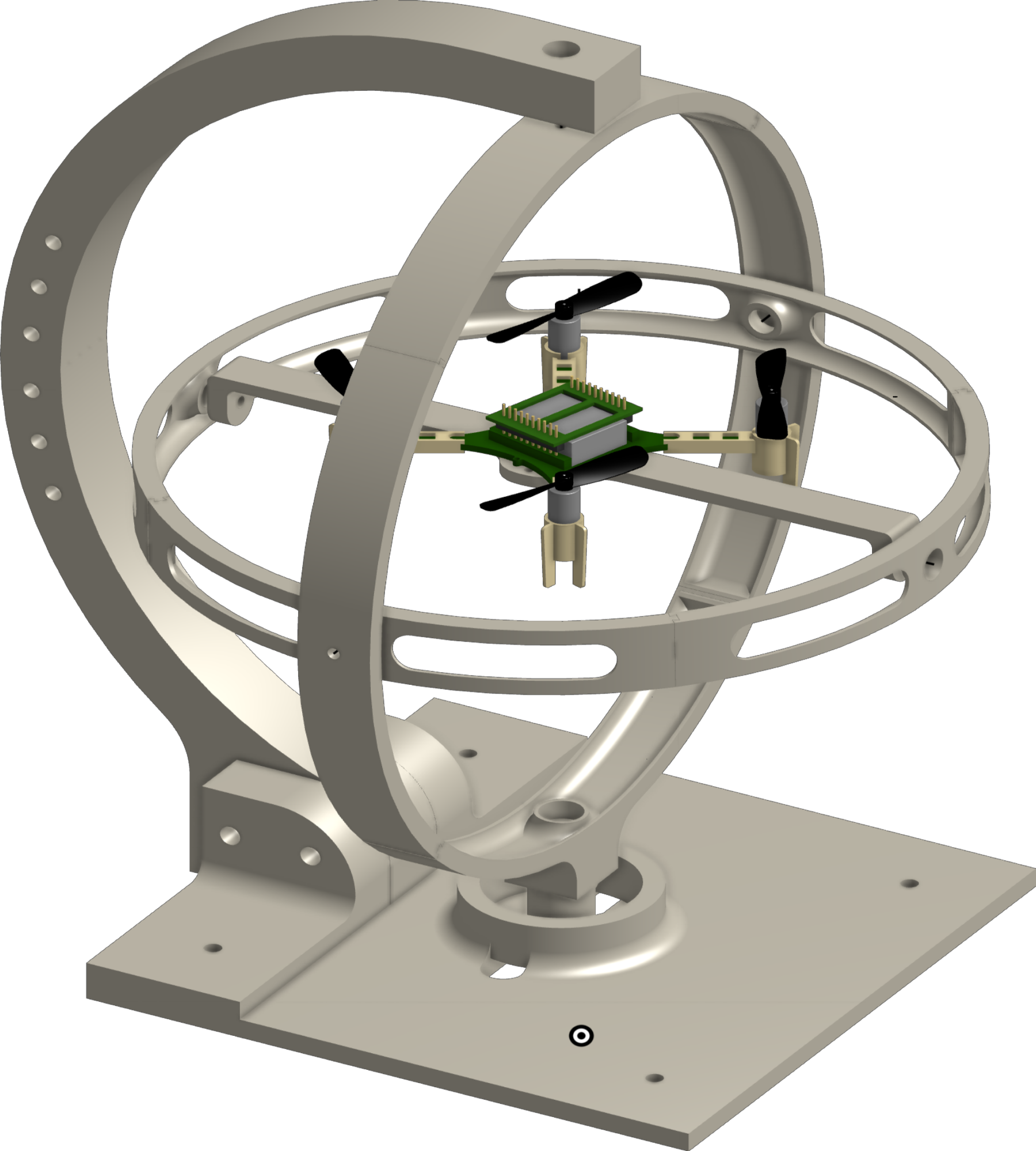
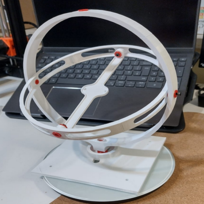
Currently, doing this for such small drones is not easy. We need something lightweight and still accessible. To solve this, we made Open Gimbal: a specially designed 3 degrees of freedom (DoF) platform that caters to the unique requirements of these tiny drones. We make two versions, (a) Tripod version which can be mounted on a camera / light tripod with a screw thread of sizes 1/4-20 UNC or 3/8-16 UNC (b) Desktop version which can be placed on a table top.
Tripod VersionDesktop VersionCAD models of the different Open Gimbal versions you can 3D print and use.
Our approach focuses on simplicity and accessibility. We developed an open-source, 3-D printable electro-mechanical design that has minimal size and low complexity. This design facilitates easy replication and customization, making it widely accessible to researchers and developers. The platform allows for unrestricted and free rotational motion, enabling comprehensive experimentation and evaluation. You can see the movement from the CAD version below:
Degrees of Rotational freedom that Open Gimbal provides
You can also check out the interactive CAD model and see how the gimbal moves here. All of the 3D model files as well as the BOM and instructions for assembly can be found in our repository here.
In our publication, we also address the challenges of sensing flight dynamics at a small scale. To do so, we have devised an integrated wireless batteryless sensor subsystem. Our innovative solution eliminates the need for complex wiring and instead uses wireless power transfer for sensor data reception. You can read all about how we do this in our paper here.
If you do end up using the platform for research then you can cite us using the details below:
@ARTICLE{10225720, author={Sharma, Suryansh and Dijkstra, Tristan and Prasad, Ranga Venkatesha}, journal={IEEE Sensors Letters}, title={Open Gimbal: A 3 Degrees of Freedom Open Source Sensing and Testing Platform for Nano- and Micro-UAVs}, year={2023}, volume={7}, number={9}, pages={1-4}, doi={10.1109/LSENS.2023.3307121}}
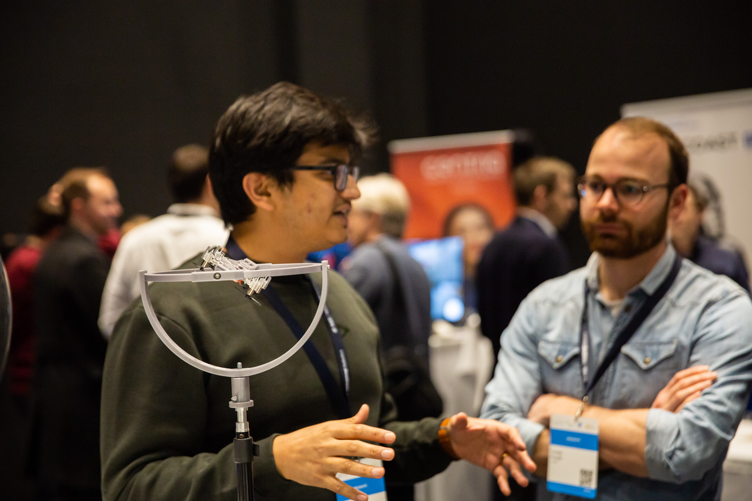
Open Gimbal at European Robotics Forum 2023 in DenmarkOpen Gimbal in use at Prof. Leszek’s lab in PolandOpen Gimbal at TU Delft, NetherlandsOpen Gimbals with Crazyflies mounted in the wild!
I hope that you find the Open Gimbal useful! Feel free to reach out to me at Suryansh.Sharma@tudelft.nl if you have any ideas/questions or if you end up making an Open Gimbal yourself!
For this months developer meeting we will be discussing the increasing complexity of the deck subsystem, talking about the challenges we see moving forward as well as discussing some possible solutions. In the blog post this week I’ll be discussing the first part, some of the challenges moving forward.
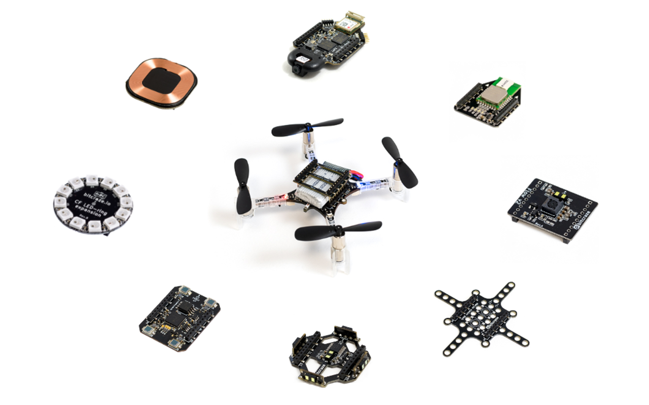
After releasing the Crazyflie Nano Quadcopter back in 2013 we realized we wanted something more than the small expansion connector we placed there. Sure, it was possible to attach more electronics (and we did) but mechanically, electrically, and software-wise it was a hassle. So when we got around to working on the Crazyflie 2.0 in 2014 we were really happy with the new expansion connector. The goal was to offer users new hardware solutions as they became available as well as giving the possibility to create customized hardware configurations. It supported multiple buses, different heights for the decks, top and bottom attachment, automatic detection, and last, but not least, it held the battery in place. Initially, we released a few decks, but over the years there have been many more. Some are very simple, like the breakout, and some are very complex, like the AI deck.
Although we’re still very happy with the deck subsystem, we’re starting to see some challenges moving forward as deck complexity increases. Some of these issues are:
Resource sharing in the STM32: Mainly DMA conflicts between different peripherals, like conflict for DMA using DSHOT on the Crazyflie Bolt and the WS2812b driver for the LED-ring.
Bus arbitration and performance: Some decks make excessive use of some buses, which can cause issues with certain combinations like the LPS deck and micro-SD card deck.
Deck combinations and pins: As more interesting decks are released and we’re able to carry more weight, users want to combine more decks. Although we try to be smart with pin allocation there’s a limit on how you can combine the decks.
MCUs on decks: With increased complexity also comes separate MCUs on decks. Although working well for offloading the main MCUs on the Crazyflie, the complexity quickly increases both for usage and for development. This is something we’ve seen with the AI deck for instance, which contains 2 MCUs.
The challenges above are something we discuss from time to time around the office, often ending up at a whiteboard pitching various ideas. The most popular solution (and therefore the most likely one becomes reality) is moving complexity off the Crazyflie and onto MCUs placed on the various decks. This would probably solve most of the challenges with the first three points, but obviously worsen the last point above.
So the question quickly becomes, how do we work with multiple decks with one (or more) MCUs without the situation becoming too complex? Something often heard in embedded is that for each MCU added the complexity grows exponentially. From experience, we can say that this isn’t so far off.
With the new Crazyradio 2.0 out, discussions on new protocols, the possibility of a library rewrite, new deck prototypes and more payload capabilities, it’s becoming more clear how this would fit in. We still haven’t decided on what solutions we’re using, but we do have a bunch of ideas that we think would fit together to meet these challenges moving forward. On Wednesday I’ll continue to discuss some of these challenges in our monthly developer meeting and also discuss some of the suggested solutions. We’re also more than happy to hear comments about this from our users. If you’re interested in joining the discussion you will find the link here. We hope to see you there!
It’s been some time now that we’ve tried to grow the Bitcraze team. Since we’re a small team, it’s been hard to put the time and energy into recruiting; and even though we’ve been looking for a new Bitcrazer for a long time, things haven’t progressed as much as we liked.
That’s why we’ve got some help. We are now working with a recruitment agency to help us reach the right people, and their insights and advice have been of great value in us figuring out exactly what kind of person we wanted, and how to phrase it in the right way to get the right person.
So we now have a new job post, that you can read here in its entirety, but which I will summarize here:
We’re looking for a production and quality manager – embedded developer. Someone that is not only a skilled embedded developer, but is also interested in our products’ production: running it, synchronizing with our partner in China, developing production tests… Having a passion for technology, production and quality is a big plus.
As usual, no roles is set in stones here at Bitcraze. Being part of a small company means that everyone has the opportunity to be involved in all parts of it ; we get to build the company we work in. With that comes freedom and responsibility! The way we work is unlike any other, and we know from the Covid experience that working remotely is nearly impossible for our process. That’s why that person should be ready to move to Malmö, Sweden. But, as I’ve explained in a precedent blogpost, coming to work at Bitcraze comes with great advantages.
While this role is one that we’re currently actively trying to fill, you’re always welcome to openly apply for a job at Bitcraze. Don’t hesitate to send us an email at jobs@bitcraze.io and tell us who you are!
One detail that has its importance: unfortunately, hiring someone from outside the EU takes time and energy; with a lot of paperwork and a much longer timeframe. That’s why we’d prefer if the person we hire has EU citizenship.
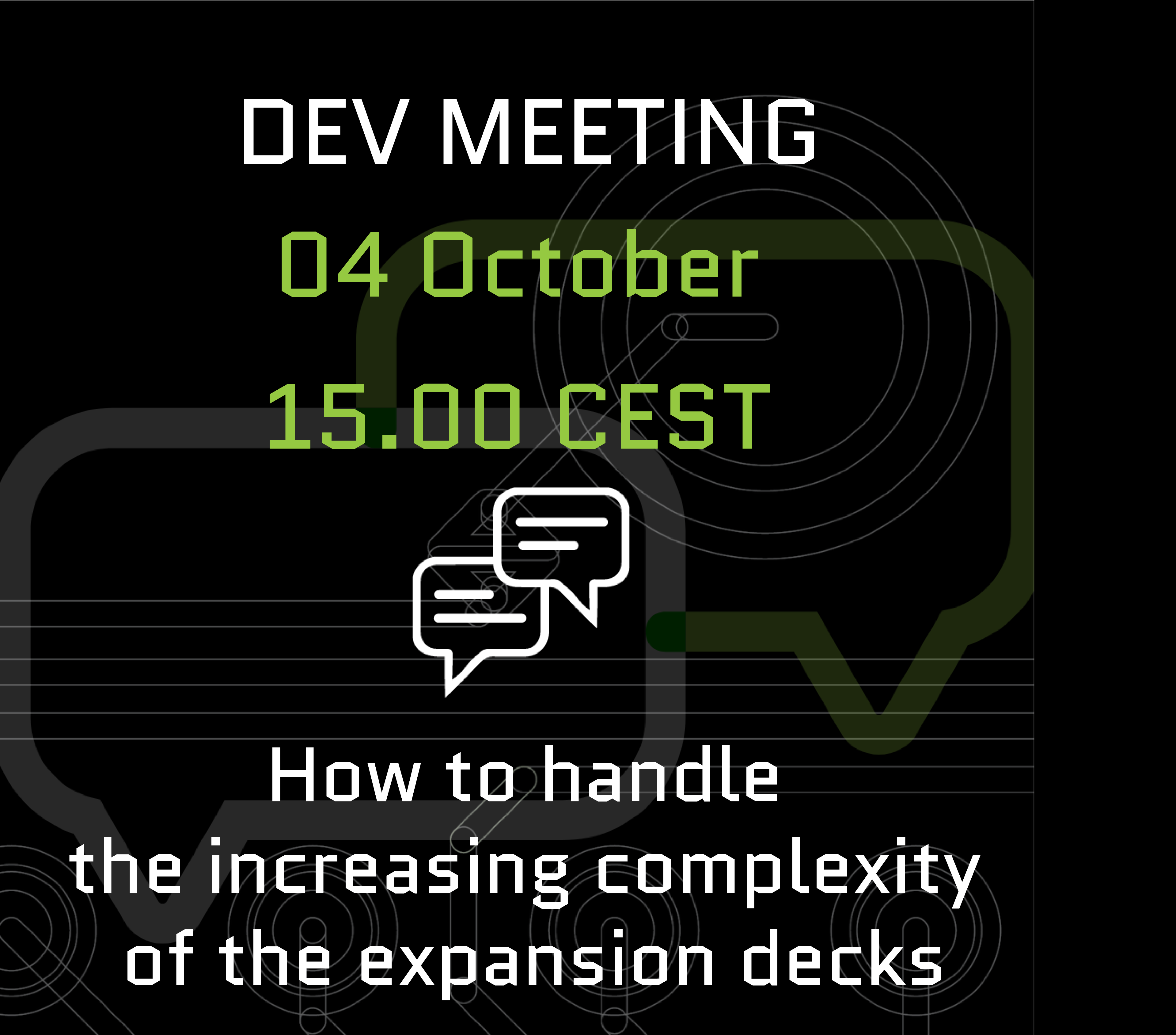
Dev meeting
Next week is already time for our next dev meeting! This time, we will talk about how to handle the increasing complexity of the expansion decks. We’ve seen some issues with the increasing complexity of the expansion decks, and had some ideas for solutions moving forward that we want to share!
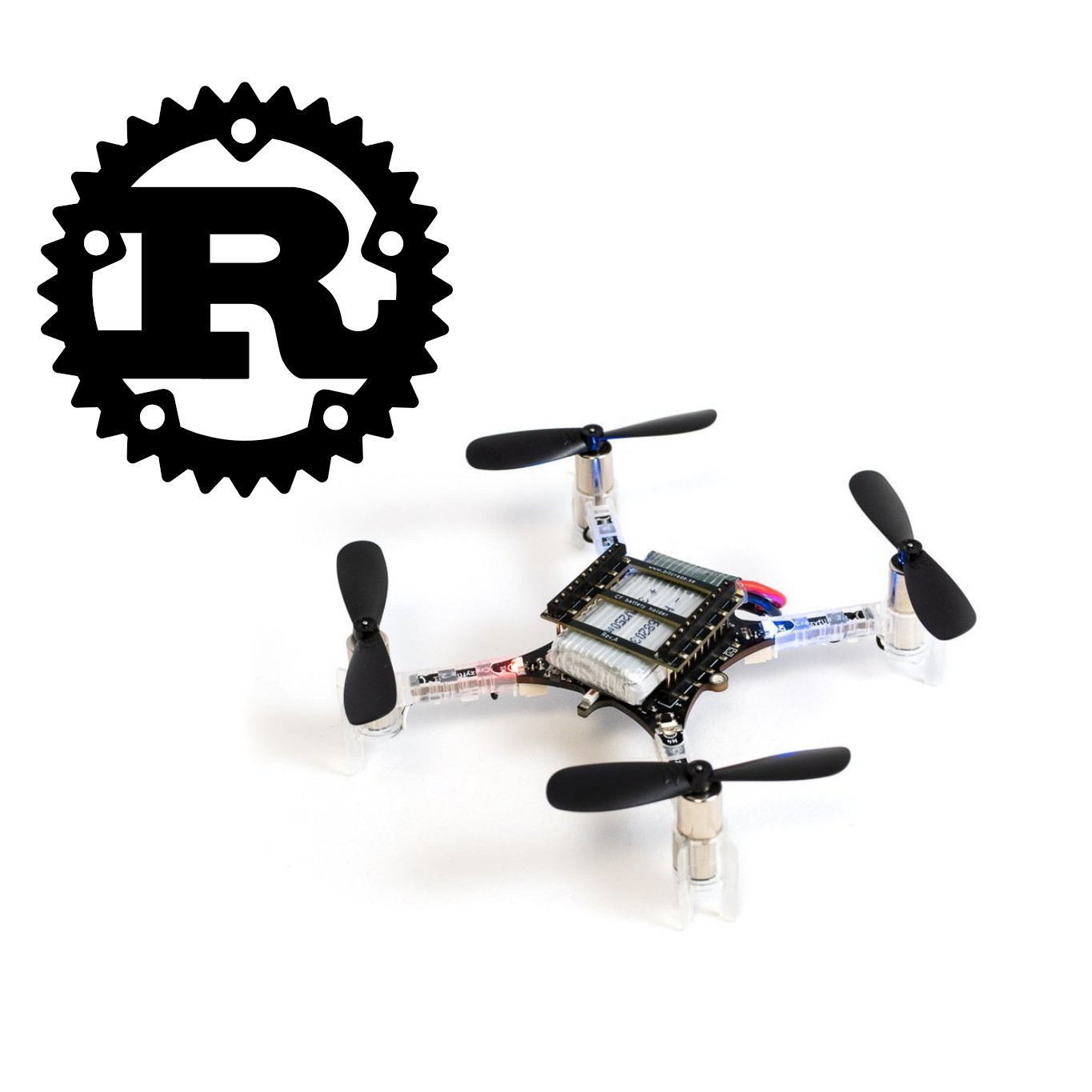
Lately we have been thinking about and using the Rust programming language more at Bitcraze. In this blog post we will talk a bit about our current use, current experiments and potentially future use and how it will affect our ecosystem.
Rust is a system programming language that has good performance, is reliable and productive. Practically it means that it can be used to run small and fast code (well suited for embedded systems for example), be quite fun to write, and be reasonably sure that if it compiles, it works.
On servers
Over the year we have written and maintained a server system to handle a lot of things related to production and sales. This system is the one generating shipping quote when you order in our store, telling us that there is an order, printing packing lists and shipping labels for the order as well as keeping track of stock and telling us when it is time to order a new batch of product.
This system is used every day and has been invaluable to how we work at Bitcraze. It is mostly implemented as NodeJS micro services.
We have started writing new functionality for it in Rust instead of in a new monolithic service. This has been a great experience, not always easy, but the bonus is that once it compiles there has been almost no run-time error. This has allowed us to gain experience with Rust in an environment that is well documented: servers on PC.
In test rigs
Every manufactured product must be tested: there is no guarantee a board will work when it exits the re-flow oven. This test usually happens in a test-rig that measures and affects various signals on the board (look under your favorite Bitcraze deck and you will see test-points: round pads designed to enter in contact with test probes). Attached to this test-rig is a computer running our test software. We have used a Python-implemented test software for all our products so far and this system started showing its age by being harder and harder to work with and, most importantly, hard to deploy on computers in the factory.
For Crazyradio 2.0, we decided to completely re-write our test software, in Rust of course :-). The design of the test framework is very inspired by OpenHTF: the framework provides the basic architecture of the test and the executor, tests are implemented in Rust and implement all the required test phases. Test statuses are streamed to a web browser as well as to our server (to one of the newer parts of our server system written in Rust). There are two big advantages of using Rust in this application: making sure the test software works reliably and without errors saves a lot of time during manufacturing and helps make sure no bad board leaves the factory. Rust is also awesome to deploy and distribute: the software written on our Linux machine can be compiled for Windows/Mac/Linux on any architecture, no more Python environment to set up!
As for the deployment we actually choose to deploy the test software on a Raspberry pie managed by Balena cloud. This means that we can remotely update the test rig software and we are always sure that the right version is running in production. Rust has allowed that to be painless: we develop on our amd64 PCs and it compiles out-of-the-box and works on the ARM64 Raspberry Pi.
In embedded systems
Now we are coming to our more experimental use of Rust, until now on fun-Fridays project but soon on prototypes. We have been playing with Rust on embedded for quite a while: I have re-written the Crazyflie2’s stm32 boot-loader in Rust, we have experimented with Rust on a couple of our ESP32-based prototypes. Embedded systems are never as easy as programming on PC and the way Rust libs are organized to guarantee good usage of the peripheral does not always yield good error messages from the compiler. But, for sure, it does not feel good and it feels very scary to come back to C: the Rust compiler checks so many things that it makes programming fun, with C, any small mistake will bite hard a couple of weeks later.
We have just started working seriously on a new deck (more about it in a future blog post ;-) and we have started in Rust. We do still take that as an experiment: we keep our options open to coming back to C if there is any hiccup. But so far it looks quite good.
In the Crazyflie lib?
That is a future plan, that we have not started to work on seriously at all, but that we are planning for the future. We are planning to write a new version of the Crazyflie lib in Rust with binding to other languages.
According to our experience so far, Rust is safe, fun to write, and very easy to distribute to all the systems we currently support with the Python lib and more. On top of Windows/Mac/Linux, Rust would enable support of our official lib on the web, in embedded systems (ie. ESP32), as well as on iPhone and Android.
The plan would be to have the low level of the lib, ie. communication with Crazyradio and the Crazyflie and subsystems drivers, implemented in Rust. Then binding to Python, C++, Ros, Javascript, … can be made to allow usage of the lib in these languages. This would have the advantage of allowing every current user to use the official lib without having to re-implement their own special-purpose version. On the Python side, nothing would change, in the sense that a Rust-implemented lib can be installed with “pip install cflib” …
Conclusion
This blog post is a request for comments: if you are a user of the Crazyflie and have strong opinions for or against Rust we would like to hear about it. We want to make it clear that we are not planning on porting the Crazyflie firmware to Rust: the Crazyflie is designed as a development platform and we are aware that Rust is not yet as used or well-known as C or Python. However, the firmware running on a deck CPU or in the bottom of the lib would benefit a lot from Rust’s advantages and do not need to be modified so often outside Bitcraze (it is of course always open-source and we encourage contributions :-D).
We will keep you updated if we make more progress on the new deck and the lib, in the meantime we will keep having fun experimenting :-).
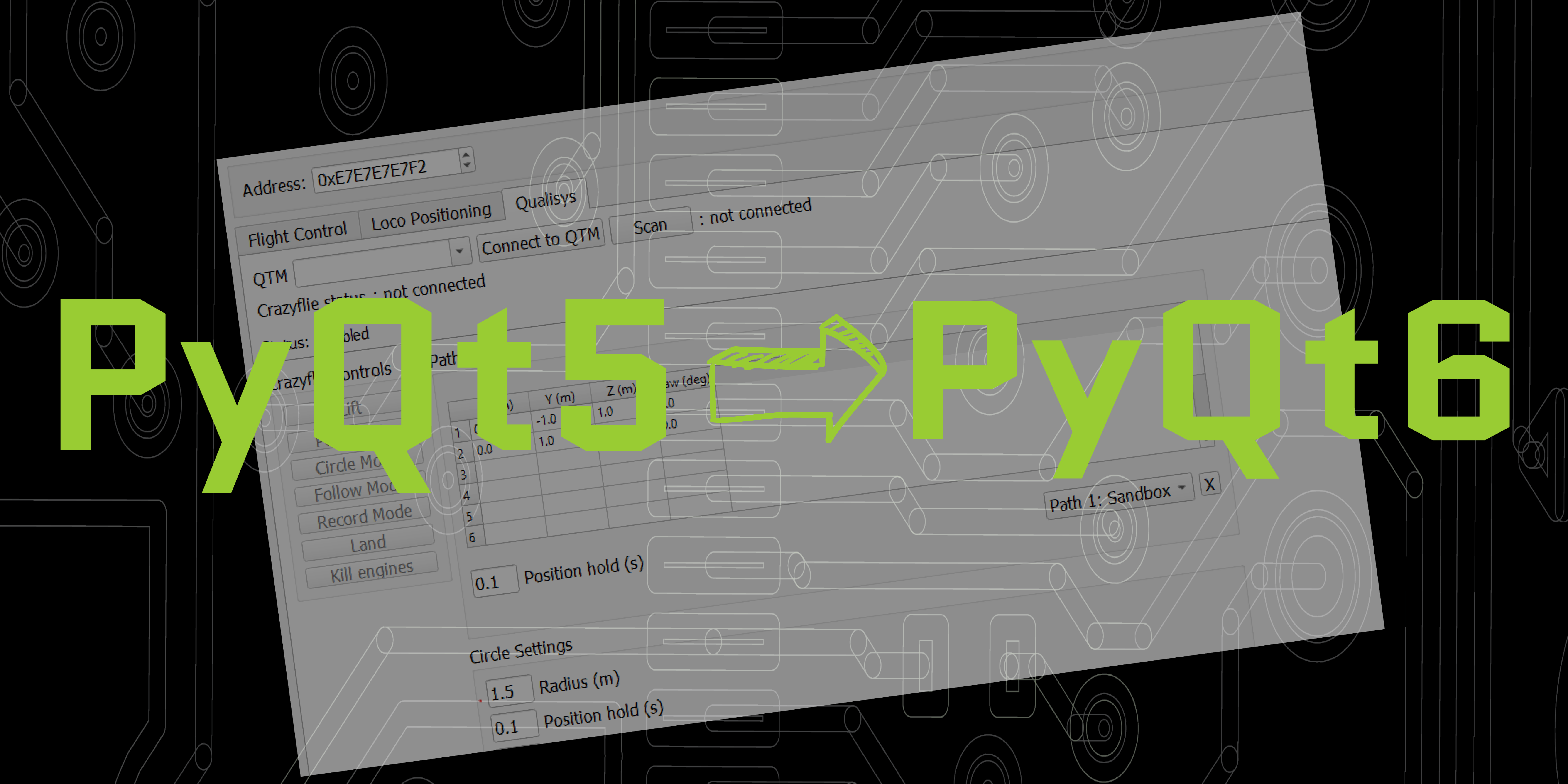
The python client is based on Qt and we have been using version 5 so far. Qt5 has been replaced by Qt6 quite some time ago and as Qt5 is not really maintained any more, we have been looking at switching to Qt6 for a long time. Finally we have taken the step, this blog post will outline what has changed.
The switch to PyQt6 is not that complicated for the majority of the client code base, apart from some minor changes in various classes, the biggest update is that enumerations are handled differently. If you check out the changes in the pull request you will see that imports have changed for obvious reasons
The main blocker for doing this change has been that the Qualisys tab was using a library that used to be available in PyQt5 but that has not been added to PyQt6, we ended up removing the Qualisys tab to be able to move on. The Qualisys tab was originally contributed by Qualisys for demo purposes and it had two nice areas of functionality that we would like to re-implement:
Motion capture positioning. It was very easy to connect a Qualisys mocap system and feed the position information to the Crazyflie for automated flight.
Trajectory support. It was possible to fly some simple trajectories, for instance a circle which is nice for testing and demos.
The idea is to re-implement the mocap connectivity using the libmotioncapture library from Crazyswarm2, as an extra bonus this would support all major mocap systems. For the trajectory part, we would like to add this as a new tab that can be used by any positioning systems, mocap, Loco, Lighthouse or flow deck. If you are interested in helping out with this, let us know!
The state of the code
The changes for PyQt6 have been merged into the master branch. It seems to work but we have not tested all functionality yet, please let us know if you run into any problems or weird behavior.
When you have pulled in the code from github you will also have to re-install all dependencies by running
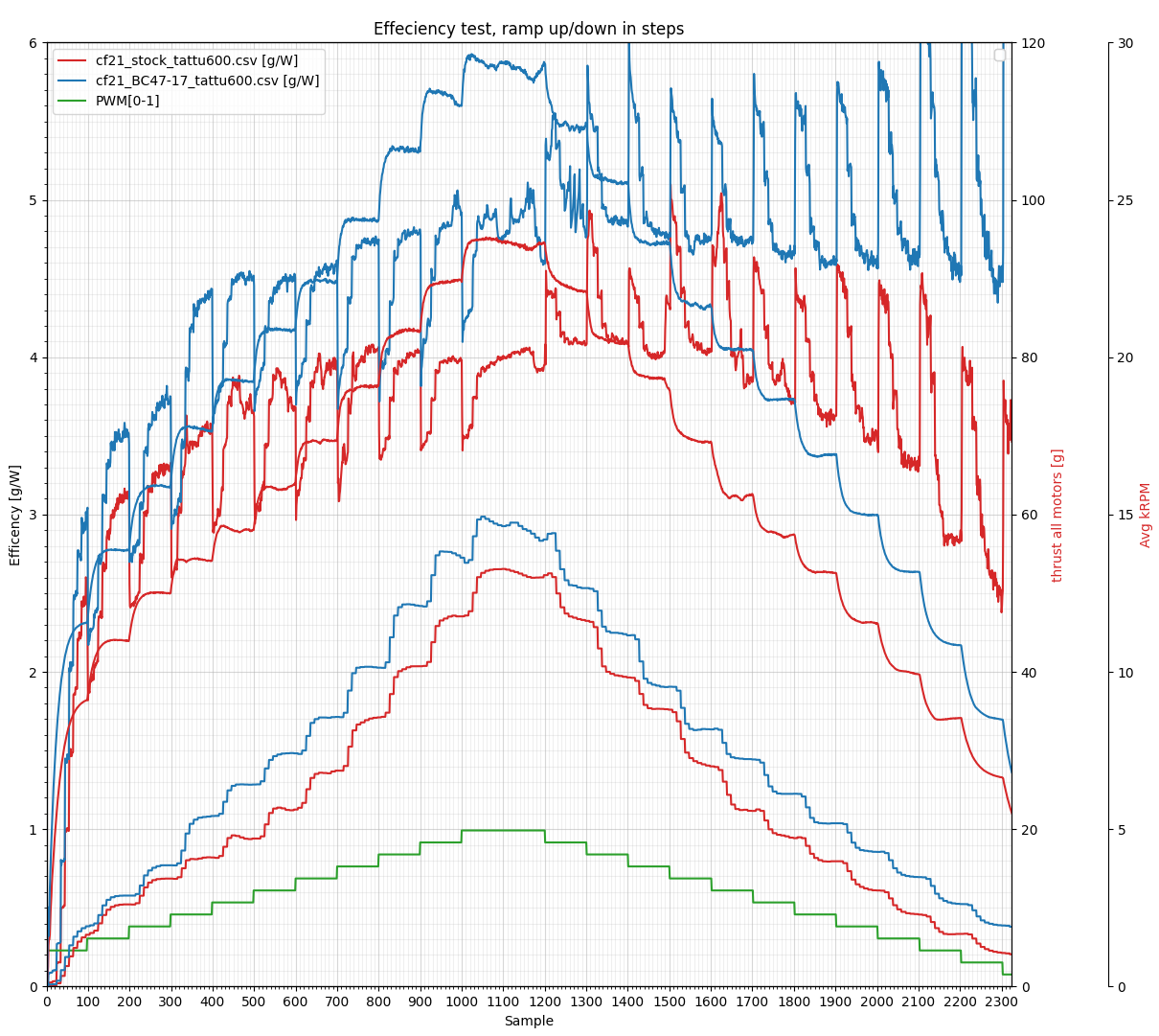
Last week our brand new 47-17 (47mm diameter, 17mm pitch) Crazyflie 2.X propeller became available in black and green in the shop! It is a custom designed propeller for the 0.8mm shaft, 7×16 coreless brushed motor, that comes with the Crazyflie 2.X. The improved design boosts the efficiency, both flight time and maximum thrust is increased with up to 15%. It is made in polycarbonate (PC) which makes it more durable so that it will withstand crashes better. The new propeller is better then the stock 45-17 in almost all areas except in noise where the new 47-17 propeller runs at a higher RPM. Below is a graph comparing the two propellers using the thrust stand we previously built. The graph is a bit messy but hopefully you can figure it out! The big takeaway is that the 45-35 propeller tops at ~4 g/W while the 47-17 tops at ~4.7 g/W using the stock 7×16 motor.
The Crazyflie 2.1 kit will continue to be shipped with the “stock” 45-35 propeller. At some point we want to switch to the new propeller in the kit. We don’t know when this will happen yet and will of course announce it here at that point :-).
After a nice (but rainy) summer, everyone is back at the office and we’re coming back to business as usual at Bitcraze. This blog post is dedicated to various bits of news, in order to get you caught up on what’s been happening during the summer.
Dev meeting theme
There were no dev meetings in August to allow everyone to rest and enjoy their vacations, but after this hiatus, we’re back in the saddle! The dev meeting will happen, as usual, on the first Wednesday of the month, so the 6th of September, at 15.00 CEST.
This month, Arnaud is going to talk about the lib: what is its current status, its architecture, and some hopes we have for the future. As usual, we’ll have a short presentation, and then a discussion; you can also join if you have more general questions or feedback. If you’re interested and willing to take part in this discussion, you can check the information on Github: https://github.com/orgs/bitcraze/discussions/884
Chargers out of stock
Some items were out of stock during the summer (like the HQ propellers) that we thankfully received soon after we came back. Unfortunately, one product is still not available: the battery charger. Since it’s part of the Swarm bundles, it also means that the bundles are out of stock too. But the wait for their restocking shouldn’t be too long, as they are scheduled to arrive around the end of next week. We’re hoping it’s not a big inconvenience for you and we thank you for your patience!
Problems with payment
We’ve noticed that some of you had some problems getting their payment through in our shop. If you’re one of the unlucky ones who faced this issue, we apologize for the inconvenience, and we want you to know we’re working with our payment provider to figure out a solution. This, unfortunately, can take some time because of the number of parties involved (there’s us, the payment provider, different banks, so the situation gets quite complex quickly). In the meantime, if you should encounter such a problem, don’t hesitate to send us an email at contact@bitcraze.se and we can help out. It would also help us to know who is facing this issue.