CrazyFlies are great for indoor applications, thanks to their maneuverability and ubiquitous character. Its small size, however, limits sensor quality and compute capability. In our recent work we present source seeking onboard a CrazyFlie by deep reinforcement learning. We show a general methodology for deploying deep neural networks on heavily constrained nano drones, using full 8-bit quantization and input scaling.
Problem definition
Source seeking can be interesting in a variety of contexts. We focus on light seeking, as seen in nature. Many insects rely on light, either for survival or navigation. Light seeking in aerial robotics has many applications, such as finding the exit out of a dark room.
Our goal is to fully autonomously find a light source, using only the onboard Micro Controller Unit (MCU) and deep reinforcement learning.
Crazyflie configuration
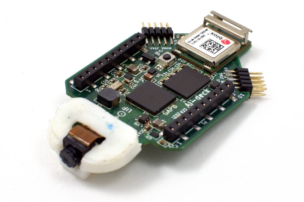
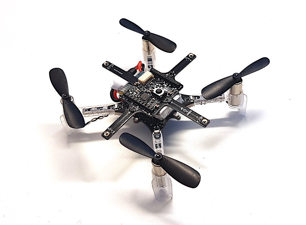
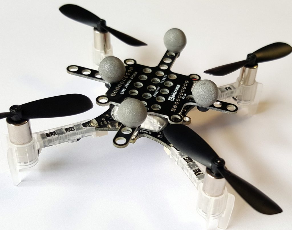
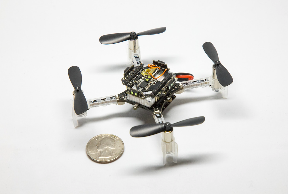
Our fully autonomous nano drone uses several standard and custom sensors. We use the multiranger and flowdeck for position control and obstacle avoidance.
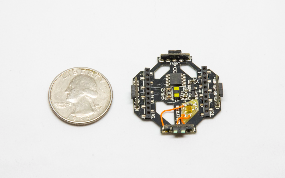
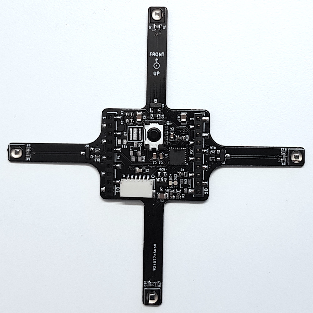
We add a custom light sensor, based on the Adafruit TSL2591 sensor. The custom light sensor nicely fits in the multiranger deck, adding little mass and inertia (total vehicle mass is 33 grams).
Algorithm
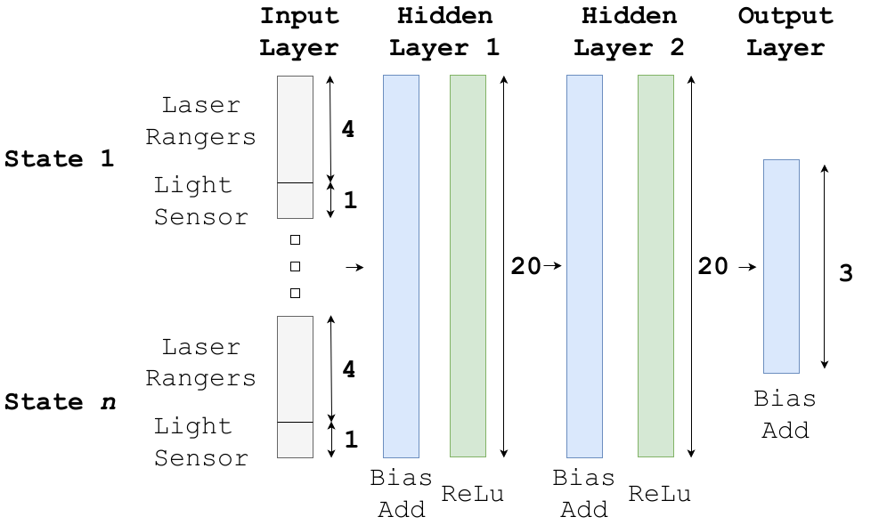
We use a deep reinforcement learning algorithm with a discrete action space. The neural network policy has laser rangers and light readings (current and past values) as input. The neural network tells the drone to rotate left, right or fly forward. We train a neural network with 2 hidden layers of both 20 nodes, featuring bias add and relu activation functions. The input layer is a vector with a length of 20 (4 states), which, compared to images, greatly reduces computational effort.
Simulation and conversion
We train our agent in simulation using the Air Learning simulation platform, after which we fully quantize the neural network to 8-bit integers.
To maintain accuracy after quantization, we have come up with quantization innovations. Both input layer and all tensors in the network need to have a pre-defined [min,max] range in float32, to convert to 8-bit integers.
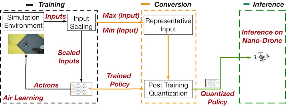
In the input layer, not all inputs have the same range. That is, a laser ranger can have values from 0 to 5 meters while our light sensor may return a value between 0 and 300 lux. To avoid this issue, we scale all inputs to the same range.
Additionally, the tensors in the network need to have an assigned [min,max] range for quantization. To achieve this, we input a range of representative input into the unquantized model, and read out the values of intermediate layers. With this strategy, we arrive at a 2.9x speed-up compared to float32 inference.
Implementation
We use Tensorflow Lite to deploy our tensorflow models in C on the CrazyFlie. The TFMicro Stack, together with the actual model, almost completely fill up the available RAM.
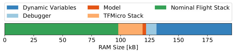
The total amount of RAM available on the CrazyFlie 2.1 is 196kB, of which only 131kB is available for static allocation at compile time. The Bitcraze software stack uses 98kB of RAM, leaving only 33kB available for our purposes. The TFMicro stack takes up 24kB, thus leaving 9kB for the actual model (e.g., weights, bias terms).
We also analyzed CPU usage, and noticed a high amount of interrupts by the ‘stabilizer’ thread, i.e., the PID controllers. Because of these interrupts, inference of our model takes 46.4 times longer than it would have been without interruption.
Our quantized model is 3kB. If it were an FP32 model, it would have taken 12kB, which would not have fitted in the available memory. We were able to run inference at 4Hz, compared to the estimated 1.4Hz of the same but unquantized model.
In a practical sense, we noticed a decreased level of stability when increasing model size. Occasionally the drone would reboot randomly while flying. Possible causes for this behavior are RAM overflow and task scheduling problems in RTOS. Besides, we observed variation in performance loss after quantization. Some of our trained models would just keep rotating after quantization, while our final model demonstrates robust source seeking behavior. This degree of uncertainty can possibly be avoided using quantization aware training.
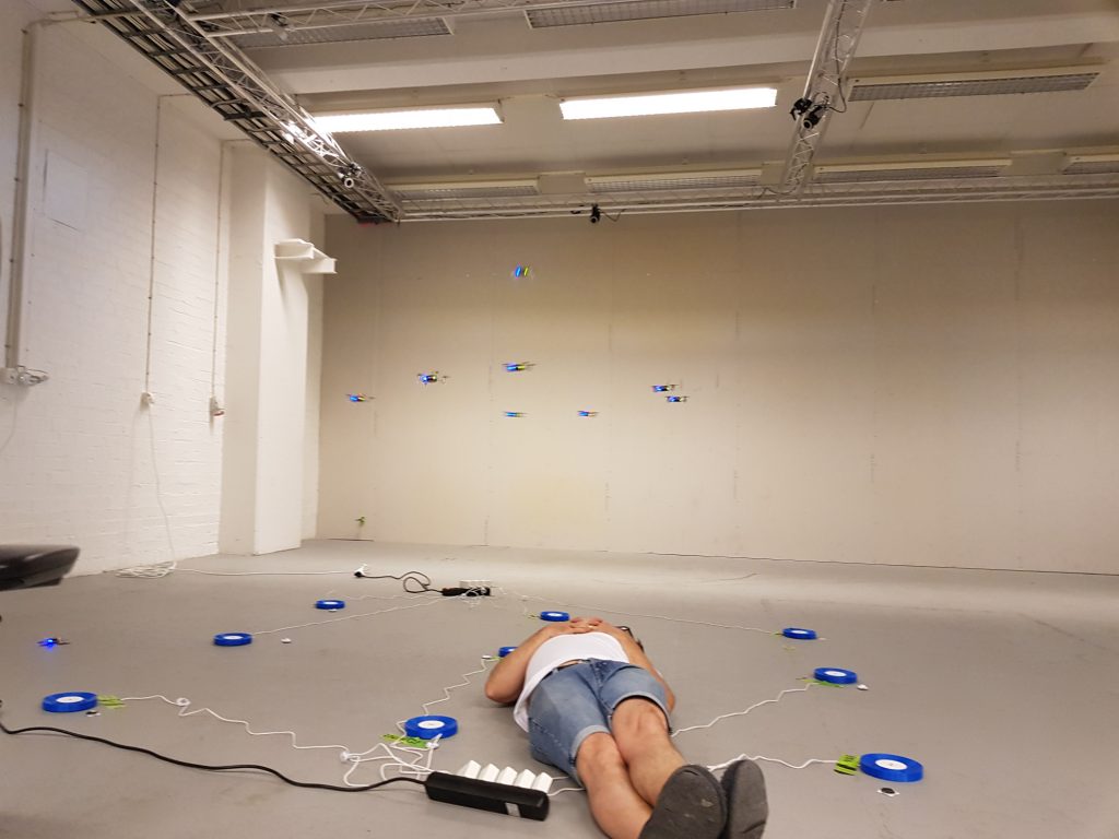
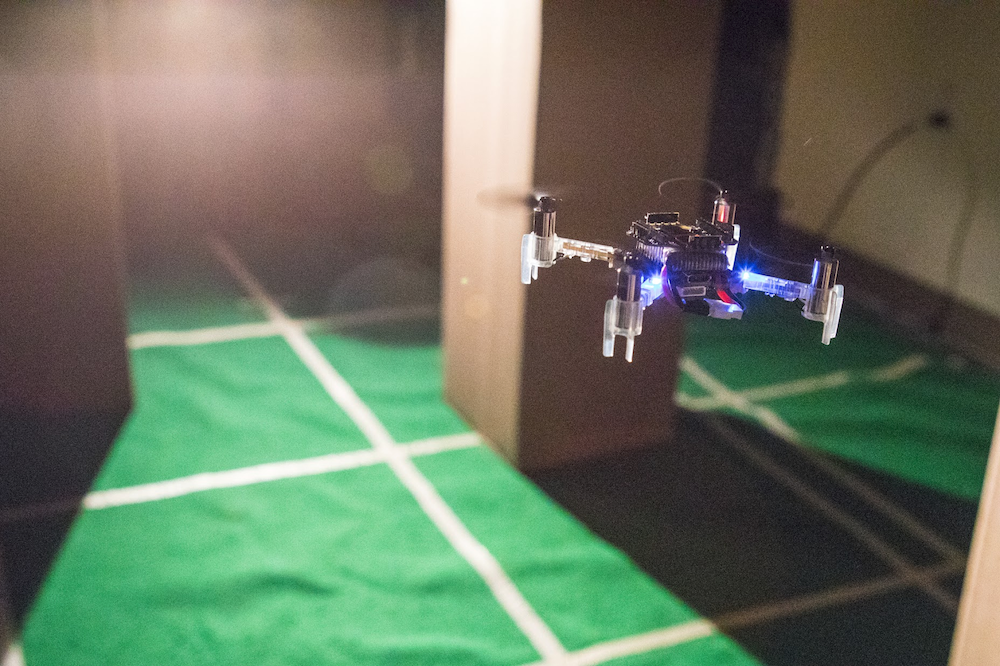
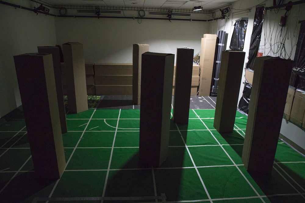
Finally, flying in a dark room without a position estimate can be challenging. The PID controllers heavily rely on information provided by the Flow Deck. This information is limited when little light is present while flying over a floor containing little features. To fix this, we added mats with texture on the ground, adding features and enabling stable flight in a dark room.
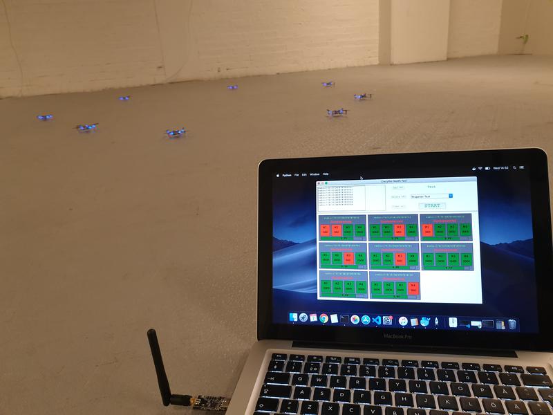
Flight tests
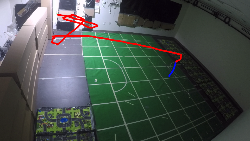
To validate our results in simulation, we created a cluttered environment with a light source. We randomly initialized the drone in the room, and hereby observed a success rate of 80% in a total of 105 flight tests. By varying the environment and initial drone position, we learned more about the inner workings of our algorithm.
We learned that the algorithm performs better with more obstacles, and that a closer initial position improves performance. Generally, source seeking far away from the source seems really hard. Almost no variation in source strength exists between different measurements, and the drone observes mostly noise.
Outlook
With our methodology, we were able to perform fully autonomous source seeking using deep reinforcement learning on a Cortex-M4 MCU. We hope our methodology will be applicable to other TinyML applications where resources are heavily constrained. Developing custom accelerators for a specific workload is time-consuming and expensive, while general purpose MCU’s are cheap and widely available. With our methodology, we unlock new applications for learning algorithms on heavily constrained platforms.
Links
Video: https://www.youtube.com/watch?v=wmVKbX7MOnU
Paper: https://arxiv.org/abs/1909.11236
Github: https://github.com/harvard-edge/source-seeking
Feel free to contact us might you have any questions or ideas: bduisterhof@g.harvard.edu