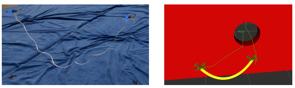
As the Crazyflie ecosystem expands, more and more novel aerial (but also ground or hybrid) robots are being built with one of the Crazyflie controllers onboard. For recent examples, you can check e.g. the recent blogpost about ICRA 2022.
In this post, I will introduce yet another Crazyflie-Bolt-powered aerial robot, the Flapper Nimble+ from our company Flapper Drones, which unlike other flying robots doesn’t have any propellers but uses flapping wings instead.
The best aerial robot design is…
Small drones, or micro air vehicles, have seen a lot of progress and new developments in the last 20 years. The most widespread design nowadays is a quadcopter, such as the Crazyflie 2.1. But is a quadcopter the ultimate (micro) drone solution? At Flapper Drones, we believe nature might provide even better designs… For some applications at least! 😊
Flying like a bird…
Flapper Drones is a spinoff of the MAVLab of the Delft University of Technology. At the MAVLab, we have been researching bio-inspired flight as part of the DelFly project since 2005. From the beginning, the goal has been to develop a lightweight, mission capable micro air vehicle, the design of which would draw inspiration from nature. Over the years, many such MAV concepts have been designed, built and tested, including the DelFly Micro, the world’s smallest camera-equipped MAV, or the DelFly Explorer, the first autonomous flapping-wing MAV equipped with a stereovision system. All these designs were propelled by a pair of flapping wings, while being controlled (and passively stabilized) by a tail such as birds or men-made airplanes.
… or an insect
The latest design, the DelFly Nimble is insect-inspired instead. What does that mean? The Nimble has no tail, which would provide the damping needed for stable flight. Instead, it is stabilized actively, by adjustments of the motion of its flapping wings. This is what all flying insects and also hummingbirds do. Flies, for example, sense their body motions with their halteres, drum-stick like biological gyroscopes, and adapt their wing motion accordingly to stay balanced…. or to be agile, when someone is trying to swat them!
And while the Nimble was originally built just to demonstrate that an insect-inspired flying robot can be built, eventually we could also use it to learn more about the flight of insects:
Flapper Drones – how do they work?
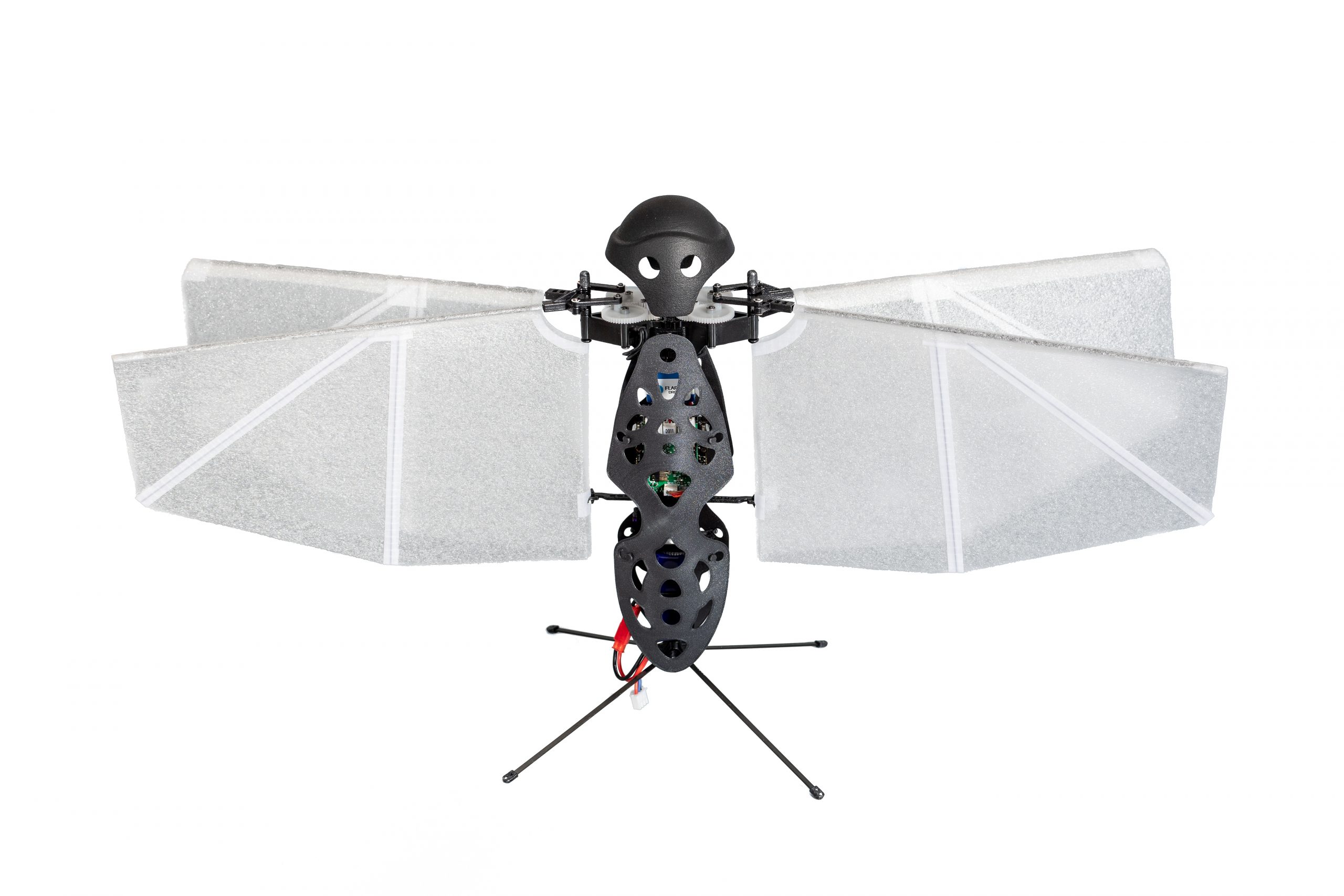
The Flapper Nimble+ is the commercial (and enlarged) version of the DelFly Nimble, developed and produced by Flapper Drones. To our knowledge, it is the first, and so far the only hover-capable tailless flapping-wing drone available!
The thrust keeping the Nimble+ airborne is created by its four flapping wings, which flap back and forth horizontally, about 10 to 12 times per second.
The wing actuation mechanism allows to adjust the flapping frequency of the left and right wing pairs independently, which enables control of the roll rotation. Pitch rotation is controlled by adjusting the mean wing position within the stroke plane, which shifts the mean thrust force forward or backward with respect to the center of mass, and also introduces a stabilizing dihedral angle in forward flight. Finally, yawing motion is achieved by tilting the wing roots of the left and right wing pair asymmetrically:
Advantages of flapping wings
The use of flapping-wing drones such as the Flapper Nimble+ brings several advantages. Next to their attractive biological appearance, the soft flapping wings produce less intrusive, low frequency sound and are safer, compared to propellers. As the wings move back and forth, minor mid-air collisions are not a problem. The wings bounce off objects leaving no damage, and the drone keeps flying as this only represents a minor disturbance:
The aerial drag characteristic is also different and helps with precise indoor flight. As soon as zero attitude is commanded, the Nimble+ goes into halt in a matter of several wingbeats, making it an ideal choice for novice drone pilots as well as in constrained or cluttered indoor spaces. Finally, the flapping wings can provide additional lift force as they also glide in forward flight. This can improve the power efficiency by over 20%, compared to hovering.
Otherwise, Flapper Drones can be operated as any other drone, with vertical take offs and landings, quick maneuvers and flight in any direction:
Crazyflie Bolt & compatibility
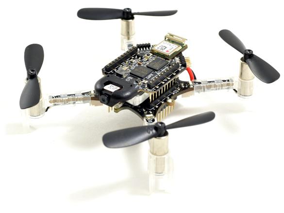
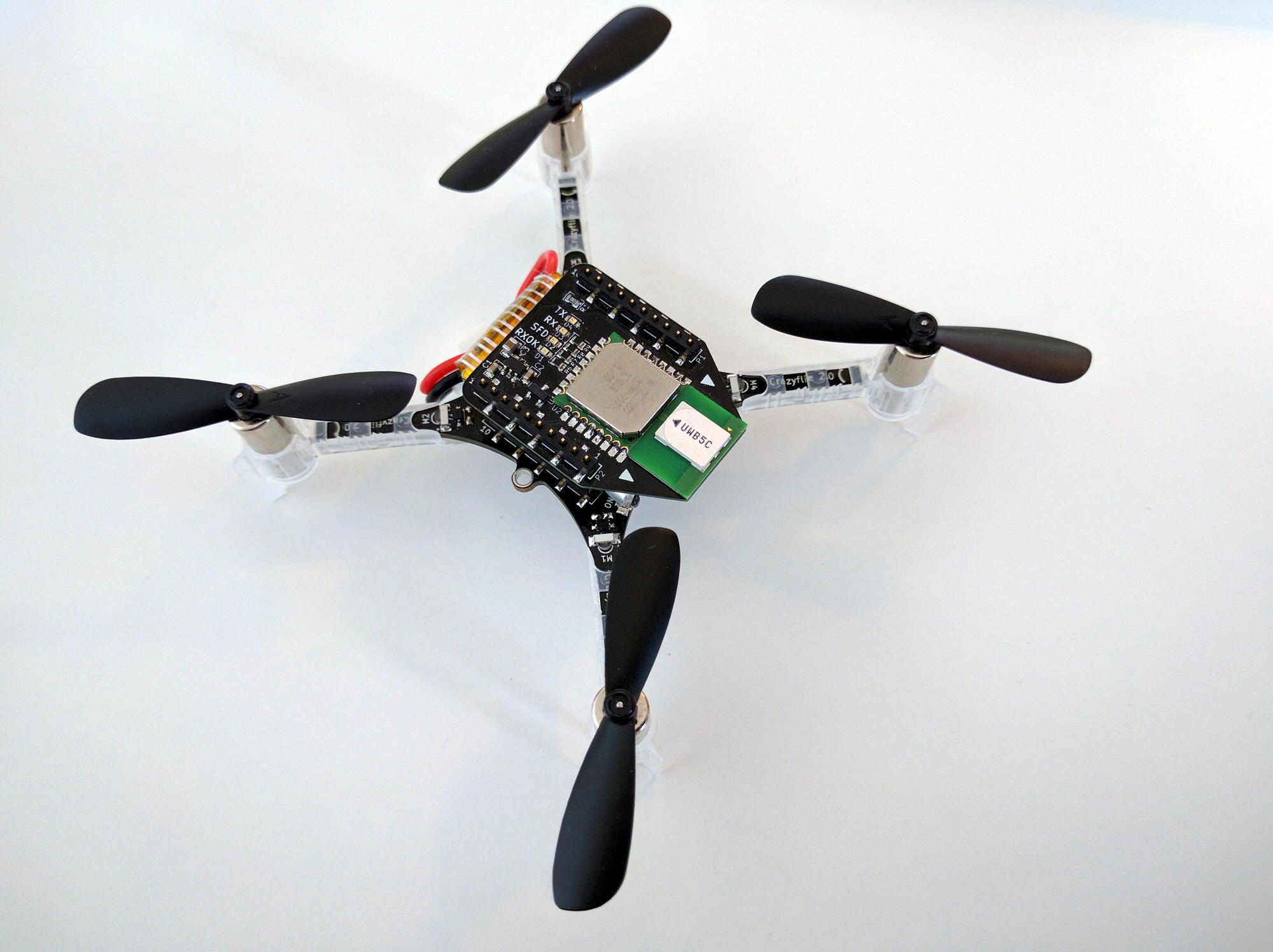
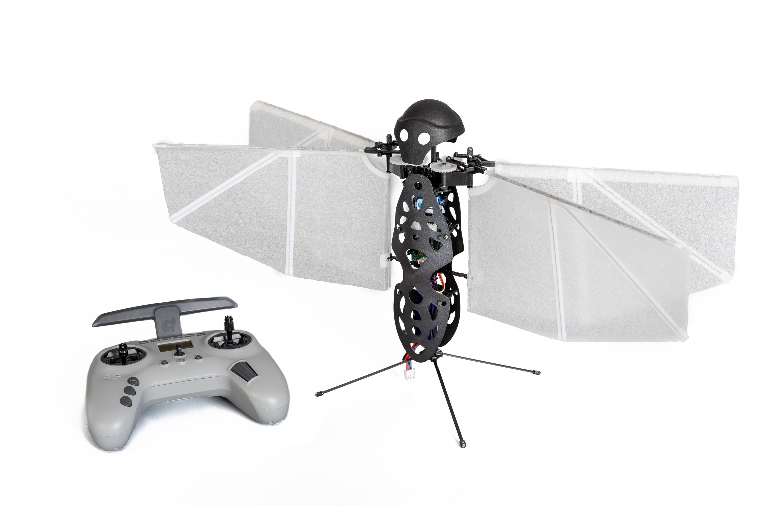
The Flapper Nimble+ is powered by the Crazyflie Bolt 1.1, where the Bolt’s BMI088 IMU and STM32F4 MCU are suitable substitutes to the halteres and brains of the real fly. We made this choice, because this enables compatibility with most of the Crazyflie ecosystem, but also, because we felt the only way a Crazyflie would do justice to its name is if it had flapping wings😊
Currently, the Nimble+ uses a fork of the Crazyflie firmware, which is of course open source. Moreover, with the recently introduced platform functionality, we will be able to include the Flapper platform into the official crazyflie firmware very soon (expected still in July 2022). This means that the Flapper remains compatible with the official Python libraries, the PC client or the smartphone app. But also third-party projects like the Crazyswarm or the Skybrush should only require minor adjustments, if any, to operate a swarm of Flappers. Thus, for the existing Crazyflie users, switching from a Crazyflie to the Flapper should be a breeze!
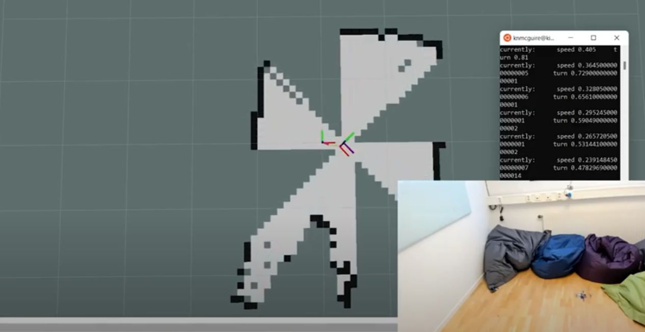
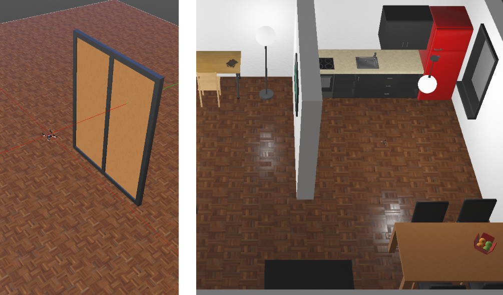
The Flapper Nimble+ is hardware compatible with most of the Crazyflie expansion decks. While software support remains experimental (the Flapper Nimble+ is not a native Crazyflie product, after all), many of the decks work out of the box and others might need just minor firmware modifications. Would you like to fly the Nimble+ autonomously? Add an LPS or Lighthouse deck and you’re good to go!
For more details regarding deck compatibility, you can check this overview.
Applications
While the Nimble+ was originally designed for drone shows and similar entertainment applications, the open-source firmware and expansion decks enabling autonomous flight make it ideal also as for academic research and, in general, as a development platform. Are you researching swarming, and would you like to make your swarm even more bio-inspired? Are you developing new sensors, or new controllers (possibly even bioinspired), which you would like to test on a new type of flying platform? Are you interested in the aerodynamics of flapping wings, or the flight dynamics of insect-like flight? Or are you just curious and would you like to learn more about bioinspired flight? In all these cases, a Flapper might be what you are looking for!
The 114-g and 49-cm wide Flapper Nimble+ has been designed as a modular system where any part can easily be replaced. Flapper Drones provides all the spares, which are available upon request. If you are interested in using the Nimble+ for entertainment, rather than research, you can modify the appearance by creating your own body shells, which can also be illuminated by RGB Leds (a suitable interface and power supply is already integrated). Or even by altering the design of the wings. Finally, you can easily extend the Flapper with your own sensors, or other devices. Would you like to add a tail? A gripper? A perching device? This is all possible, as long as these additions fit within the payload limit of about 25 grams.
Available soon in the webstore!
Did you get (bio)inspired, and would you like to try an insect-like flying robot yourself? Then we have some good news! The Flapper Nimble+ will soon be available for sale in an exclusive partnership with Bitcraze and their webstore. Checkout the product description and leave your email address behind, such that you get a notification when the Flappers are in stock and ready to ship. The first batch of 10 units is expected to be available at the end of summer, so do not wait too long 😉
Want to learn more?
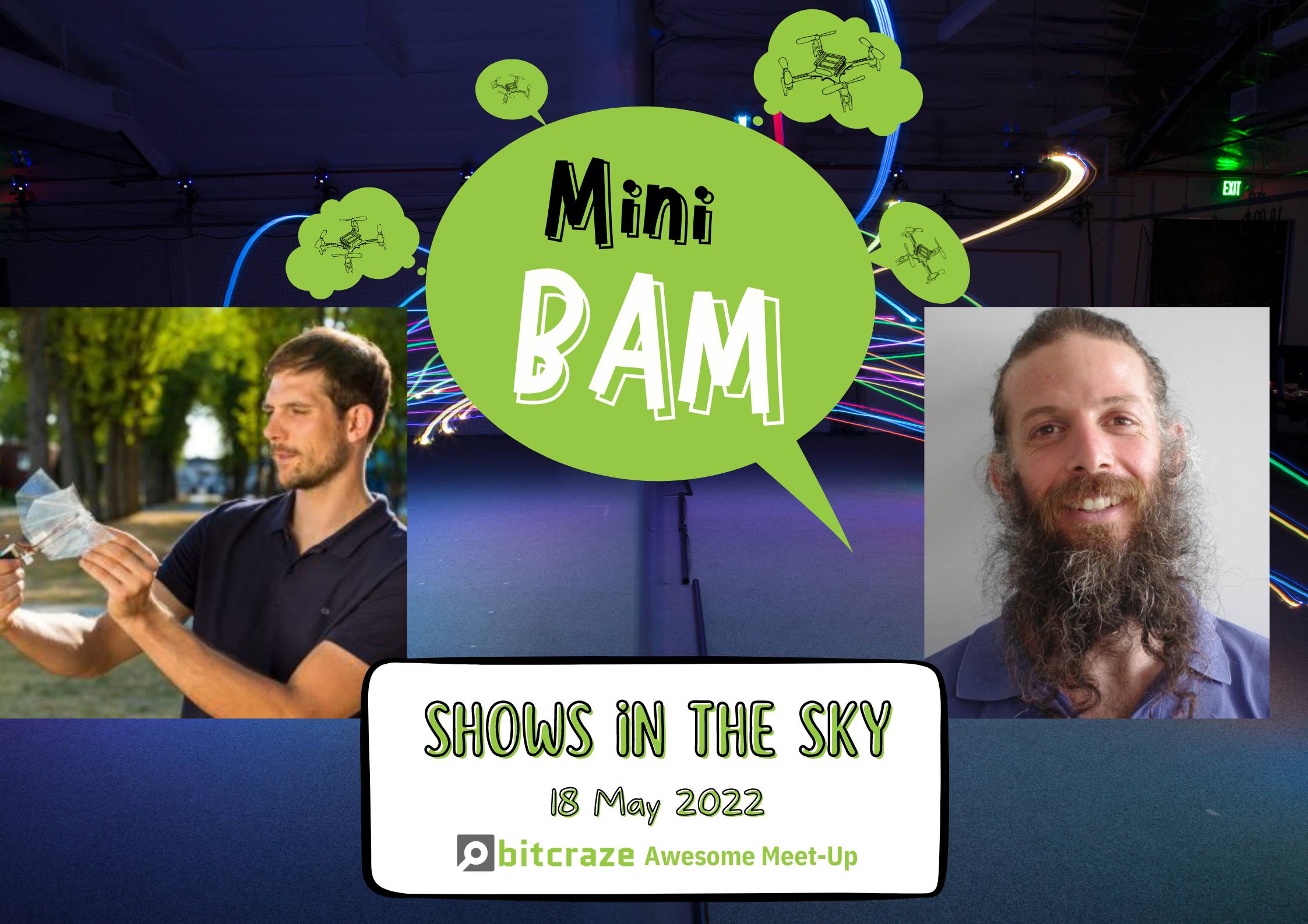
To learn more about Flapper Drones, you can check our website, or watch the talk I gave at the last miniBAM: