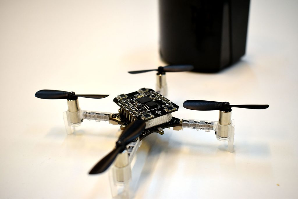
We are happy to announce that we have gotten Crazyflie 2 to fly autonomously using the Lighthouse deck and Lighthouse V2 base-stations. This was a very requested features, and while this is not stable and ready to use yet, it is a great milestone toward Lighthouse V2 support.
There exists two incompatible versions of the Lighthouse positioning system. Version 1 was released with the original HTC Vive VR system. In this system base-station are using two rotating laser beam that sweeps the room, one horizontal and one vertical, and an omnidirectional synchronization flash to allow IR light receiver to be located in the room. One limitation of this version is that up to two base-station can be used and no more, this is mainly due to the fact that beam identification is done using a TDMA scheme: base stations switch-on their laser in a dedicated time-slot one after each-other and adding more time slots for more base-stations will greatly reduce the update rate of the system.
Lighthouse V2, was released with the HTC Vive PRO headset and is also used by the Valve Index. The big change is that laser sweeps now carries modulated data and that there is only one rotor with two angled slit instead of the two rotors for V1. The V2 sweep data is described as ‘Sync on beam’ and contains timing information of how long it has been since the synchronization event (ie. when the rotor crossed 0 degree). The sweep data also allows to identify the base-station that has transmitted the sweep. This removes the need for an omni-directional synchronization pulse and allows more than two base-station to operate at the same time in the same space, since their sweeps can now be identified and timed.
The lighthouse V2 system is very elegant and scalable. However, actually decoding the signal from the sweeps has taken a lot of time since it is not documented and we needed to find-out what the encoding actually was. There has been effort on the internet to understand how the system worked, the most useful one is this github ticket that goes from raw data acquisition to fully unlocking the beam encoding.
I have been working on-and-off for a long time on making an FPGA design for the lighthouse deck to acquire and decode Lighthouse V2. The main blocking point until now was that I had not been able to reliably acquire useful signal from the system in order to allow real-time decoding on the Crazyflie. Added to that, there was some inconsistency between what we though the system was doing and what we could gather from the base-stations debug console. Recently though, the last piece of the puzzle, was to discover that the beam encoding was not Manchester, as we though, but Bi-phase mark code FM1 (BMC). Once this decoding was used everything made sense and worked.
Added to that, I started using SpinalHDL instead of raw Verilog to write the FPGA design which allows for much quicker iteration, much less frustration, and it also allowed me to easily make the design multi-clock which is required to decode the BMC signal: the beam decoder runs at 48MHz, and the rest of the system works at 24MHz. This design is required since the FPGA we use in the lighthouse deck is not fast enough to run everything at 48MHz.
The result, is a new FPGA firmware for the lighthouse deck that receives, identify and decode Lighthouse V2 sweep signal and send them over to the Crazyflie. The Crazyflie still has a little pulse packing to do (putting together pulses from a single sweep received on multiple sensors) and then can use pulse timing information to calculate azimuth and elevation at which the base-station sees the Crazyflie. This information is the same as the one we get from Lighthouse V1 and so the same algorithm can be used to calculate the Crazyflie position.
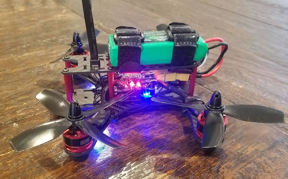
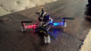
I hacked a proof of concept was this last fun Friday and it flies!
If anyone is curious the code for this demo has been uploaded as an out-of-tree driver and the code for the FPGA parts is already in the lighthouse-fpga project. The current Crazyflie code is too incomplete to be usable, but it is a nice starting point if anyone wants to play with Lighthouse V2 and the Crazyflie right away ;-).
As a side note, the Bitcraze team will shrink temporary as I, Arnaud, will go in parental leave until mid-August. I look forward to this new adventure and I trust the lighthouse V2 development and the forum will be in good hands in my absence.