We have worked hard last week to get a new fresh release out before the summer months are on our doorstep. Not only that we would like to make sure that important bugs are fixed before some of us go on our holiday, but also to be able to display our new AI deck features! Here is an overview of what has been changed
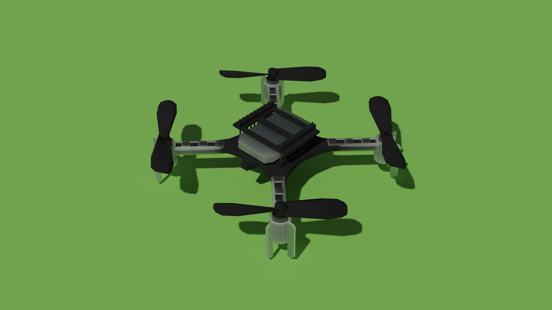
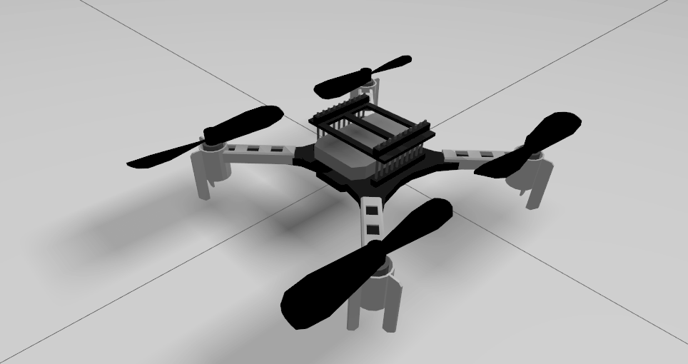
AI deck over air flashing
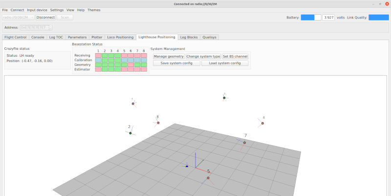
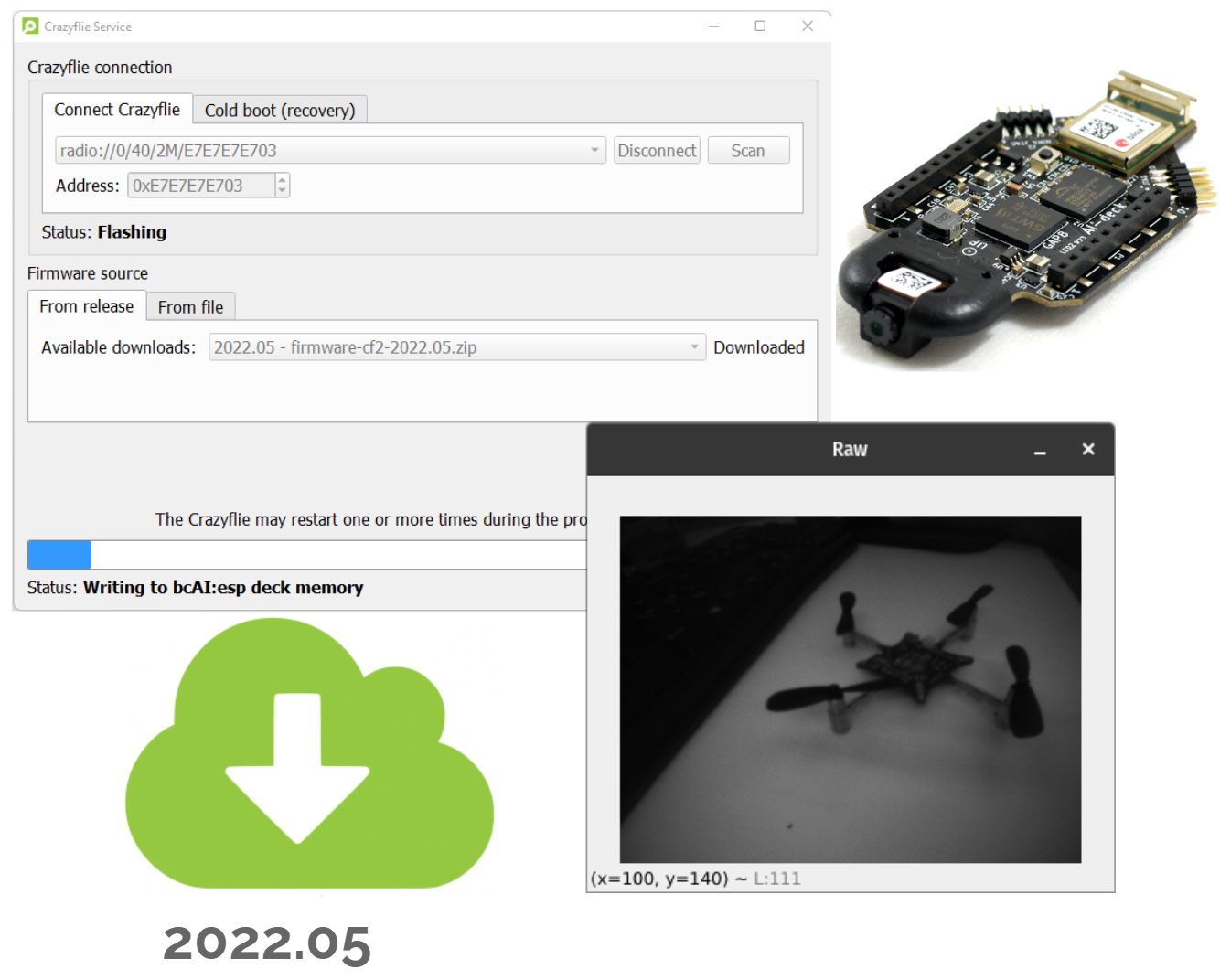
As you can probably see in the release notes of both the python libraries and the firmware, most of our changes are focused on making it possible to develop for the AI deck without using a programmer all the time. If the STM and NRF firmware of the Crazyflie is fully updated, and the ESP firmware on the AI deck, it should now be possible to flash an AI deck example binary with a Crazyradio! For older versions of the AI deck 1.X (Rev A to C) it is unfortunately still necessary to use the JTAG programmer one last time to flash a bootloader on the GAP8, but after that it should not be needed anymore.
Please check out the new update AI deck tutorial for setting up the AI deck for this new functionality.
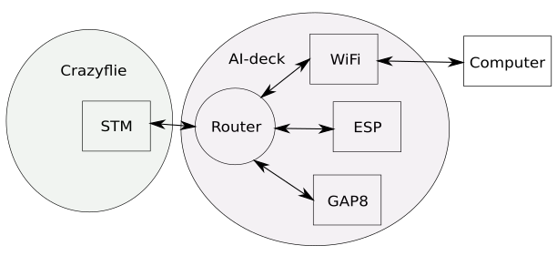
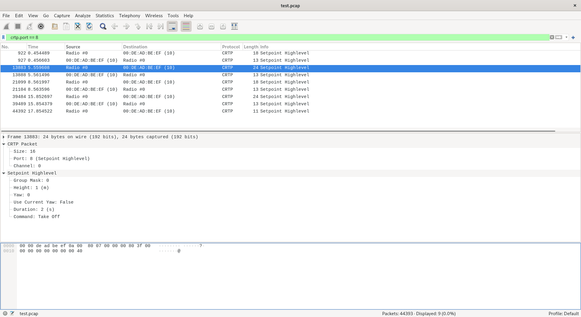
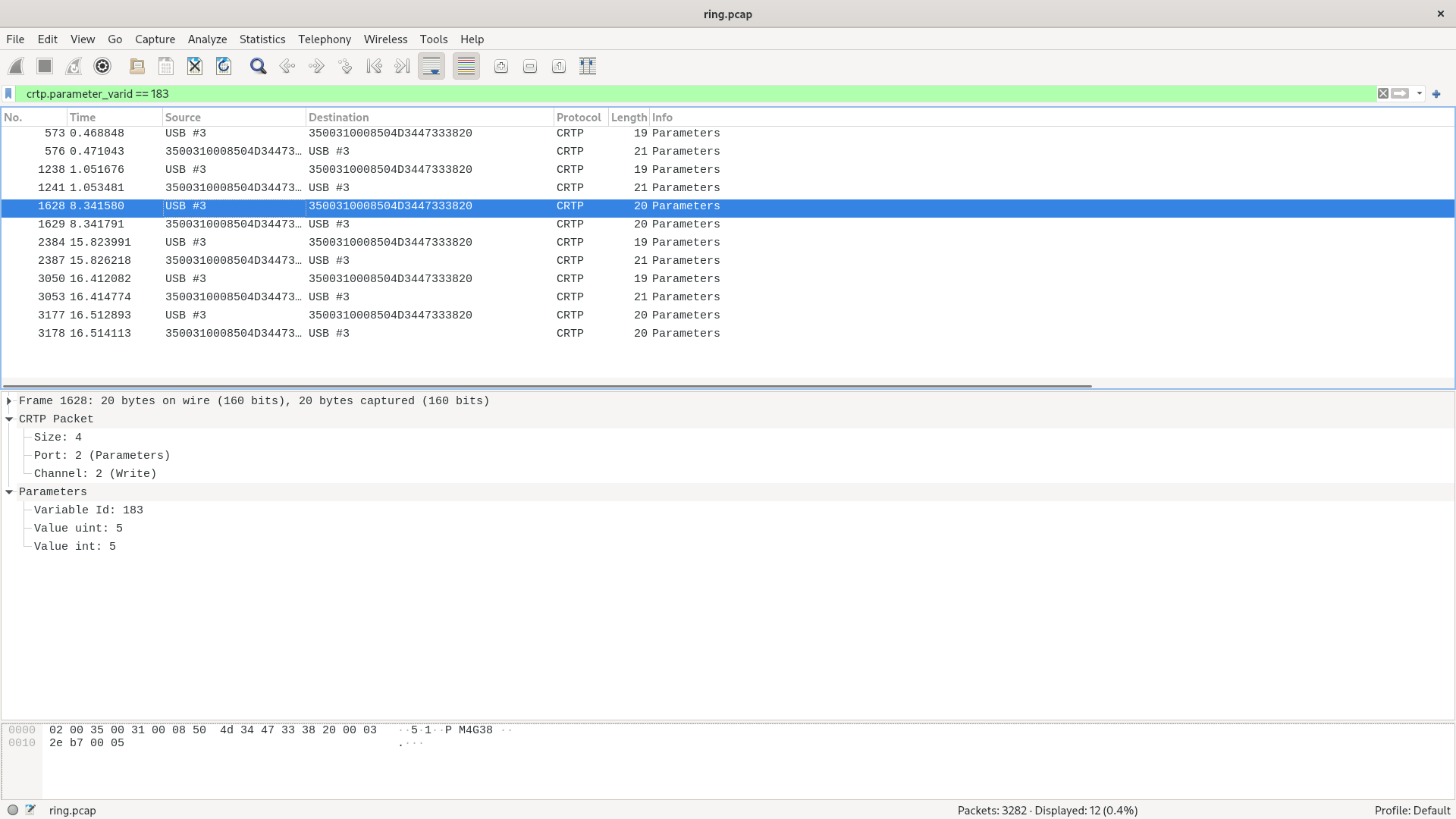
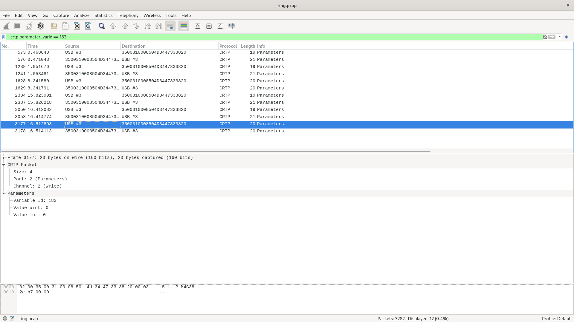
Crazyflie Packet eXchange (CPX)
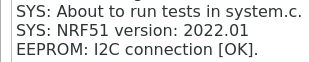
In the light of the work we have done for the AI deck, we also have started to implement a new, inter MCU protocol called the Crazyflie Packet Exchange. Since with the AI deck, we are adding 2 additional microprocessors to the Crazyflie architecture, it was crucial to handle the communication between all platforms and communication channels properly. Currently the functionality is mostly enabled to tailor Wifi streaming and console printouts for the AI deck, but it is meant to be a generic protocol which in the future, should be able to handle more combinations like for instance, command messages through wifi?
You can read about CPX in the crazyflie-firmware repository doc and we will be writing a more detailed blogpost about this later.
Controller Python bindings
For the last part of the Grand tour trip, we had a hackathon with the IMRC lab of TU Berlin and our close collaborator Wolfgang Hönig, in which we managed to convert the PID controller, Mellinger controller and the motor mixing into python bindings, which can be used in the experimental simulator of the Crazyflie.
There is no Pypi release of these, you will need to pull the latest crazyflie-firmware repo and build the bindings with ‘make bindings_python’
Additional fixes
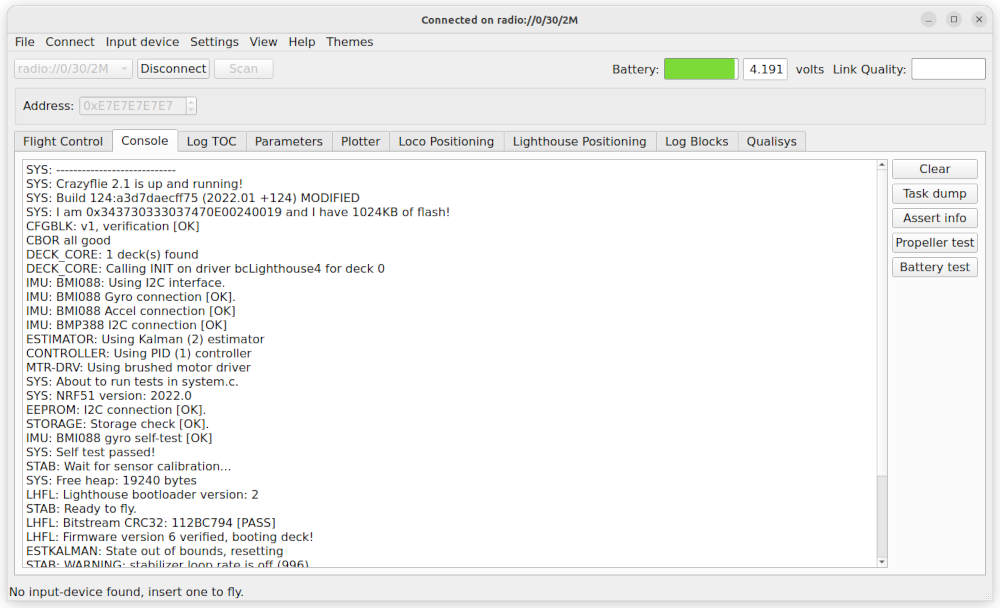
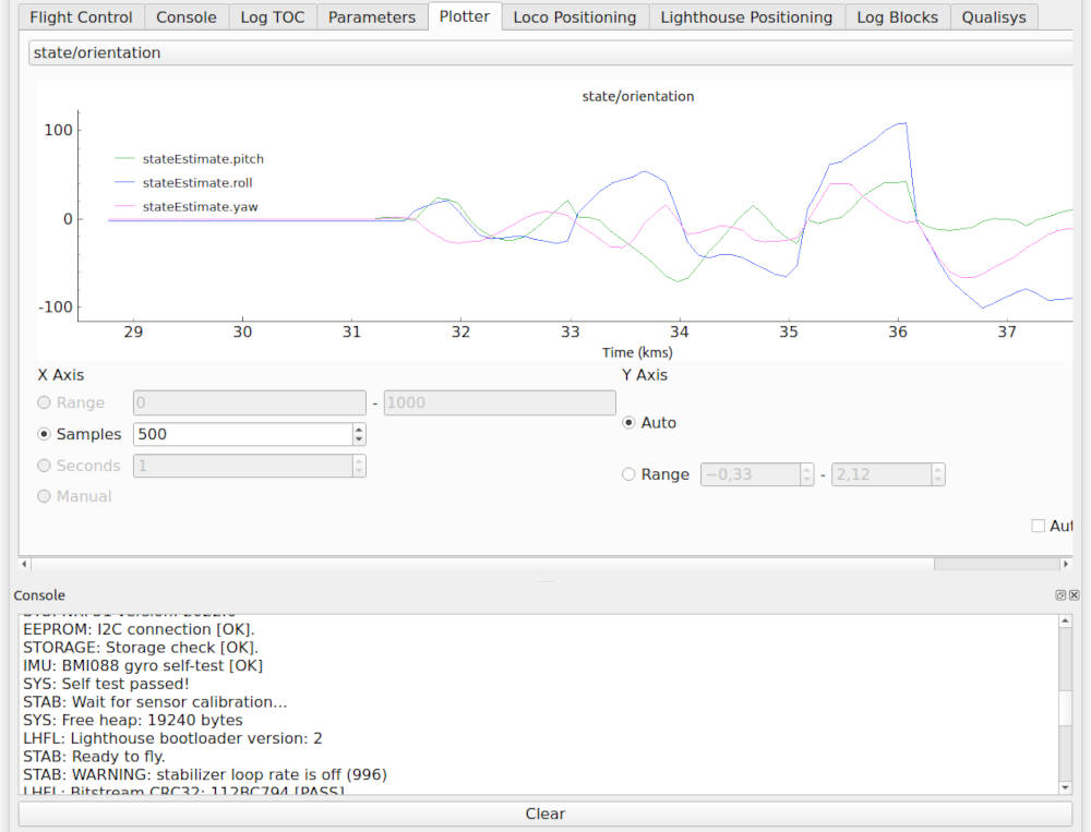
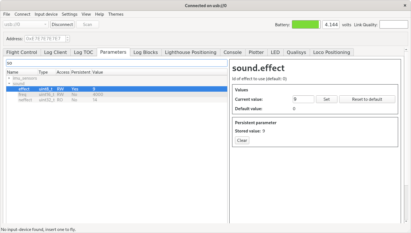
We have some additional fixes to both the python libraries and firmware. For the STM we have updated the STD peripheral library and solved several build issues. For the cfclient, we fixed a lot of issues that were caused by either the latest version of python, as it was more stricter with type definitions, and some issues QT. Moreover, the LED ring headlight functionality has been restored, and the cfbridge.py script, used for the PX4 crazyflie 2.1 tutorial, is re-added, since it suddenly disappeared a few releases ago.
Update and Feedback
Make sure to update your cfclient with ‘pip install cfclient –upgrade’ and to reflash the new stable firmware. For AI deck users, try out our our new tutorial to try out both CPX, the over air flashing and the wifi example. The new AI deck functionalities has been subjected to some limited testing so if there is anything wrong or unclear, please let us know in the forum! The feedback will help the AI deck to become a more stable product for development, so we would be very grateful if you would be able to help out with that.