This week we have a guest blog post from Dr Feng Shan at School of Computer Science and Engineering
Southeast University, China. Enjoy!
It is possible to utilize tens and thousands of Crazyflies to form a swarm to complete complicated cooperative tasks, such as searching and mapping. These Crazyflies are in short distance to each other and may move dynamically, so we study the dynamic and dense swarms. The ultra-wideband (UWB) technology is proposed to serve as the fundamental technique for both networking and localization, because UWB is so time sensitive that an accurate distance can be calculated using the transmission and receive timestamps of data packets. We have therefore designed a UWB Swarm Ranging Protocol with key features: simple yet efficient, adaptive and robust, scalable and supportive. It is implemented on Crazyflie 2.1 with onboard UWB wireless transceiver chips DW1000.
The Basic Idea
The basic idea of the swarm ranging protocol was inspired by Double Sided-Two Way Ranging (DS-TWR), as shown below.
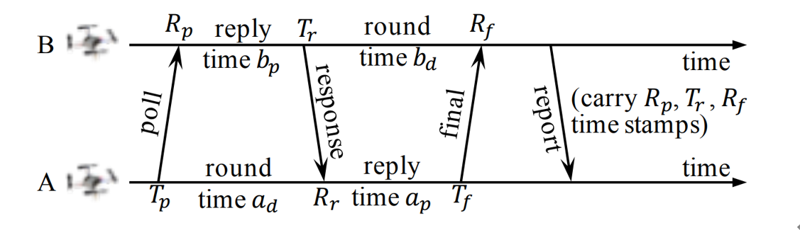
There are four types of message in DS-TWR, i.e., poll, response, final and report message, exchanging between the two sides, A and B. We define their transmission and receive timestamps are Tp, Rp, Tr, Rr, Tf, and Rf, respectively. We define the reply and round time duration for the two sides as follows.

Let tp be the time of flight (ToF), namely radio signal propagation time. ToF can be calculated as Eq. (2).

Then, the distance can be estimated by the ToF.
In our proposed Swarm Ranging Protocol, instead of four types of messages, we use only one type of message, which we call the ranging message.
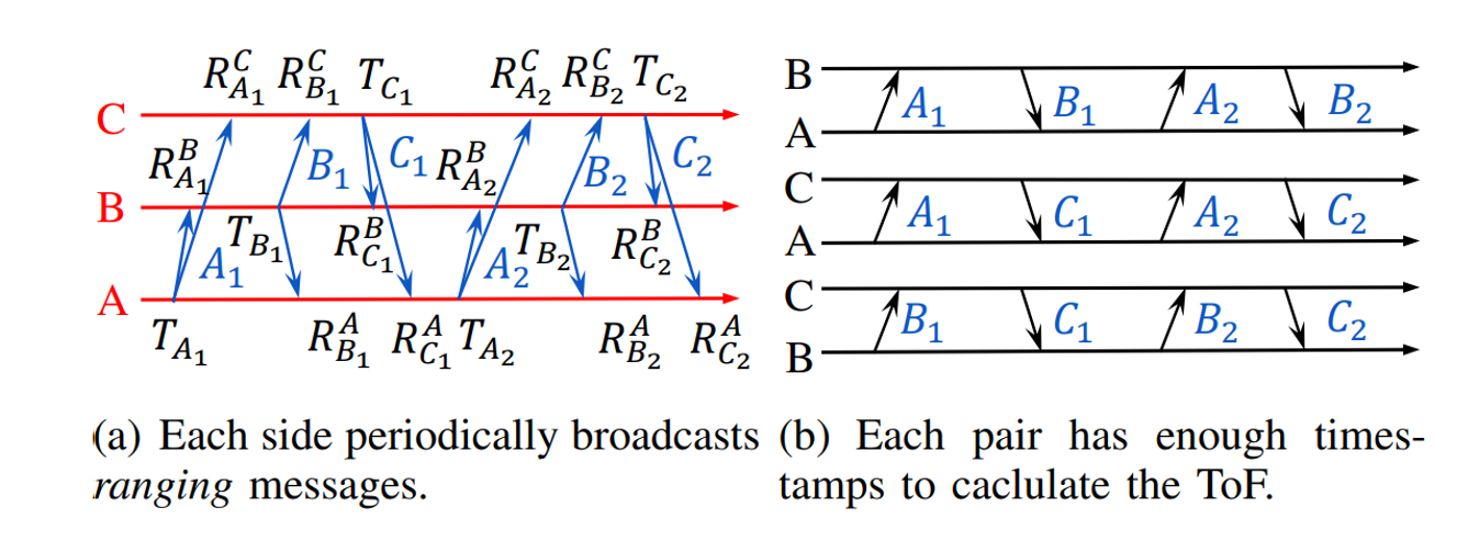
Three sides A, B and C take turns to transmit six messages, namely A1, B1, C1, A2, B2, and C2. Each message can be received by the other two sides because of the broadcast nature of wireless communication. Then every message generates three timestamps, i.e., one transmission and two receive timestamps, as shown in Fig.3(a). We can see that each pair has two rounds of message exchange as shown in Fig.3(b). Hence, there are sufficient timestamps to calculate the ToF for each pair, that means all three pairs can be ranged with each side transmitting only two messages. This observation inspires us to design our ranging protocol.
Protocol Design
The formal definition of the i-th ranging message that broadcasted by Crazyflie X is as follows.
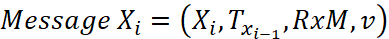
Xi is the message identification, e.g., sender and sequence number; Txi-1 is the transmission timestamp of Xi-1, i.e., the last sent message; RxM is the set of receive timestamps and their message identification, e.g., RxM = {(A2, RA2), (B2, RB2)}; v is the velocity of X when it generates message Xi.
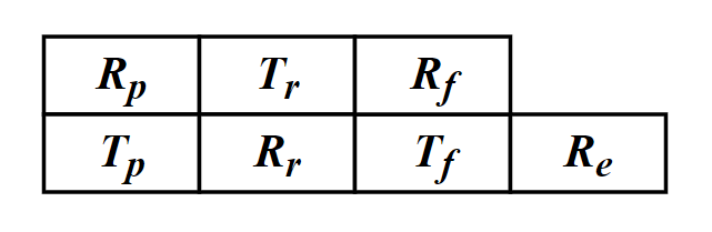
As mentioned above, six timestamps (Tp, Rp, Tr, Rr, Tf, Rf,) are needed to calculate the ToF. Therefore, for each neighbor, an additional data structure is designed to store these timestamps which we named it the ranging table, as shown in Fig.4. Each device maintains one ranging table for each known neighbor to store the timestamps required for ranging.
Let’s focus on a simple scenario where there are a number of Crazyflies, A, B, C, etc, in a short distance. Each one of them transmit a message that can be heard by all others, and they broadcast ranging messages at the same pace. As a result, between any two consecutive message transmission, a Crazyflie can hear messages from all others. The message exchange between A and Y is as follows.
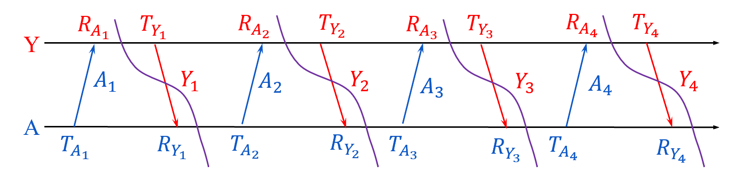
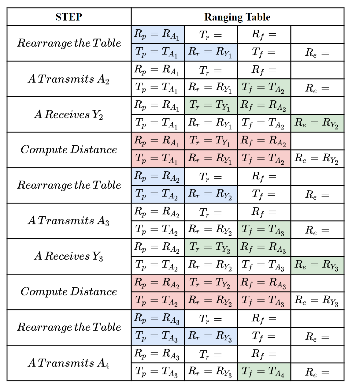
The following steps show how the ranging messages are generated and the ranging tables are updated to correctly compute the distance between A and Y.
The message exchange between A and Y could be also A and B, A and C, etc, because they are equal, that’s means A could perform the ranging process above with all of it’s neighbors at the same time.
To handle dense and dynamic swarm, we improved the data structure of ranging table.
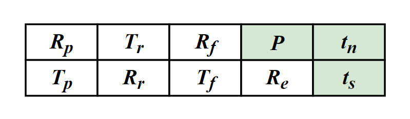
There are three new notations P, tn, ts, denoting the newest ranging period, the next (expected) delivery time and the expiration time, respectively.
For any Crazyflie, we allow it to have different ranging period for different neighbors, instead of setting a constant period for all neighbors. So, not all neighbors’ timestamps are required to be carried in every ranging message, e.g., the receive timestamp to a far apart and motionless neighbor is required less often. tn is used to measure the priority of neighbors. Also, when a neighbor is not heard for a certain duration, we set it as expired and will remove its ranging table.
If you are interested in our protocol, you can find much more details in our paper, that has just been published on IEEE International Conference on Computer Communications (INFOCOM) 2021. Please refer the links at the bottom of this article for our paper.
Implementation
We have implemented our swarm ranging protocol for Crazyflie and it is now open-source. Note that we have also implemented the Optimized Link State Routing (OLSR) protocol, and the ranging messages are one of the OLSR messages type. So the “Timestamp Message” in the source file is the ranging message introduced in this article.
The procedure that handles the ranging messages is triggered by the hardware interruption of DW1000. During such procedure, timestamps in ranging tables are updated accordingly. Once a neighbor’s ranging table is complete, the distance is calculated and then the ranging table is rearranged.
All our codes are stored in the folder crazyflie-firmware/src/deck/drivers/src/swarming.
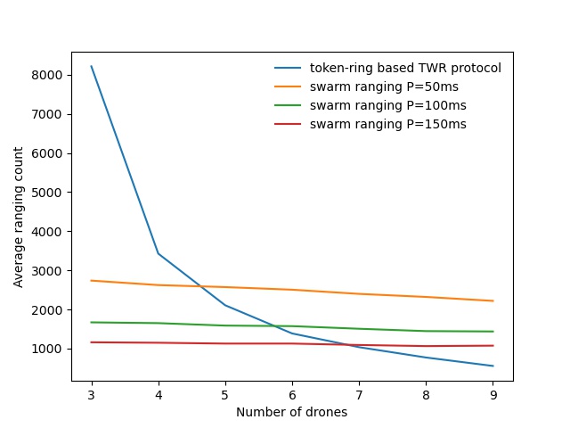
The following figure is a ranging performance comparison between our ranging protocol and token-ring based TWR protocol. It’s clear that our protocol handles the large number of drones smoothly.
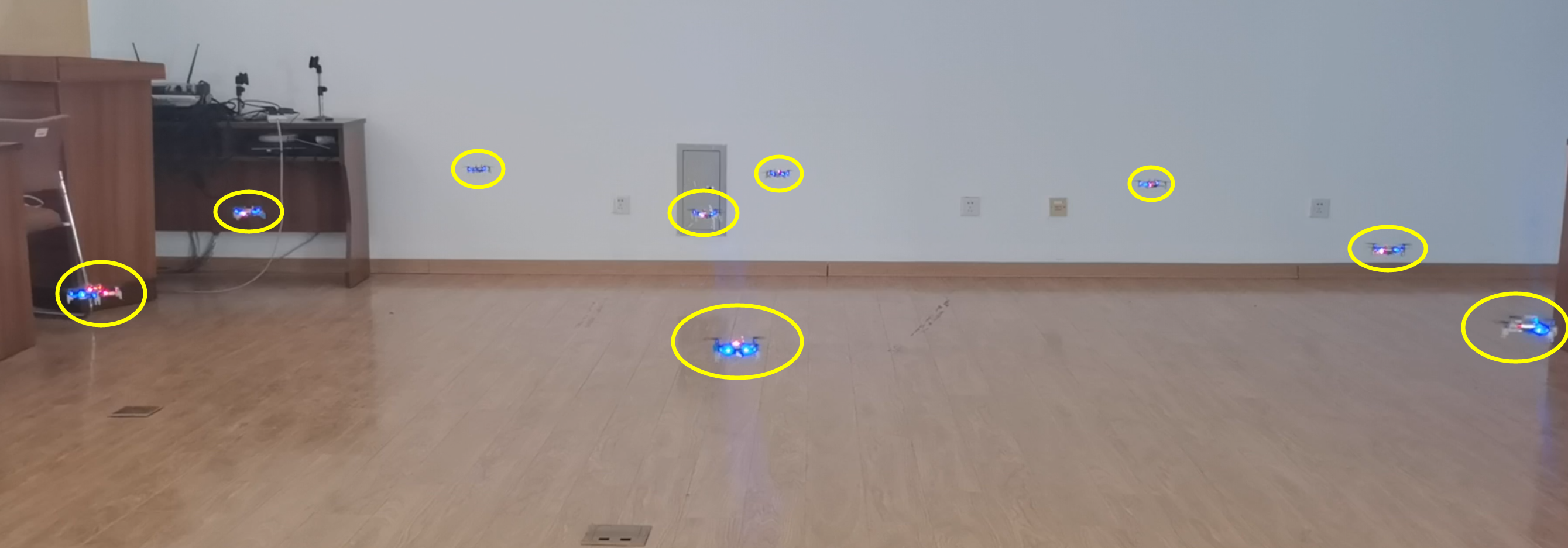
We also conduct a collision avoidance experiment to test the real time ranging accuracy. In this experiment, 8 Crazyflie drones hover at the height 70cm in a compact area less than 3m by 3m. While a ninth Crazyflie drone is manually controlled to fly into this area. Thanks to the swarm ranging protocol, a drone detects the coming drone by ranging distance, and lower its height to avoid collision once the distance is small than a threshold, 30cm.
Build & Run
Clone our repository
git clone --recursive https://github.com/SEU-NetSI/crazyflie-firmware.git
Go to the swarming folder.
cd crazyflie-firmware/src/deck/drivers/src/swarming
Then build the firmware.
make clean
make
Flash the cf2.bin.
cfloader flash path/to/cf2.bin stm32-fw
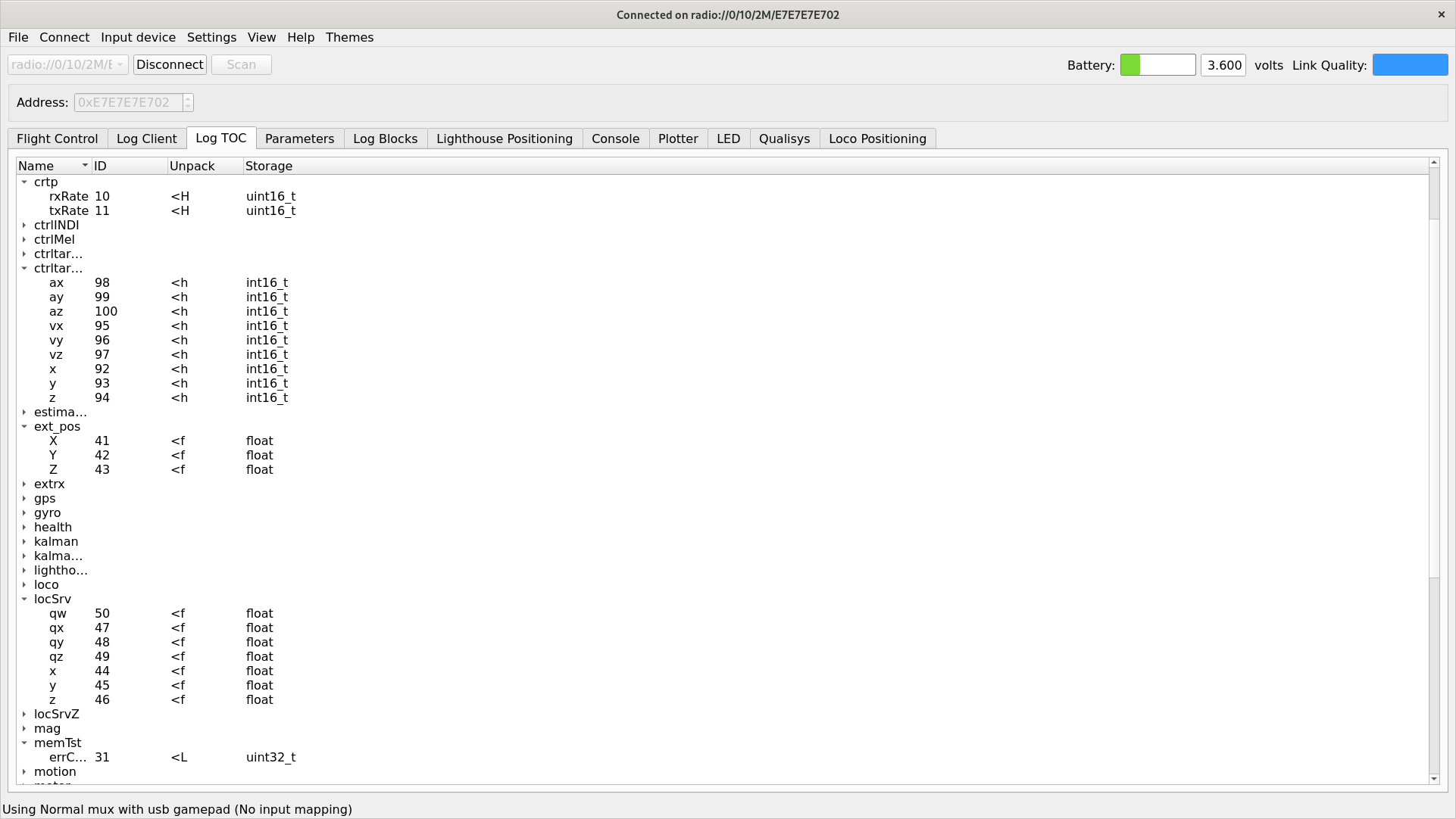
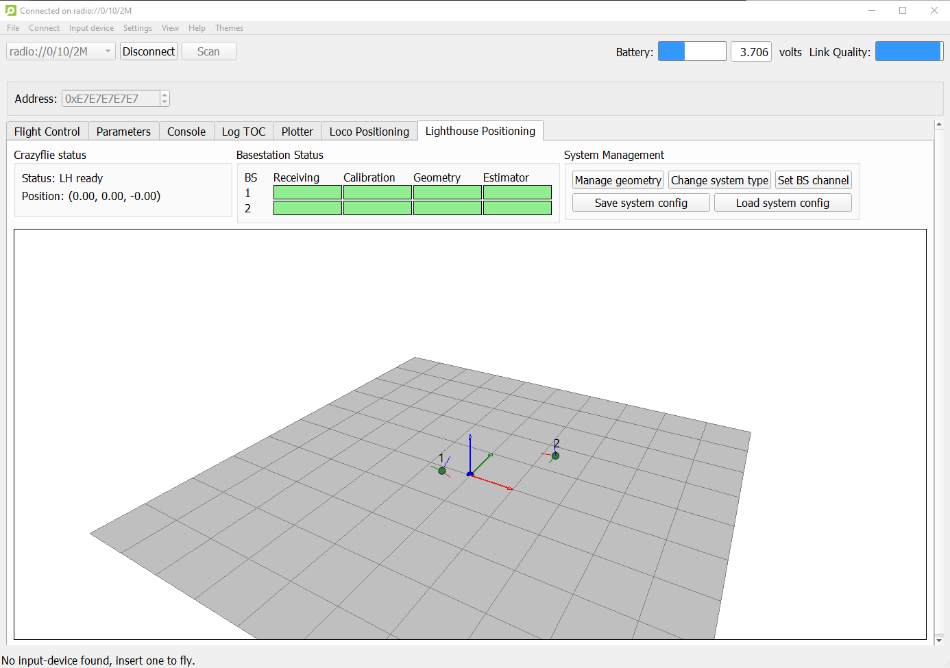
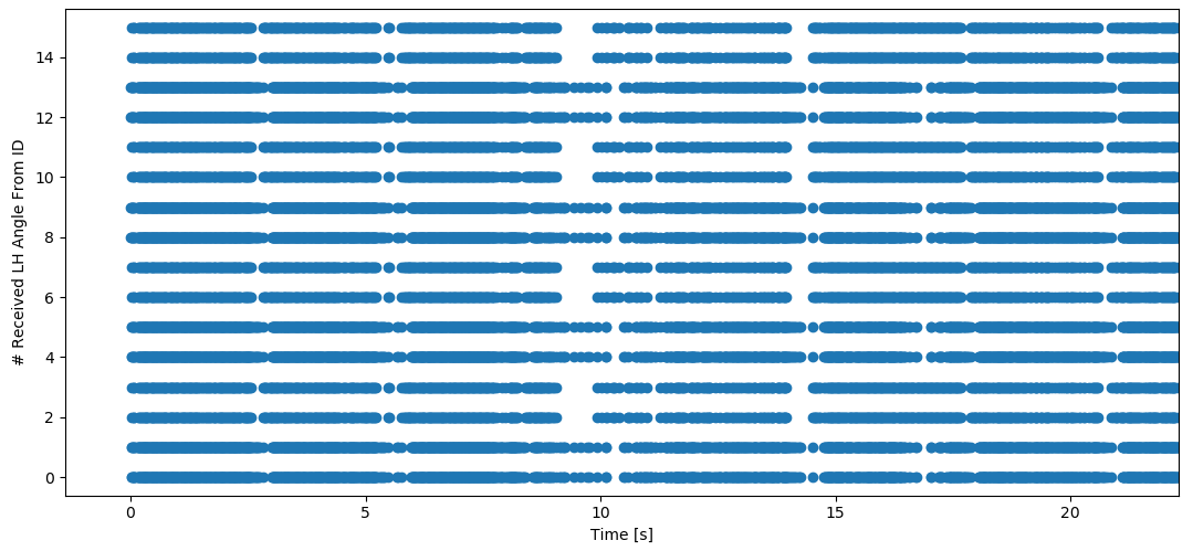
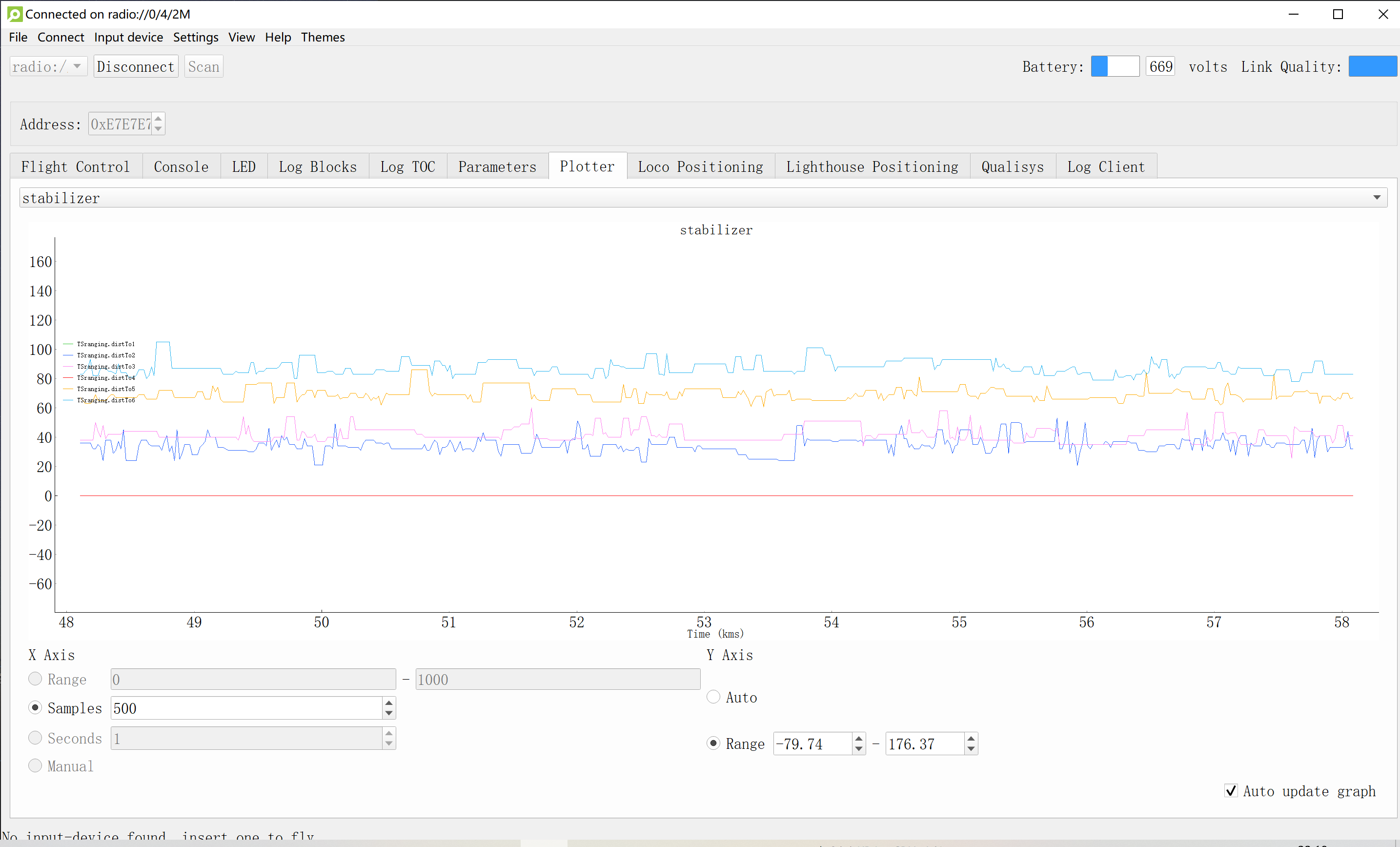
Open the client, connect to one of the drones and add log variables. (We use radio channel as the address of the drone) Our swarm ranging protocol allows the drones to ranging with multiple targets at the same time. The following shows that our swarm ranging protocol works very efficiently.
Summary
We designed a ranging protocol specially for dense and dynamic swarms. Only a single type of message is used in our protocol which is broadcasted periodically. Timestamps are carried by this message so that the distance can be calculated. Also, we implemented our proposed ranging protocol on Crazyflie drones. Experiment shows that our protocol works very efficiently.
Related Links
Code: https://github.com/SEU-NetSI/crazyflie-firmware
Paper: http://twinhorse.net/papers/SZLLW-INFOCOM21p.pdf
Our research group website: https://seu-netsi.net
Feng Shan, Jiaxin Zeng, Zengbao Li, Junzhou Luo and Weiwei Wu, “Ultra-Wideband Swarm Ranging,” IEEE INFOCOM 2021, Virtual Conference, May 10-13, 2021.