We are thrilled to announce the new 2022.1 release of the Crazyflie firmwares, library and client! There have been a lot of bug fixes, polishing and new features and we are glad we finally get to share it with all of you.
Noteworthy features and fixes
The features and fixes listed here is only a subset of all the bug fixes and other additions we have done in the last six months. For a more complete view, please check the release notes on GitHub.
Along with all the new features, bug fixes and general polish of our software we have also spent time making sure our documentation is up-to-date and relevant! You can check it out on our website. Do not forget to check out the individual repositories documentation. And the tutorial page has gotten some love this cycle, check it out!
Please go forth and install this new release and please file issues with any problem you find!
Where to get it?
The firmware images for the Crazyflie STM firmware and the Crazyflie NRF firmware should already be available through the cfclient. And if you want to download them yourself you can find them at https://github.com/bitcraze/crazyflie-firmware/releases.
The Crazyflie Client and the Crazyflie Python library are available through Pypi (The Python Package Index), to install them you can use the following commands:
$ python3 -m pip install --upgrade cfclient # to install or upgrade the Crazyflie client
$ python3 -m pip install --upgrade cflib # to install or upgrade the Crazyflie Python libraryCode language:PHP(php)
Base station geometry estimation is a function in the python client (in the lighthouse tab), where the system estimates the position and orientation of the base stations. The user places the Crazyflie on the floor (in the desired origin) and clicks a button to measure the angles to the base stations, which are used to estimate the geometry. The current implementation is fairly basic and has some issues associated with it:
All base stations must be received from the point where the Crazyflie is located
Only 2 base stations are supported
The coordinate system is not properly aligned with the room
The generated geometry is not as good as it could be, that is the position/orientation is sub-optimal
The code has a dependency to OpenCV which causes problems for ROS users
I have been working on a solution for these problems as my fun Friday project and in this blog post I will tell you a bit more about the problems and a possible solution.
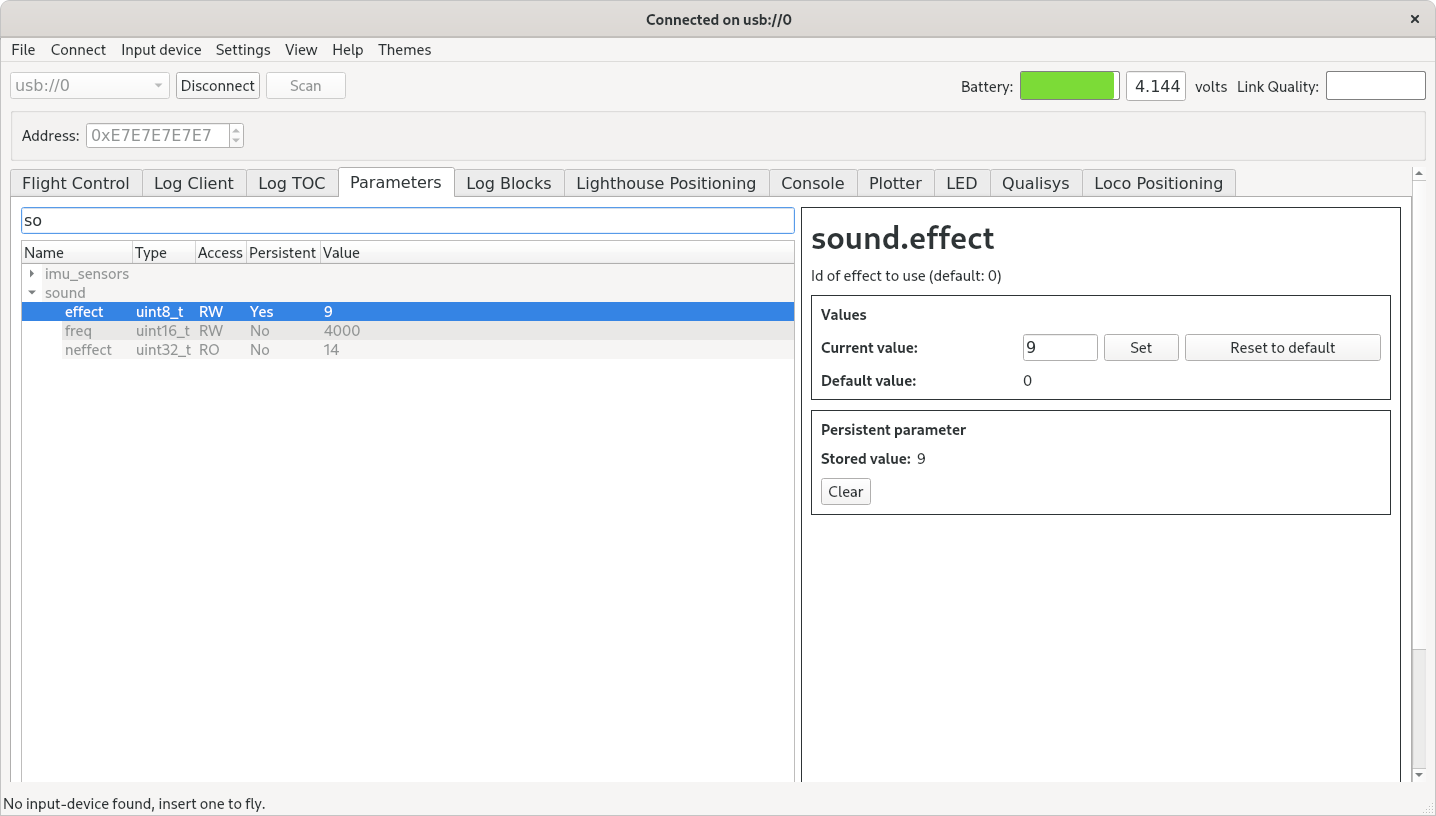
Screenshot from the client of a geometry with 4 base stations.
What are the problems to be solved?
In the current implementation, the user places the Crazyflie in the origin, with the front of the Crazyflie pointing in the direction of the positive X-axis. When the user hits the “Estimate Geometry” button, the angles to the visible base stations are recorded and the solvePnP() function in OpenCV is used to estimate their poses (position and orientation). This is all fine but it also has its limitations and in the following section we will outline what the limitations are and how to solve them.
All base stations must be received in the origin and only 2 base stations are supported
Currently the Crazyflie ecosystem supports up to 2 base stations and this works fine for a flight space of around 4×4 meters. With more base stations it would be possible to cover larger areas or multiple rooms, which is a feature that many users have been asking for. In these scenarios it will not be possible to receive all base stations from one position any more though, and it will require a new method for geometry estimation using multiple measurements. Suppose base station 1 and 2 are received in one position and 2 and 3 in another, then we can map the measurements together since we know base station 2 must have the same pose in both measurements. This way it is possible to relate all base station poses to each other, provided there are measurements that link them together.
The coordinate system is not properly aligned with the room
When generating the geometry in the current implementation, the orientation of the Lighthouse deck is used to define the coordinate system: forward of the deck defines the X-axis, left defines the Y-axis and up the Z-axis. The problem is that the deck might not be perfectly aligned with the Crazyflie, the floor might not be completely flat or the Crazyflie might not point exactly in the desired direction. A pretty small misalignment will result in fairly large errors a couple of meters away, resulting in unexpected behavior, for instance not flying at constant height. Expanding to more base stations and larger systems, the problem will become even bigger and a better solution is clearly needed.
If we used the position of the Crazyflie when placed at multiple positions, we could use this information to rotate the coordinate system to be better aligned. For instance, suppose we measured some points on the floor of the flight space, then we could make sure the XY-plane of the coordinate system goes through those points, or at least as close as possible. Similarly one or more measurements along the X-axis would help to define the rotation around the Z-axis.
The generated geometry is not as good as it could be
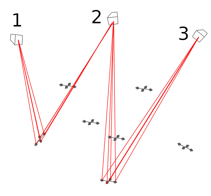
The lighthouse positioning system is based on measuring the angles between the sensors on the Lighthouse deck and the base stations. One can think of it as four beams or rays, going from each base station to the sensors on the deck, for which we measure the direction very precisely seen from the base station’s point of view. The purpose of the geometry estimation is to figure out the position and orientation of the base stations so that we can calculate how the beams are oriented in the flight space instead. By looking at where the beams from two base stations intersect we know where the sensors are located and can calculate the position of the Crazyflie. This is a somewhat simplified picture of how it works but it is sufficient for the following discussion.
So what happens if the geometry is not completely correct? If the estimated positions or orientations of the base stations are slightly off, the beams will not intersect and we have to use some method to find the point closest to the two beams instead to use as the sensor position. In a real world system there will always be errors and the implementation must be able to handle them, but we want to keep them as small as possible. Further more we want to make sure the errors are uniformly distributed in the flight space so that we get equally good results everywhere.
In the current estimation process, where we take a measurement in one position, we are able to generate a geometry that is good at that point, but due to noise in the measurements and other subtleties the error at the edges of the flight space might be several centimeters.
The solution to this problem is to measure the angles in multiple positions and try to find a geometry where the error is equally small for all of them. It does not guarantee that the error will be equal everywhere, but if we make measurements in the volume we plan to fly in we know it will be OK where we need it to be. It should also be a much better geometry, for the full covered volume, than what we can be achieved by measuring in one point only.
One bonus problem that hopefully will be solved by this approach is the moving back and forth that sometimes can be seen in a Lighthouse 2 system. What happens is that the base stations interfere with each other from time to time (by design) and most of the time the Crazyflie gets positioning information from both base stations, but every couple of seconds only from one of them. When both are available the “average” position is used, but when only one is received, the Crazyflie will “jump” to the position indicated by that base station (the simplified model from above with crossing beams does not hold in this case, sorry!). If the difference between the suggested positions of the two base stations (the error in the geometry) is large there will be a noticeable motion in the Crazyflie.
The code has a dependency to Open CV
In the current solution we use the solvePnP() function in Open CV to estimate the geometry. Open CV is an awesome library but unfortunately it has turned out that this dependency interferes with ROS, and since a fair amount of our users also use ROS, we would like to get rid of it if possible.
Luckily I found an open source implementation of IPPE, an algorithm that finds the pose of an object based on points seen by a camera, that we can use instead. There is actually an option to use Ippe in OpenCV’s solvePnP(), but we used another flavor.
The solution
The core idea is to first collect measurements of beams in many positions in the flight space by moving a Crazyflie around and record the lighthouse angles. Secondly an equation system is created that takes the poses of the base stations and all the recorded Crazyflie poses as input and as output calculates the lighthouse angles those poses would correspond to for all the sensors. Finally the output is compared to the recorded values and poses are adjusted using the least-square solver in scipy to find the poses that minimizes the difference between the measurements and the output from the equation system.
Before we can solve the equation system we have to record the angles from the base stations. There is a handy function in the Crazyflie that pushes measured lighthouse angles to the PC via the radio, and by letting the user move the Crazyflie around in space we get the angles along that path. What we are looking for though are angles collected in discrete positions and as an approximation I group measurements together based on time. The assumption is that if two angle measurements are closer than 10 ms in time, the Crazyflie did not move very far and they can be considered to be taken in the same position. The output of this process is a list of samples where each sample contains the measured lighthouse angles of one or more base stations for one specific Crazyflie pose. After this has been done, the list is filtered to only contain samples with two or more base stations.
We also need an initial guess of the base station and Crazyflie poses for the least-square solver to make the solution converge. I use IPPE for this and use the first sample as the reference to define a temporary global reference frame. Suppose the first sample contains angles for base stations 2 and 3, we can then use IPPE to calculate an estimate of the pose of the two base stations, in the Crazyflie reference frame of this sample. Since we use the first sample as the reference for the global reference frame (that is the pose of the Crazyflie in this sample is the origin by definition), those poses are also equal to the base station poses in the global reference frame.
Suppose the next sample contains lighthouse angles for base stations 1 and 2, using IPPE we can estimate the base station poses for base stations 1 and 2 in the reference frame of the Crazyflie in this sample. Since the relative positions of the base stations is the same, regardless of reference frame, we can rotate/translate the poses of the base stations so that base station 2 pose matches the pose of base stations 2 in the first sample. We now have an estimate of the poses of base stations 1, 2 and 3, further more the transformation used represents the pose of the Crazyflie in sample 2. Repeating the process for all samples gives us a pretty good idea of where all the base stations are located as well as the pose of the Crazyflie in all the samples.
We can now feed the initial guess and the equation system into scipy and hopefully get a refined solution back. From the estimated poses of the base stations and Crazyflie samples it is possible to calculate the distance between sensors and beams which gives us an approximation of how good the solution is.
The final step is to align the coordinate system with the room, as mentioned earlier the solution we have this far is based on the pose of the Crazyflie in the first sample. The way it is done in the suggested implementation is to ask the user to place the Crazyflie at some points in the desired origin, on the positive X-axis and in the XY-plane and measure the angles in these positions. The measurements are included as samples in the above process which means we will get the estimated positions as a part of the over all solution, in the temporary global reference frame. The task at hand is then to find the rotation/translation from the temporary global reference frame to the one indicated by the positions sampled by the user. Again we do a least-square optimization to find the transformation that minimizes the error in the sampled points. We can now calculate the final solution by applying the transformation to the base station poses we got earlier.
Does it work?
Yes, it seems to work pretty well, I have not had the time to do extensive testing yet but the results looks promising. In our flight arena with 4 base stations, the solution seems to generally be acceptable. We don’t know the exact poses of our base stations since it is very hard to measure, but they are mounted in the same truss and should be at similar heights.
The above snippet is part of the output from one run and as can be seen the estimated height is between 2.96 and 3.02 m. You can also see that the estimated average error for sensor positions is in the order of 2-3 mm while the maximum error is 1.5 cm.
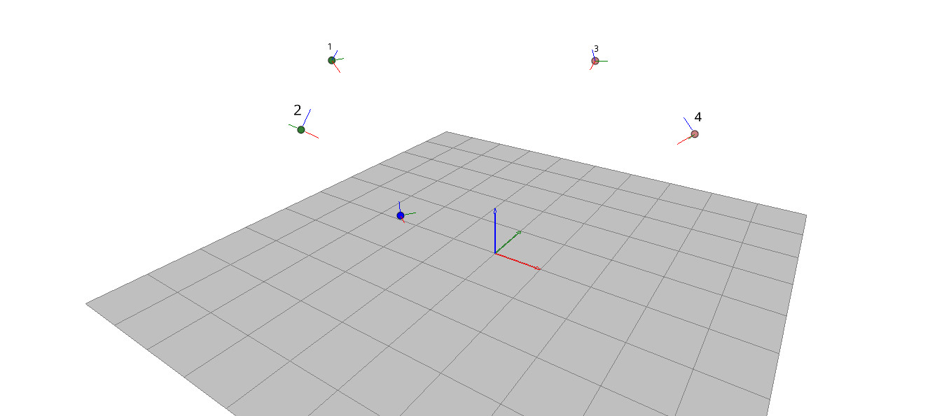
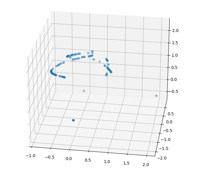
Below is graph of the recorded Crazyflie positions in the final solutions. Note the three single points at the bottom that are from the origin, the X-axis and XY-plane.
Estimated positions of the Crazyflie
I did some testing on larger systems with 6-8 base stations this Friday and it seemed to be harder to get a solution that converges which indicates that there might be something to look into here.
Try it out
This is still work in progress, but if you want to try it out, you can find the code in this pull request. Run the examples/lighthouse/bs_geometry_estimation.py script, you will get instructions on the screen as you go.
Officially the firmware supports 2 base stations , but most of the code is designed to handle up to 16 and if you want to test the functionality with more than two base stations you have to update PULSE_PROCESSOR_N_BASE_STATIONS and re-flash your Crazyflie.
In this blogpost we will teach you how to fly the Crazyflie beyond edges without crashing, using only on-board sensors. Come join in!
Safe flights across edges are achievable!
Introduction
UAVs have seen tremendous progress in the last decades and have since moved from research labs to various real-world environments. Small UAVs (so-called micro air vehicles, MAVs) like the Crazyflie open up even more possibilities. For example, their size allows them to traverse narrow passages or fly in cluttered environments (as recently showcased in this blog post). However, in order to achieve these complex tasks the community must further improve the cognitive ability of these MAVs in order to avoid crashes.
One task on this list and today’s topic is the possibility to fly at constant altitude irrespective of the terrain. This feature has been discussed in the community already two years ago. To understand the problem, let’s look at the currently implemented solution: With the Flow deck mounted the Crazyflie uses a 1D lidar sensor to estimate its vertical position. This vertical position (more or less) equals the current sensor reading. On flat floors this solution works very well. However, if the Crazyflie shall traverse through a narrow window or fly above irregular terrain its altitude will change based on the sensor readings. This can lead to unstable flights, as in the following video, or even crashes!
You might wonder: why not use any of the other great tools from the Bitcraze universe? Indeed, the Lighthouse positioning system and the Loco positioning system work well for absolute positioning (as we have seen earlier, e.g., in this blog post). However, the required setups are often not available in difficult environments. Alternatively, the barometer could be used to achieve a solution based solely on on-board sensors. In fact, Bitcraze has proposed an altitude hold functionality a few years ago. This is a cool feature, but its positioning accuracy of “roughly ±15cm” is not fully satisfying. Finally, relying on the on-board IMU alone will inevitably lead to drifting over time.
Thus, we propose a solution based on the Flow deck and the Multiranger deck. This approach, only based on on-board sensors, allows to fly at constant altitude with obstacles above, below, or even both above and below the Crazyflie. Kristoffer Skare developed this solution when he worked with us as an intern in 2021.
Technical Description
As a first step, the upward-facing lidar of the Multiranger deck is incorporated in the same way the downward-facing lidar of the Flow deck is used in the firmware. This additional measurement can then be used in the extended Kalman filter (EKF) to improve the state estimation. Currently, the EKF estimates and outputs 1 value for the altitude. For our purpose two more states are added to the EKF: one state is defined as the height of the object under the Crazyflie compared to the height where the altitude state is defined as 0. Similarly, the other state is defined as the height of the object above the Crazyflie compared to the same reference height. The Crazyflie keeps therefore track of the environment in order to keep its own altitude constant. To achieve this, an edge detection was implemented: The errors between the predicted and measured distance are tracked in both the upward or downward range measurement. If either of these errors is too large the algorithm assumes that the floor or roof has changed (while the original EKF would think the drone’s position has changed, triggering a change in thrust). Thus, the corresponding state gets updated. For more details on the technical implementation and the code itself, check out our pull request.
Results
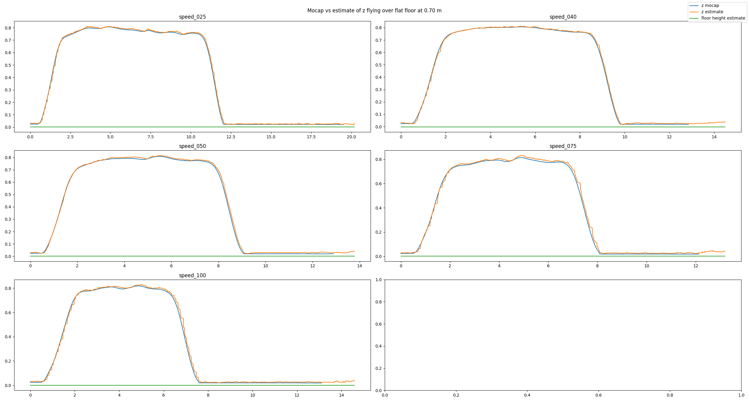
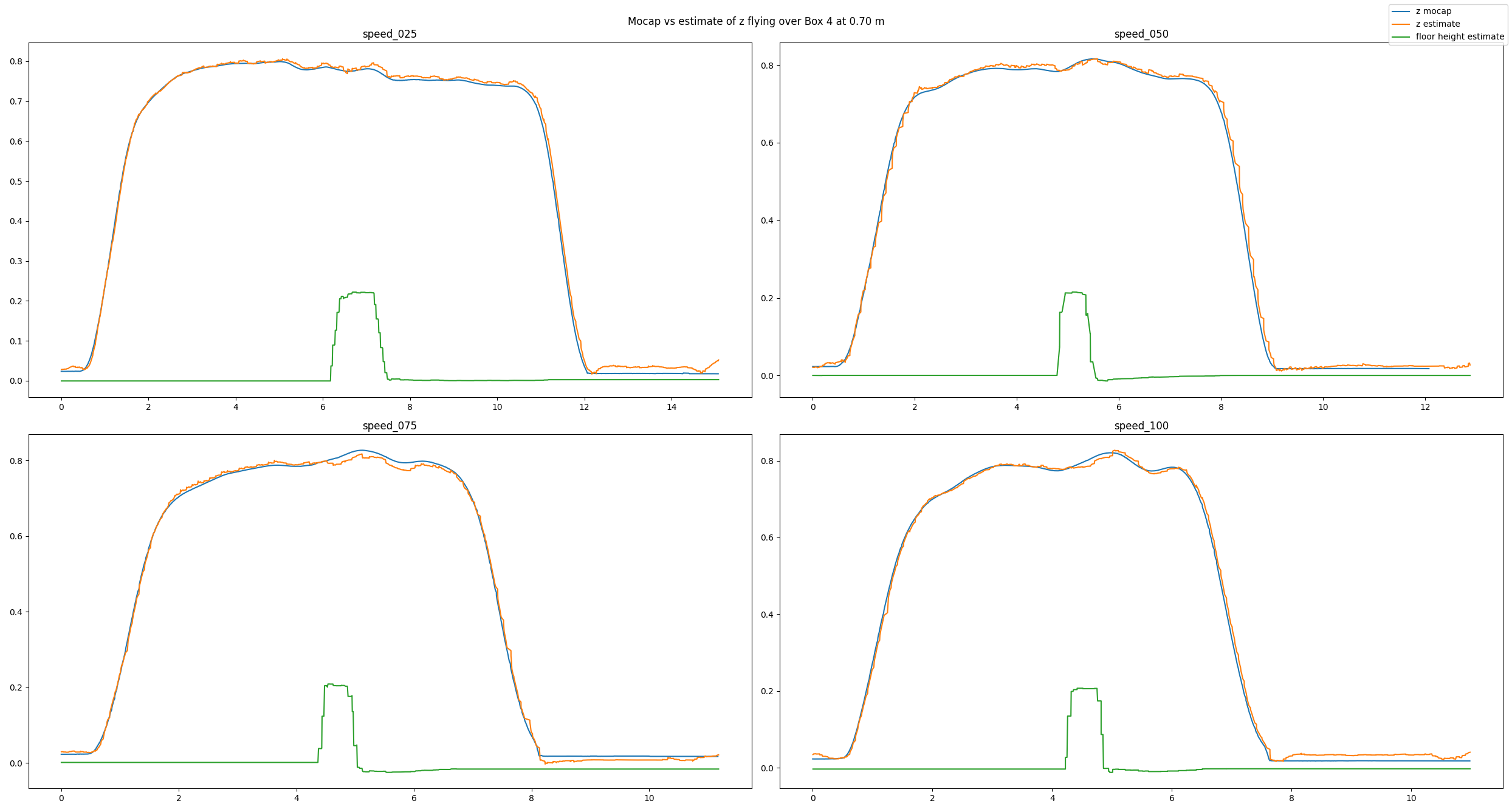
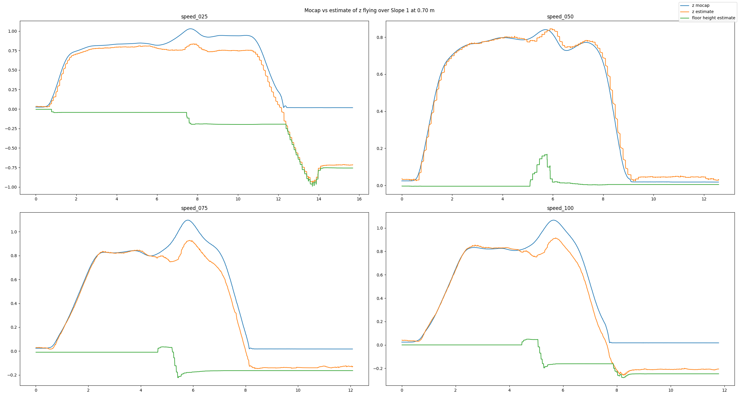
To analyze our approach we have used a Qualisys motion capture system. We have conducted many different tests: flying over different obstacles, flying at different velocities, flying at different altitudes, or even flying under different lighting conditions. Exemplarily, in this post we will have a look at a baseline example, a good estimate, and a bad estimate. In each picture you can see the altitude (in meters) over time (in seconds) for different flight speeds (in centimeters per second). You will see three lines: The motion capture ground truth (blue), the altitude estimated by our code (orange), and the new state keeping track of the floor height (green). For each plot, the Crazyflie takes off, flies in positive x direction, and lands.
In the baseline experiment, it flies over a flat floor. Clearly, the altitude estimates follow the ground truth values well, and the floor is correctly estimated to be flat.
Baseline experiment flying over a flat floor
In the next example, we have added a box with an approximate height of 0.225 m and made the Crazyflie fly over it. Despite the obstacle the altitude estimates follow the ground truth values well. Note how the floor estimates indicates the shape of the box.
Experiment flying over a box
Because the algorithm is based on an edge detection, we had a hunch that smoothly changing obstacles will pose a problem. Indeed, the estimates can be messy as we see in the next example. Here, the Crazyflie flies over an orthogonal triangle, with the short leg at 0.23 m pointing upwards and the long leg with 0.65 m pointing in flight direction (thus forming a slope). For different flight speeds different the estimates turn out quite differently.
Experiment flying over a slope
If you don’t like looking at plots, check out this video with some cool shots instead!
Conclusion
To summarize, we propose a solution for constant altitude flight with Crazyflies, using the Flow deck and the Multiranger deck. We have tested it successfully under various circumstances. Still, we see some potential for improvement, e.g. when dealing with slopes. In addition, the current implementation is quite a change to the original EKF, which poses a problem for integration.
Thus, a way forward can be an out-of-tree build to ease the use of the solution for the community. At SINTEF we certainly plan to deploy this code in all of our tests in 2022, which will hopefully allow us to gather more experience and thus find further ways to improve or tune the system.
We want to emphasize that this is not a perfect solution. That means a) you should use it with care and b) you are very much welcomed to contribute. E.g. feel free to chime in in the pull request, test the code in your environments, propose improvements, or implement an out-of-tree build! :) Maybe you can even come up with an alternative approach for constant altitude flights?
If you want to check out more of our work, visit our website. Also, keep reading this amazing blog from Bitcraze as we try to be back some day (if Bitcraze wants us hehe)!
I have returned from my family visit in California, who I’ve haven’t seen them in 3 years due to Covid. To spend the most possible time with them, the plan was that I would still work full time for Bitcraze from my father’s home. The problem became however, that it wouldn’t fit so well in our current way of work as I would miss all the morning stand up meetings due to the large time difference between Sweden and California (-9 hours). That is why we settled that I would work on separate projects/investigations during my time away. So I thought it would be a great opportunity to dig into ROS and 3D simulations again and see what the latest state of that is! So about the simulations is what I’ll be mostly talking about right in this blog post, in terms of what simulators are out there and what simulation development is currently ongoing.
Need for simulation?
Why would it be actually be necessary to have a simulation in our current frame work? Just to give an example, my new colleague Jonas recently tried out his hand on the CFlib swarm class for the first time for the BAMdays tutorials, and simulator would have been great during that initial porcess. Namely, most of the crashes were not necessary due to low batteries or bad communication, but mostly due to the fact that he was not able to double check his script beforehand. If one is able to check if all the programmed positions of the Crazyflies are implemented as they should before an actual flight, this would prevented a lot of broken propellers!
Just to note here that there are a lot of types of simulations that you can think of. Earlier this year had our ex-interns Max and Josephine finish an Renode simulation of the Crazyflie’s microcontrollers. We’ve also seen the word Simulink pop-up multiple times on the forum which indicates that quite some control classes are investigating the dynamic model of the Crazyflie. However, the type of simulation that I’m currently referring to are the 3D simulators in which a robot or quadcopter can move and interact with a virtual environment, with usually an physics engine in effect.
Crazyflie in Gazebo (+ROS)
During some initial investigation there were already some simulations that pop out. First of all I went and looked into what is available for Gazebo at the moment, which is:
CrazyS is based on the RotorS simulation with some additional off-board crazyflie controllers for position control. I wasn’t able to build it for my Ubuntu 20.04 just yet myself, but that there is ongoing work to port CrazyS to ROS Noetic. For now on a virtual machine with ROS melodic it build just fine! Note my laptop did had to work quite hard when I wanted to simulate more than 1 Crazyflie, but the physics and plugins that were made for Gazebo is enabling many to do a lot for their research. Please check out the core papers about CrazyS!
Sim_cf is perhaps a little lesser known, but the project does stand out as it has some interesting features to it. It is for instance, possible to use the actual c-based firmware in software-in-the-loop (SITL) mode, which controls the simulated Crazyflie. It is even possible to use an actual crazyflie with an hardware-in-the-loop (HITL) simulation. Eventhough the project is not actively maintained anymore, I did manage to build it from source for ROS Noetic and Gazebo 11, although I was not able to fly more than 4 do to errors.
Other Simulators
Ofcourse Gazebo is not the only possibility out there. I also had a quick go at another simulator called Webots, which is quite an interesting option indeed as well. Currently there is only one quadcopter model available, so it only makes sense for it to also contain an Crazyflie! They do use their own robotic format, so probably the easiest process would be, is to convert an existing model for Gazebo/ROS into an format that Webots can understand.
So in the future, the current Gazebo in its form will disappear and will be only be part of Ignition. So that is why it made sense for me to start playing with an separate Crazyflie model and plugins for the Ignition frame work instead. Moreover, it seems that quite some elements and plugins based on the RotorS simulation for the original gazebo, are now fully integrated within the Ignition gazebo framework, which should make it more easier to make quadcopter models fly. Currently it’s still work in progress, so right now is only to be found on my personal github repository, but as soon as it becomes more fleshed out and stable, this will probably transferred to Bitcraze’s github repos and we will write a more elaborate blogpost about it. For now, I’ll try to work on it further as my Fun Friday project!
In the mean time, we have started a simulation discussion thread in the Crazyswarm2 repository, which is an ongoing port of Crazyswarm to ROS2. It would be the ideal situation if we would be able to use this simulator for both Crazyswarm and our native CFlib! But I’ve mostly have used Gazebo in the past, so if there are any other simulators that we should try out too, please join the discussion and let us know!
Sometimes we get the question of where to modify or add code to change some behavior of the Crazyflie. There is no quick answer to this question but we thought that we should write a post to clear up some question marks and give a better idea of how to approach the problem.
There are quite a few repositories on the Bitcraze github page but there are two that are the main focal point for almost any Crazyflie work, those are the crazyflie-firmware and the crazyflie-lib-python. The crazyflie-firmware contains the source code (written in C) for the firmware that runs in the Crazyflie, that is the code responsible for flying, blinking LEDs, communicating with the radio, scanning sensors and so on. The crazyflie-lib-python (often called the python lib) on the other hand is running on the PC side and is the API to use to communicate with the Crazyflie from a script. The crazyflie-lib-python is also used by the python client which means that anything you see in the client can be done by a script using the python lib.
Let’s assume we have a system of one Crazyflie connected to a computer using a Crazyradio. Now we want to control the Crazyflie and make it take off for instance, how should this be done?
The easiest way would be to use the python lib. The python lib is used to communicate with the Crazyflie and we can use it to send instructions to the Crazyflie, for instance to take off or fly a trajectory. It is also possible to use the parameter framework to change values in the Crazyflie. The main way of monitoring what is going on in the Crazyflie is to use the log framework to read variables from the Crazyflie. The python lib is perfect for controlling the Crazyflie or prototype ideas as it is very fast to make changes and try things out. The best to get started with the python lib is to start from an example that already uses functionalities you want to use.
Another option is to add code in the firmware. Originally this has been quite hard since the firmware has not been initially designed to accept user code. This means that unless you want to modify an already existing code, it is quite hard to find where to add your code so that it runs in the Crazyflie firmware and you would have to make a fork of the firmware which can he hard to maintain and keep up to date in the long run. This is one of the things the out-of-tree build and the app layer is solving, it is now quite easy to add and run your own C files to the firmware in your own project without having to fork the Crazyflie firmware. There is a bunch of examples in the firmware that shows how to implement autonomous behavior as an app. The easiest is to start with the hello world example. When it comes to modifying exiting functionality in the firmware code, most of the time forking and modifying the official firmware unfortunately is the only solution. We are however working our way to make more and more of the firmware modular so that it can be expanded out of tree. For example there has been work to make an out of tree estimator possible to implement.
A prototype written as a python script is often pretty easy to move to the Crazyflie firmware. This is a good pattern when writing an application, rapid prototyping in python and then finalizing in firmware if needed. The best example of that is the push demo. It is a demo where the Crazyflie can be pushed-around with the help of the flow deck for autonomous flight and the multiranger deck for detecting obstacle/hands. We have a python cflib push demo as well as a Crazyflie firmware push demo app.
There is some support in the python lib for interacting with multiple Crazyflies and it is probably a good start point for simple swarms. For more advanced swarm work Crazyswarm may be a better option.
If you would like to see some of the process in action, we have made a workshop during our BAM days about implementing functionality both using the python lib and in the firmware as an out of tree app:
We have recently worked on functionality in our web site to generate documentation from source in a few ways that we hope will improve the quality as well as simplify maintenance. We have already written a bit about the log and param documentation in the crazyflie-firmware repository, but we now also added and API reference in the python library as well as generating a list of publications related to the Crazyflie.
The Log and Param documentation
Earlier this year we worked on generating documentation for Log and Params from doxygen comments. We will not dig deeper into this here, but you can read more about it in this blog post. The latest version is available on our web in the repository documentation for the crazyflie-firmware: logs and params
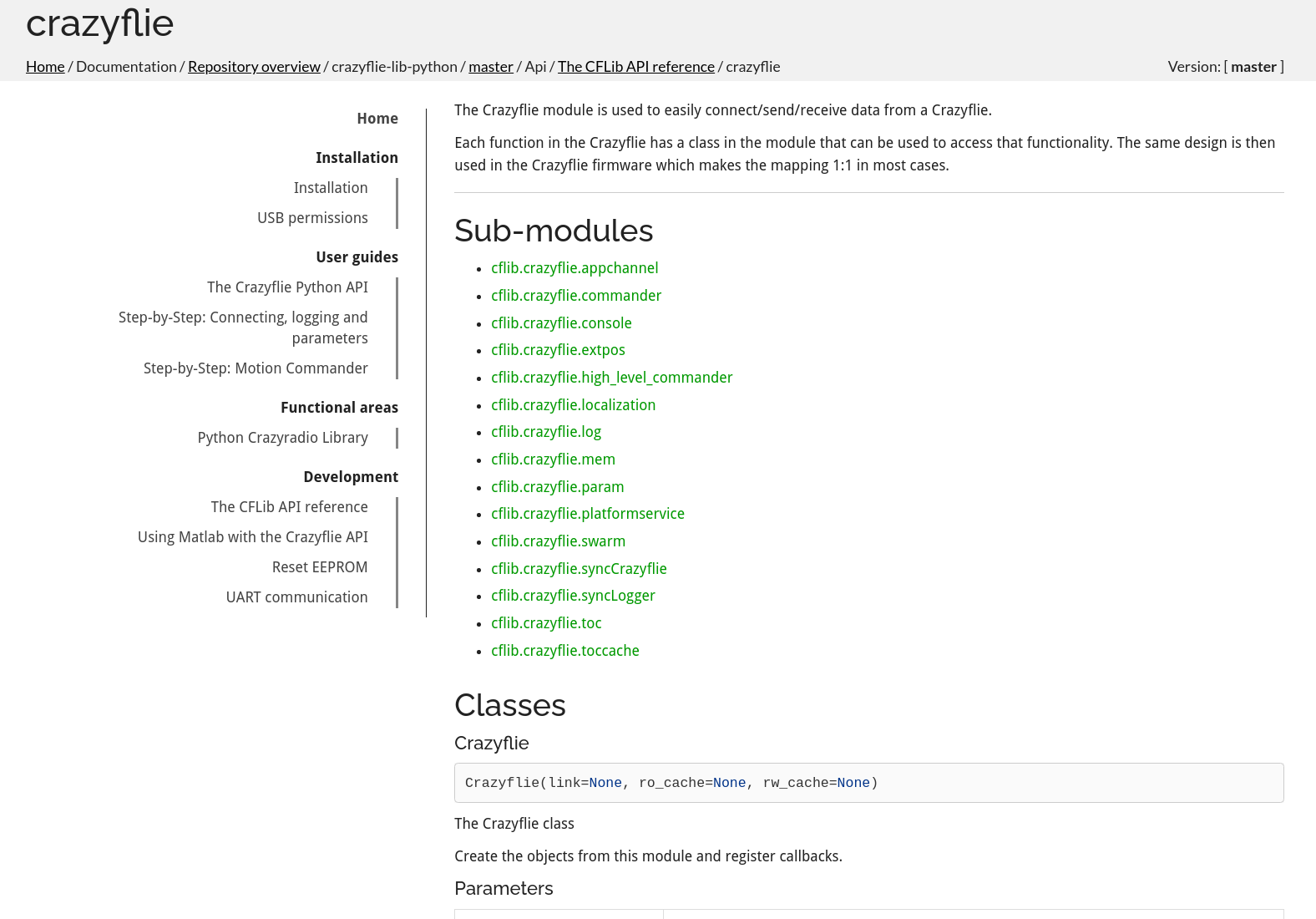
However along the way we have also added comments and examples to our code. And this, combined with the way we have structured the library actually enables us to automagically generate reference API documentation. That is, something that shows you everything that is possible to do with the library, all modules and classes, all methods and constants that the library offers.
After some recent work this is now happening and the documentation will now get generated each time we deploy our website!
The API reference documentation can be found in the repository documentation for the library. Please check it out! And be picky, complain where the documentation is lacking! Or if the formatting seems weird! We are trying to get the hang of this and we need you to push us!
Managing publications
Some years ago we started to add publication that are related to the Crazyflie to our Research page, we hope that it might be inspiring to read about all the awesome things that the Crazyflie is used for.
Until now it has been a simple list in markdown but with an increasing number of publications it has become harder and harder to maintain it, finally we have put the work into generating the list from a BibTeX (.bib) file instead. One advantage of the new solution is that BibTeX is a well known format to the research community with lots of tools around to manage BibTeX files while another improvement is that the list will be formatted in a consistent manner (which was not always the case earlier).
If you want to add a publication to the page, simply update the .bib file with your data and create a pull request with the changes. We will merge when appropriate and the publication will become visible on the web after the next deploy, usually within a few days.
Behind the scenes
The code for generating documentation from source tends to spread out over multiple repositories and creates some complexity with a multitude of tools for different languages. It should not be necessary to understand the details and we hope the system will be easy to use for contributors to the code base.
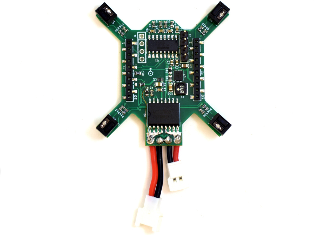
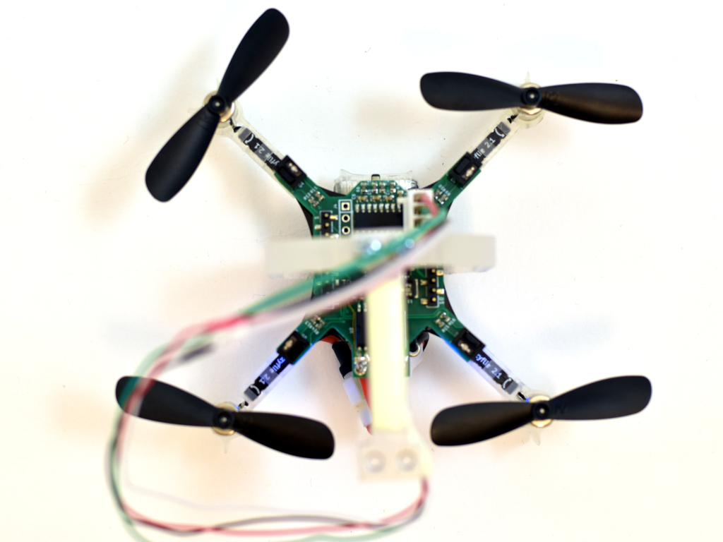
Previously we have been using off the shelf scales and other methods to measure characteristics, such as thrust or efficiency, of the Crazyflie products. We thought it was time to build something that is easier to use, more repeatable and tailored to our needs. Well, this has been on our wanted list for a long time, already back from when we did the RPM-deck. It was however first when Wolfgang visited us this winter that he nudged us over the edge so we finally allocated some time for it. We started off by buying some load cells and breakout boards to do something simple as a start, so we could at least measure thrust more easily. We actually started looking for off the shelf thrust stands but could not find anything suitable for the Crazyflie’s size. As is often the case here at Bitcraze, the project grew. Already before we had any load cells up and running I was designing a deck with RPM sensors, load cell amplifier and power meter. Now with the objective to easily do system identification. Therefor we named the deck the system-id deck.
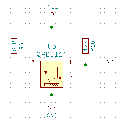
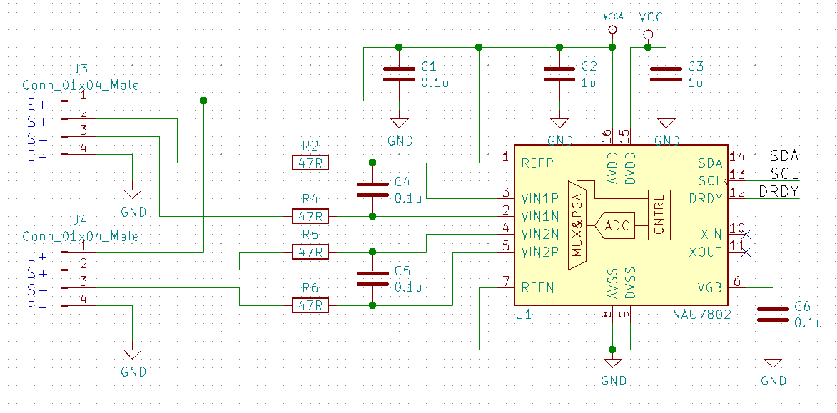
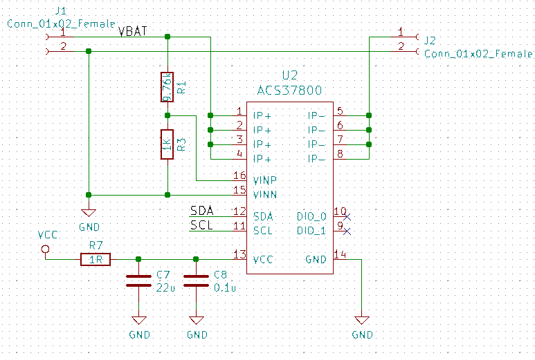
For the RPM sensors we used the same as on the RPM-deck, the QRD1114. They are not great as they need a reflective surface, this means adding white stickers or paint to black propellers, but they work well enough. The load cell amplifiers ended up to be the NAU7802 as it has a high accuracy and sample rate. For power metering we chose the new ACS37800 power monitoring IC that can handle up to 30A, this looked exiting.
The QRD1114 we wired the same way as previously done on the RPM-deck:
The NAU7802 was configured as per the datasheet suggestion and similarly to other open designs out there:
The ACS37800 was very new so the datasheet had to be used as the main information source. A bit tricky as this chip is mainly intended to measure mains supply, and we wanted to measure low voltage DC, which it said it could do…and in the end we managed to get it working.
We also added a buck/boost DC/DC that could provide a stable 3.3V from 2-5V input, just in case, as the ACS37800 is specified for this voltage and not the 3.0V the Crazyflie can supply.
The outcome
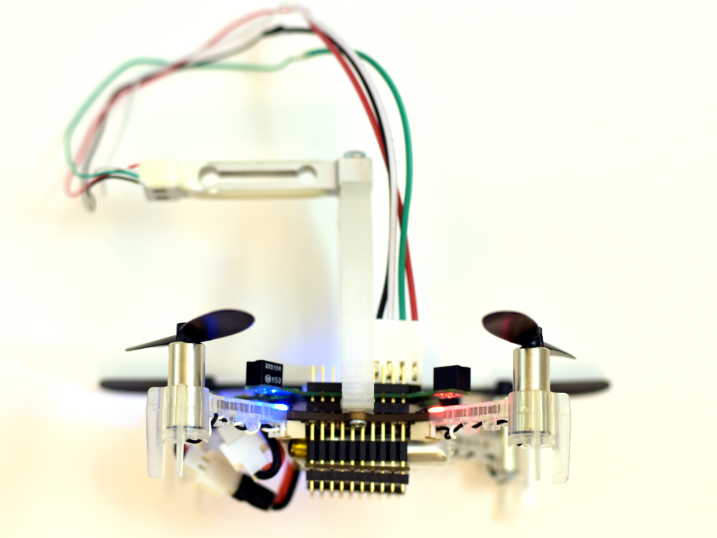
The PCB was designed as small as possible so it could be mounted on a Crazyflie 2.X and used while flying. A bonus would be if it could be used on a Bolt as well.
Here it is mounted on a Crazyflie 2.1 together with a 3D printed stand and load cell.
The load cell would then be mounted to a desk or similar so the the Crazyflie is mounted up-side down, pushing down on the load cell.
Software
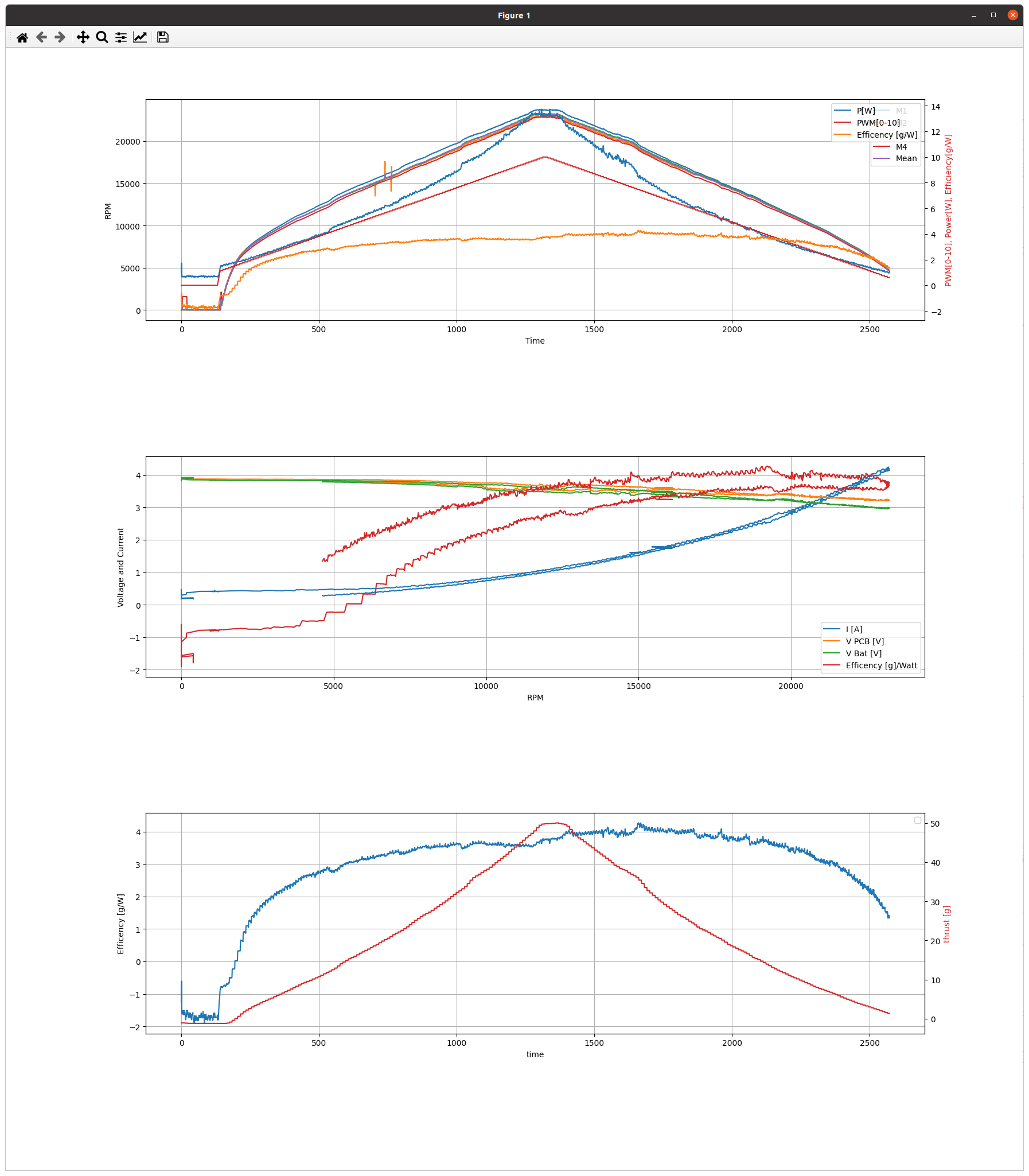
The software, as often, took most of the time to make. Three major deck driver files was created, rpm.c, acs37800.c and loadcell_nau7802.c. Aside from these there where only small changes to make, like making it work when being up-side-down. The modifications have all been pushed to the dev-systemid branch for those that are interested. As for now we are mainly using the logging framework to transfer the data to the PC, which is quick and easy to setup and use, but writing to SD-card is also possible. The scripts for this can be found in the tools/sytem_id folder.
Remaining work is to test, gather and analyse more data. When we have done so, we will post more. Until then below is a sample of what it can measure. The data is taken with a ramping PWM from 0% – 100% – 0%. The added resistance of the extra wires and connectors are not taken into account, but the estimated efficiency of 4g/W is probably not that far off.
We like to describe the Crazyflie as a versatile open source flying development platform. It is something that enables you to do cool stuff. It is not a finished, polished end product in its own.
This approach makes determining the expectations and requirements for the platform and the surrounding ecosystem a bit tricky. It is dependent on what you as a user plan to create using our products. And since the ecosystem is growing we need a, scalable, way to handle these fuzzy expectations during development and maintenance.
We think testing is big part of solving this, testing in a systematic, scalable and reproducible way. This is the reason for setting up our first physical test lab, aimed at providing stability while moving forward with new products and features.
Testing today
Continuous integration
On each change proposal to our software we run tests. For the firmware in the device we build multiple different configuration and run unit-tests. For the Crazyflie client and the Python library we make sure we can build for Linux and Windows and that the code passes our style guidelines. If any test fail we go back and update the proposed changed and re-run the tests. This is our first level of defense against defects.
Release testing
For each release we follow a checklist of procedures and tests to make sure that quality does not degrade. We make sure all the examples in the Python library are working and that the Crazyflie can fly around as expected in our flight arena, using various positioning systems.
Limitations
The way we test today makes it very difficult to determine if we regress in, for example, flight capability or in radio communication quality. We either test different software packages in isolation, without hardware in the loop, or we test by having a human trying to estimate if any degradation has happened since the last release.
We run into scalability issues as our ecosystem grows, it is near impossible to test all the different combinations of products. And it is very hard for us to detect stability or quality regressions without having a more systematic approach to testing the software on relevant hardware.
Introducing the test lab
What we have done so far are two things:
Created an infrastructure for setting up a site for testing our software on real devices
Prepared a test lab in our printer room at our office in Malmö
This new Git repository contains the building blocks we need to setup our new test lab. You can check out the repository README.md file for information on how to run it.
The repository contains a way to specify a test site, which is a collection of devices to run the test suite against. You specify your site in a TOML file which contain information about each device, such as which decks are connected and the radio:// URI. This site specification is then used by the test framework when running the tests, making sure each test is run against all devices compatible with that test.
The infrastructure also has management scripts to perform tasks like flashing all devices in a site, or recovering them if they go into boot loader mode by accident. All aimed at being able to handle testing with the least amount of human intervention possible.
This acts as a safety net for us. We will quickly know if the communication performance degrades, or if we have messed up with our parameter or logging frameworks. And we can catch silly firmware bugs as early as possible.
Future
We want to keep adding test cases and other infrastructure to our testing framework. Going forward it would be really nice to be able to test positioning systems in some way. And of course, some type of test of flight, be it free flying tests or using some kind of harness.
It might be interesting to look into adding simulations (hardware in loop or not) to our testing setup. It is all a question of bandwidth, there are a lot of cool things to work on, and a limit on time and bodies.
You can help! You might even be able to help yourself while helping us! If you contribute tests that correspond to your use-case, then you can relax knowing that those tests will run each night, and that Bitcraze engineers will be notified the minute they fail.
Or you can define your own site and run the test-suite against all your devices to make sure nothing strange is going on.
Hopefully this infrastructure and lab will help all of us to do more cool stuff using the Bitcraze ecosystem!
This week we have a guest blog post from Bart Duisterhof and Prof. Guido de Croon from the MAVlab, Faculty of Aerospace Engineering from the Delft University of Technology. Enjoy!
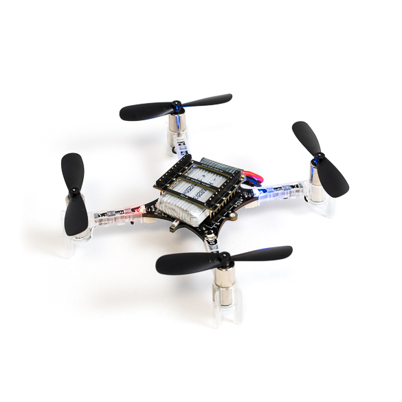
Tiny drones are ideal candidates for fully autonomous jobs that are too dangerous or time-consuming for humans. A commonly shared dream would be to have swarms of such drones help in search-and-rescue scenarios, for instance to localize gas leaks without endangering human lives. Drones like the CrazyFlie are ideal for such tasks, since they are small enough to navigate in narrow spaces, safe, agile, and very inexpensive. However, their small footprint also makes the design of an autonomous swarm extremely challenging, both from a software and hardware perspective.
From a software perspective, it is really challenging to come up with an algorithm capable of autonomous and collaborative navigation within such tight resource constraints. State-of-the-art solutions like SLAM require too much memory and processing power. A promising line of work is to use bug algorithms [1], which can be implemented as computationally efficient finite state machines (FSMs), and can navigate around obstacles without requiring a map.
A downside of using FSMs is that the resulting behavior can be very sensitive to their hyperparameters, and therefore may not generalize outside of the tested environments. This is especially true for the problem of gas source localization (GSL), as wind conditions and obstacle configurations drastically change the problem. In this blog post, we show how we tackled the complex problem of swarm GSL in cluttered environments by using a simple bug algorithm with evolved parameters, and then tested it onboard a fully autonomous swarm of CrazyFlies. We will focus on the problems that were encountered along the way, and the design choices we made as a result. At the end of this post, we will also add a short discussion about the future of nano drones.
Why gas source localization?
Overall we are interested in finding novel ways to enable autonomy on constrained devices, like CrazyFlies. Two years ago, we showed that a swarm of CrazyFlie drones was able to explore unknown, cluttered environments and come back to the base station. Since then, we have been working on an even more complex task: using such a swarm for Gas Source Localization (GSL).
There has been a lot of research focussing on autonomous GSL in robotics, since it is an important but very hard problem. The difficulty of the task comes from the complexity of how odor can spread in an environment. In an empty room without wind, a gas will slowly diffuse from the source. This can allow a robot to find it by moving up gradient, just like small bacteria like E. Coli do. However, if the environment becomes larger with many obstacles and walls, and wind comes into play, the spreading of gas is much less regular. Large parts of the environment may have no gas or wind at all, while at the same time there may be pockets of gas away from the source. Moreover, chemical sensors for robots are much less capable than the smelling organs of animals. Available chemical sensors for robots are typically less sensitive, noisier, and much slower.
Due to these difficulties, most work in the GSL field has focused on a single robot that has to find a gas source in environments that are relatively small and without obstacles. Relatively recently, there have been studies in which groups of robots solve this task in a collaborative fashion, for example with Particle Swarm Optimization (PSO). This allows robots to find the source and escape local maxima when present. Until now this concept has been shown in simulation [2] and on large outdoor drones equipped with LiDAR and GPS [3], but never before on tiny drones in complex, GPS-denied, indoor environments.
Required Infrastructure
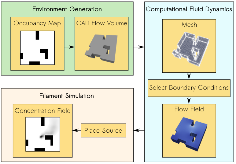
In our project, we introduce a new bug algorithm, Sniffy Bug, which uses PSO for gas source localization. In order to tune the FSM of Sniffy Bug, we used an artificial evolution. For time reasons, evolution typically takes place in simulation. However, early in the project, we realized that this would be a challenge, as no end-to-end gas modeling pipeline existed yet. It is important to have an easy-to-use pipeline that does not require any aerodynamics domain knowledge, such that as many researchers as possible can generate environments to test their algorithms. It would also make it easier to compare contributions and to better understand in which conditions certain algorithms work or don’t work. The GADEN ROS package [4] is a great open-source tool for modeling gas distribution when you have an environment and flow field, but for our objective, we needed a fully automated tool that could generate a great variety of random environments on-demand with just a few parameters. Below is an overview of our simulation pipeline: AutoGDM.
AutoGDM, a fully automated gas dispersion modeling (GDM) simulation pipeline.
First, we use a procedural environment generator proposed in [5] to generate random walls and obstacles inside of the environment. An important next step is to generate a 3D flowfield by means of computational fluid dynamics (CFD). A hard requirement for us was that AutoGDM needed to be free to use, so we chose to use the open-source CFD tool OpenFOAM. It’s used for cutting-edge aerodynamics research, and also the tool suggested by the authors of GADEN. Usually, using OpenFOAM isn’t trivial, as a large number of parameters need to be selected that require field expertise, resulting in a complicated process. Next, we integrate GADEN into our pipeline, to go from environment definition (CAD files) and a flow field to a gas concentration field. Other parts that needed to be automated were the random selection of boundary conditions, which has a large impact on the actual flow field, and source placement, which has an equally large impact on the concentration field.
After we built this pipeline, we started looking for a robot simulator to couple it to. Since we weren’t planning on using a camera, our main requirement was for the simulator to be efficient (preferably in 2D) so that evolutions would take relatively little time. We decided to use Swarmulator [6], a lightweight C++ robot simulator designed for swarming and we plugged in our gas data.
Algorithm Design
Roughly speaking, we considered two categories of algorithms for controlling the drones: 1) a neural network, and 2) an FSM that included PSO, with evolved parameters. Since we used a tiny neural network for light seeking with a CrazyFlie in our previous work, we first evolved neural networks in simulation. One of the first experiments is shown below.
A single agent in simulation seeking a light source using a tiny neural network.
While it worked pretty well in simple environments with few obstacles, it seemed challenging to make this work in real life with complex obstacles and multiple agents that need to collaborate. Given the time constraints of the project, we have opted for evolving the FSM. This also facilitated crossing the reality gap, as the simulated evolution could build on basic behaviors that we developed and validated on the real platform, including obstacle avoidance with four tiny laser rangers, while communicating with and avoiding other drones. An additional advantage of PSO with respect to the reality gap is that it only needs gas concentration and no gradient of the gas concentration or wind direction (which many algorithms in literature use). On a real robot at this scale, estimating the gas concentration gradient or the direction of a light breeze is hard if not impossible.
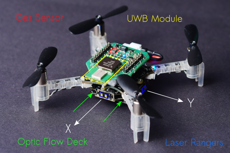
Hardware
Our CrazyFlie needs to be able to avoid obstacles, execute velocity commands, sense gas, and estimate the other agent’s position in its own frame. For navigation, we added the flow deck and laser rangers, whereas for gas sensing we used a TGS8100 gas sensor that was used on a CrazyFlie before in previous work [7]. The sensor is lightweight and inexpensive, but accurately estimating gas concentrations can be difficult because of its size. It tends to drift and needs time to recover after a spike in concentration is observed. Another thing we noticed is that it is possible to break them, a crash can definitely destroy the sensor.
To estimate the relative position between agents, we use a Decawave Ultra-Wideband (UWB) module and communicate states, as proposed in [8]. We also use the UWB module to communicate gas information between agents and collaboratively seek the source. The complete configuration is visible below.
A 37.5 g nano quadcopter, capable of fully autonomous waypoint tracking, obstacle avoidance, relative localization, communication and gas sensing.
Evaluation in Simulation
After we optimized the parameters of our model using Swarmulator and AutoGDM, and of course trying many different versions of our algorithm, we ended up with the final Sniffy Bug algorithm. Below is a video that shows evolved Sniffy Bug evaluated in six different environments. The red dots are an agent’s personal target waypoint, whereas the yellow dot is the best-known position for the swarm.
Sniffy Bug evaluated in Swarmulator environments.
Simulation showed that Sniffy Bug is effective at locating the gas source in randomly generated environments. The drones successfully collaborate by means of PSO.
Real Flight Testing
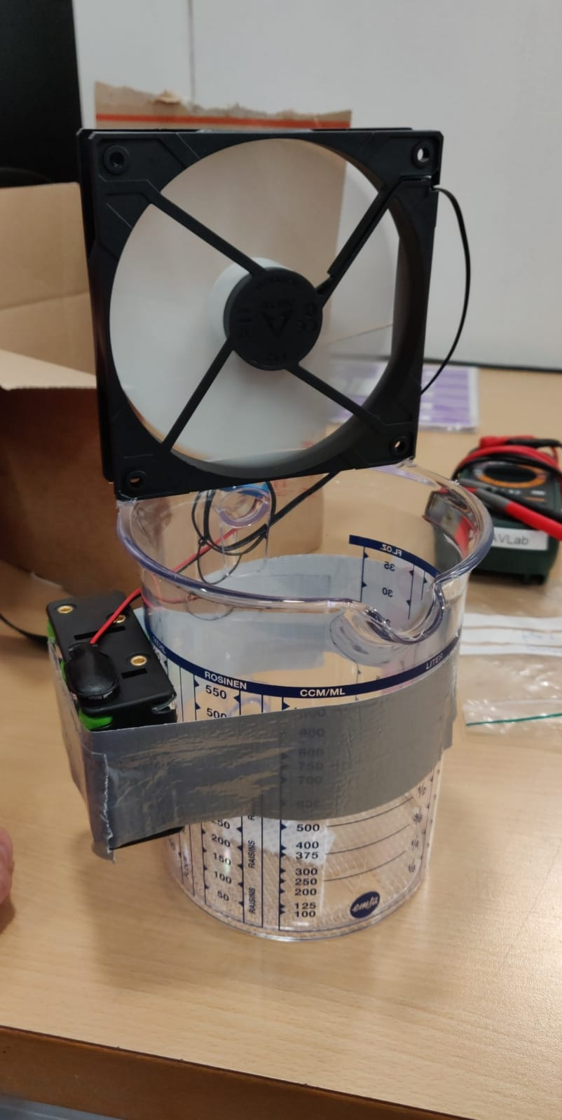
After observing Sniffy Bug in simulation we were optimistic, but unsure about performance in real life. First, inspired by previous works, we disperse alcohol through the air by placing liquid alcohol into a can which is then dispersed using a computer fan.
Dispersion of liquid alcohol in flight tests.
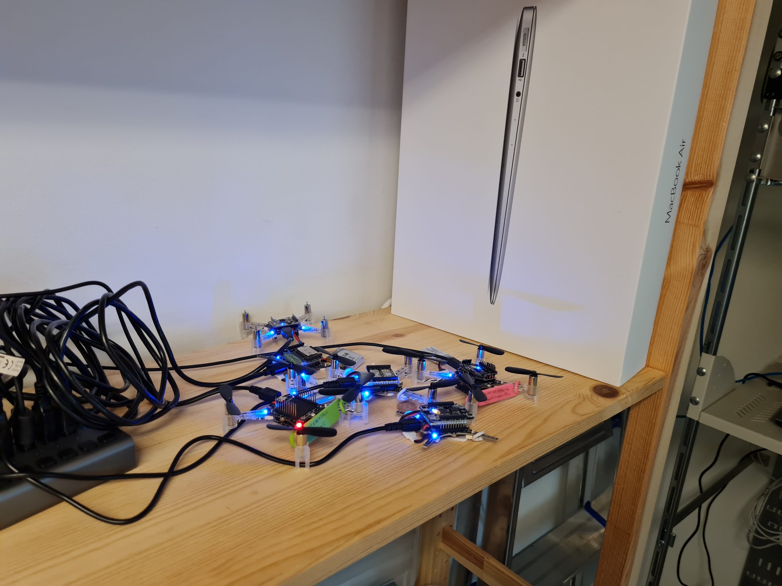
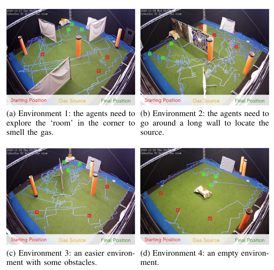
We test Sniffy Bug in our flight arena of size 10 x 10 meters with large obstacles that are shaped like walls and orange poles. The image below shows four flight tests of Sniffy Bug in cluttered environments, flying fully autonomously, i.e., without the help from any external infrastructure.
Time-lapse images of real-world experiments in our flight arena. Sniffy was evaluated on four distinct environments, 10 x 10 meters in size, seeking a real isopropyl alcohol source. The trajectories of the nano quadcopters are clearly visible due to their blue lights.
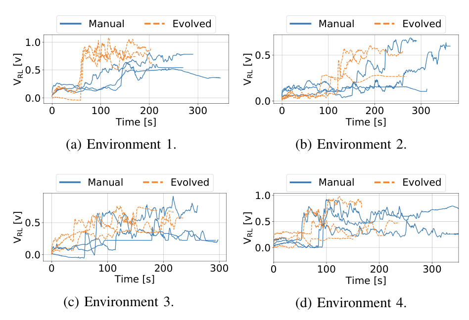
In the total of 24 runs we executed, we compared Sniffy Bug with manually selected and evolved parameters. The figure below shows that the evolved parameters are more efficient in locating the source as compared to the manual parameters.
Maximum recorded gas reading by the swarm, for each time step for each run.
This does not only show that our system can successfully locate a gas source in challenging environments, but it also demonstrates the usefulness of the simulation pipeline. The parameters that were learned in simulation yield a high-performance model, validating the environment generation, randomization, and gas modeling parts of our pipeline.
Conclusion and Discussion
With this work, we believe we have made an important step towards swarms of gas-seeking drones. The proposed solution is shown to work in real flight tests with obstacles, and without any external systems to help in localization or communication. We believe this methodology can be extended to larger environments or even to 3 dimensions, since PSO is a robust, multi-dimensional heuristic search method. Moreover, we hope that AutoGDM will help the community to better compare gas seeking algorithms, and to more easily learn parameters or models in simulation, and deploy them in the real world.
To improve Sniffy Bug’s performance, adding more laser rangers will definitely help. When working with only four laser rangers you realize how little information it actually provides. If one of the rangers senses a low value it is unclear if a slim pole or a massive wall is detected, adding inefficiency to the algorithm. Adding more laser rangers or using other sensor modalities like vision will help to avoid also more complex obstacles than walls and poles in a reliable manner.
Another interesting discussion can be held on the hardware required for real deployment. When working with 40 grams of maximum take-off weight, the sensors and actuators that can be selected are limited. For example, the low-power and lightweight flow deck works great but fails in low-light scenarios or with smoke. Future work exploring novel sensors for highly constrained nano robots could really help increase the Technological Readiness Level (TRL) of these systems.
Finally, this has been a really fun project to work on for us and we can’t wait to hear your thoughts on Sniffy Bug!
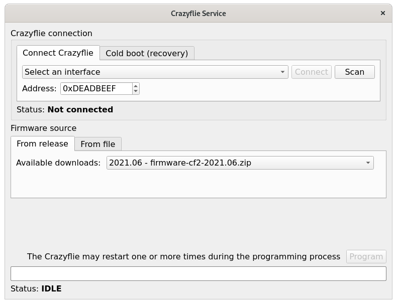
We are happy to announce the availability of the 2021.06 release of the Crazyflie firmware and client! This release includes bugfixes related to flashing the Crazyflie and the Lighthouse deck and also the new concept of core parameters and logging variables, that we talked about in the blog post: Crazyflie logging and parameters interface.
We always strive to release quality software and firmware, but we are not perfect! Please help us out by installing the new library, client and firmware and make sure that your applications, tools and algorithms still work as you expect! And if not please file an issue with us or contact us via the forum.