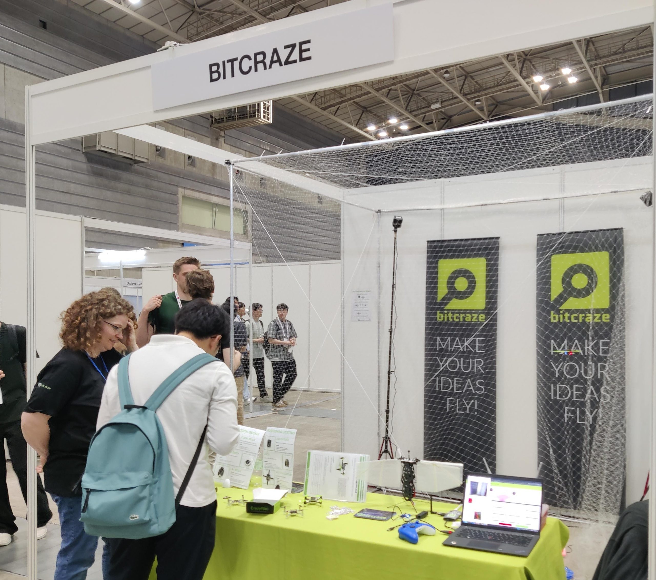
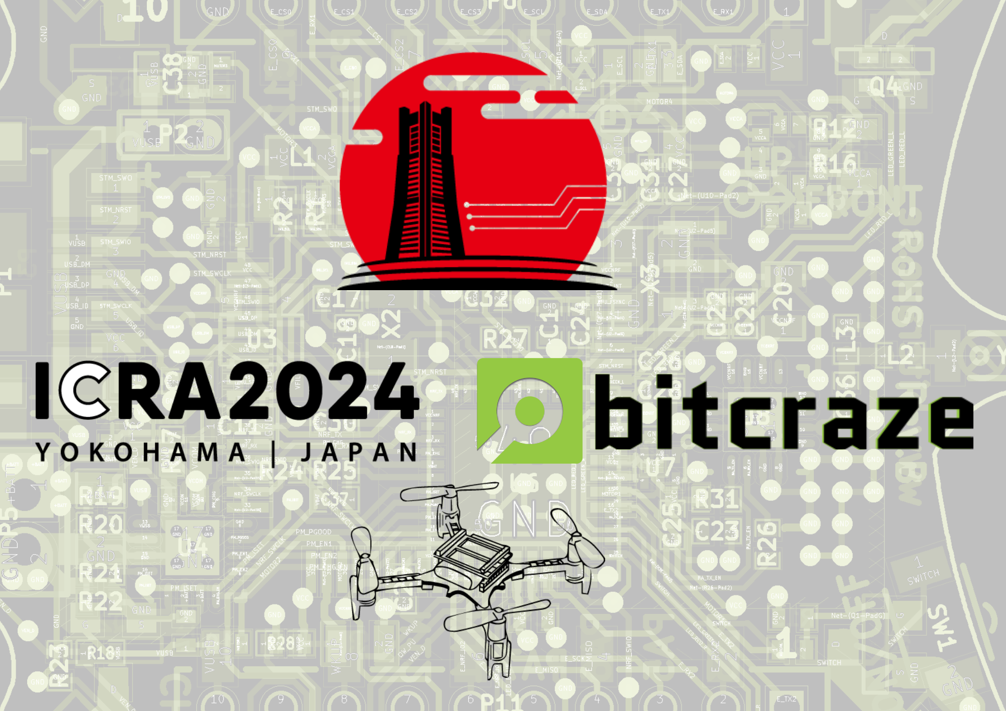
Two weeks ago, Arnaud, Barbara and Rik were at ICRA 2024 in Yokohama. At our booth we showed our current products as well as the upcoming brushless Crazyflie and the camera deck prototype.
As usual, the conference has been very busy with a lot of visitors and a lot of very interesting discussion. Thanks to everyone that passed by the booth, we have come back to Sweden with a lot of energy and new ideas!
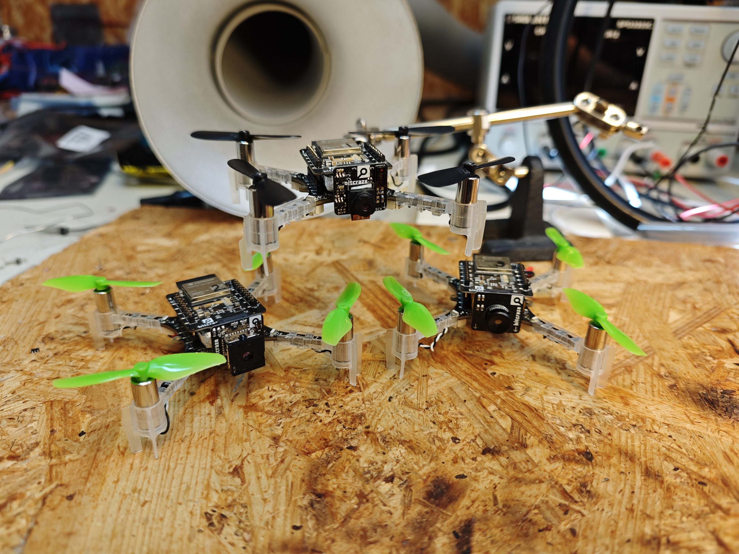
The autonomous lighthouse swarm demo demo has worked pretty well. If you are interested to know more about it you can visit our event page. It is an autonomous demo with 3 brushless Crazyflies and 6 Crazyflie 2.1s flying autonomously. With the extended battery life of the brushless, we could operate the demo pretty much continuously.
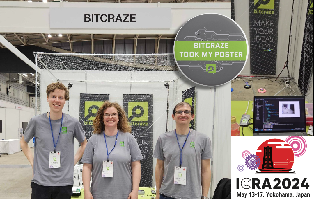
If you’ve been at the conference, you may have spotted someone proudly sporting our exclusive ‘Bitcraze took my poster’ button. We’re excited to have received posters covering a wide range of topics, the walls of our office are eagerly awaiting these visual representations of your hard work and dedication. Thank you to everyone who has contributed.
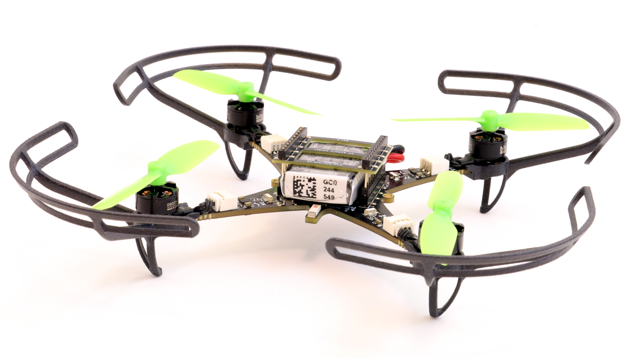
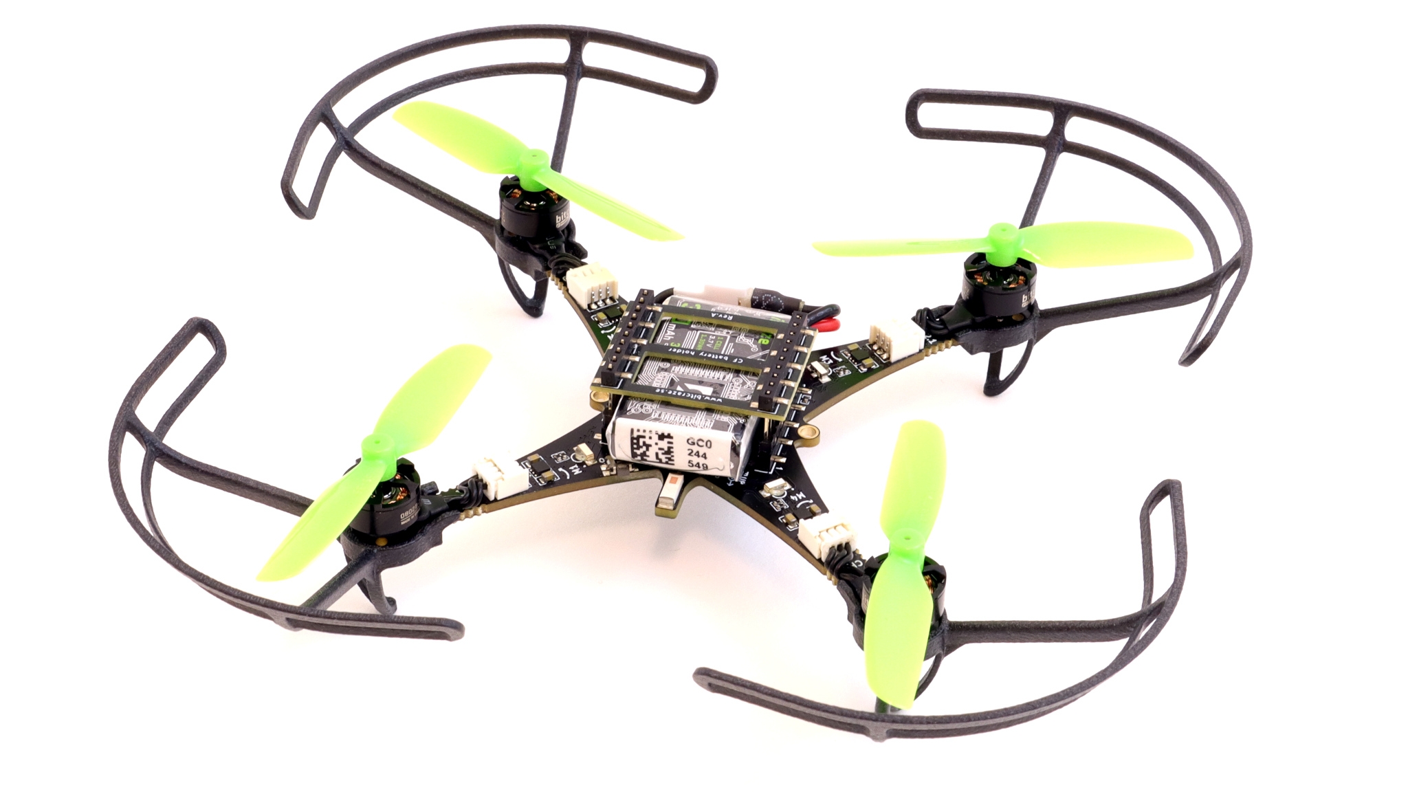
One of the great features of the stock Crazyflie 2.1 is that it is more or less harmless. The Crazyflie 2.1 brushless weighs roughly the same but has almost twice the amount of thrust force, so a little bit of more care is needed. We therefore decided to provide optional propeller guards. While propeller guards adds safety they also add weight and disrupt the air flow from the propellers. Adding to that, the weight is located far from the center which increases the inertia even further, resulting in a less agile drone. For some applications this is not a problem but for others it is, this is why we are making them optional, meaning they are easy to replace with simple landing legs by utilizing a snap-on fitting.
The design is not fully finalized yet but we are getting close, voilá!
If the design goes according to plan they will also withstand some bumping against walls which will be a very nice feature for many applications.
Further the landing legs and propeller guards are designed in a way so they will detach during high force impacts to prevent the PCB arms from breaking.
“What? You are in Japan? Again!?”. Yup that is right! We loved IROS Kyoto 2022 so much that we just couldn’t wait to come back again. Barbara, Arnaud and Rik are setting up the booth as we speak to show some Bitcraze awesomeness to you! Come and say hi at booth IC085.
The gang before the rush starts!
Crazyflie Brushless and Camera expansion
Of all the prototypes we are the most excited of showing you the Crazyflie Brushless and the ‘forward facing expansion connector prototype’ aka the Camera deck. Here you can see them both in action at a tryout of our demo. We have also written blogposts about both so make sure to read them as well (Brushless blogpost, Camera expansion blogpost)
The Crazyflie Brushless flying with a Camera deck.
Also we will explain about the contact charging prototype (see the blogpost here) and will be showing all of our decks at the booth as well. And of course our fully autonomous, onboard, decentralized peer-to-peer and avoiding swarm demo will be displayed as always. Make sure to read this blogpost of when we showed this demo at IROS 2022 to understand what is fully going on!
We will be providing a ‘special disposal service’ for your conference poster! We would love to see what you are working on and get your poster, because we have a lot of space in our updated office/flight space but a lot of empty walls.
If you hand in your poster at the booth, you’ll get a special, one-of-a-kind, button badge that you can wear proudly during the conference! So we will see you at booth IC085!
My name is Joseph La Delfa, I started in December last year as an industrial postdoc at Bitcraze. This means I work across Bitcraze HQ in Malmö and the division of Robotics Perception and Learning at KTH in Stockholm. I have been designing and researching interactions that involve bodily control of drones for a few years now.
In order of appearance: Demonstrating at a conference, mucking around with the Qualisys tab, coaching at Drone Arena I, playing judge at Drone Arena II, and finally Drone Chi.
Here at Bitcraze I will be using lighthouse decks on the body to control Crazyflie/s, with the aim to produce a wearable sensor that integrates into the Bitcraze ecosystem. The lighthouse positioning system is showing great potential for this application as it gives relatively clean and high-fidelity positional data. Plus now that more than two base stations can be used, we can potentially track the deck from top down and bottom up.
Three motor-less crazyflies are strapped to my arms and tracked using two lighthouse basestations.
This research is a continuation of my PhD thesis, where I designed drone interactions that respond differently to different people, and advocated for a human-drone relationship that evolves over time. Ultimately I hope to demonstrate new use cases for the Crazyflie and expand the already impressive community of researchers who use Bitcraze products!
How to Train Your Drone was a one-month field study in a shared home, where three housemates taught their drones how to fly.
This industrial postdoc is funded by the Wallenberg AI, Autonomous Systems and Software Program (WASP), and you can find out more about my work at www.cafeciaojoe.com :D
A great feature of the Crazyflie is its ability to keep evolving, both by using software but also through hardware expansions. Hardware expansions allow us and our users to keep exploring new problems and doing new experiments, without having to change the flying base. Over the years lots of new decks have been released and we’ve seen lots of users building their own custom electronics and attaching it to their Crazyflies. Although very versatile, the current deck system is limited to up/downwards facing expansions. Adding electronics that face forward, like a camera, has been harder and has required additional mechanics. Over the last couple of months we’ve been experimenting with a new expansion connector aiming at solving this issue. The idea is to be able to add a new class of expansions facing forward. This week’s blog post and next week’s developer meeting are about these experiments.
Goals and design
We’re always trying to find ways to make our platform more versatile, making it easier to expand and to be used in new ways. So we’ve been looking for a new way to be able to expand the platform even more, this time with electronics facing forward instead of up/down. The goal is to easily be able to add things such as cameras, ranging sensors etc. Making a custom deck with custom mechanics for each sensor hasn’t been a good solution, it takes lots of time and it doesn’t enable our users to do their own custom electronics. Finding a generic solution is hard since we’re constrained both in space and in weight. We need a solution which is very small and light, each gram adding cuts into the flight time. The solution also needs a way to handle the data generated from cameras/sensors as well as possibly to stream it over a faster connection than the Crazyradio.
Our current prototype is made of two parts, a new deck with WiFi and more computational power as well as several smaller expansions which can be added to it. The expansions fit straight into a small right angle connector, making it easy to change boards. The current connector we’re testing has 30 positions, of which 6 is used for power and 1 for 1-wire, leaving 24 pins for signaling. The 1-wire works the same way as our current decks, additional added hardware is auto-detected at startup and can be used without recompiling or reconfiguration.
The current prototype uses an ESP32-S3 and weighs in at 3.7 grams. Added to this there are a number of expansions that we’re evaluating:
OV2640 + VL53L5CX: RGB camera and ranging sensor (1.6 grams)
Flir Lepton 3.5: Thermal camera (2.1 grams)
MLX90640: Thermal camera (2.0 grams)
So the current prototype with RGB camera (and ranging sensor) weights in at a total of 5.3 grams (0.9 grams more than the AI deck).
Current status and continuation
We’re currently experimenting with connectors, modules and dimensions. In the coming months we will try to get more flight time to test the solution and we’re hoping to get some feedback from our users. So please post any comments and/or suggestions you might have.
If you’re interested in knowing more and discussing this then join our developer meeting next week on Wednesday. We will also be showing off the prototypes at ICRA, so make sure to swing by the booth if you’re attending.
From the beginning of the company, we’ve always loved to join in at conferences. Only at a conference do you get the opportunity to show our products, meet our users or other tech-oriented people, learn about what others are doing, and let’s not forget the chance to discover a new place!
This year, we’ll be present at ICRA Yokohama – it’s in just 3 weeks. We’ll have a booth there (IC085 if you’re looking for us). We’ll be showing our autonomous demo with a twist just like we have shown last time, so please check the event page. This demo is extremely impressive and we’ve been improving on it each time we’ve shown it – beginning in our latest Japan trip and lastly at the last ICRA too. What’s new?
… and perhaps some more prototypes of whatever we managed to bring in our suitcase!
We’re really excited to be showing that and receive feedback, but also in hearing about what our users have been doing. ICRA is always a perfect place to catch up on all the amazing papers and publications featuring our hardware, and we couldn’t be prouder of all the cool stuff we’ve seen so far. We’re so proud, in fact, that we want to be able to show off! So, if you have a paper or a publication featured at ICRA, let us know – you can write us an email at contact@bitcraze.io, leave a comment below this post, or pass by our booth.
In fact, we’re prepared to make a deal. If you have a nice poster featuring our products and don’t know what to do with it once you’ve presented it, pass by our booth! We’re ready to swap them for something extra special. We plan to have a “hall of fame” at the office featuring your awesome work – in fact, it’s an idea we had last ICRA when someone just offered us their posters. Now, we’d like to cover our walls with them!
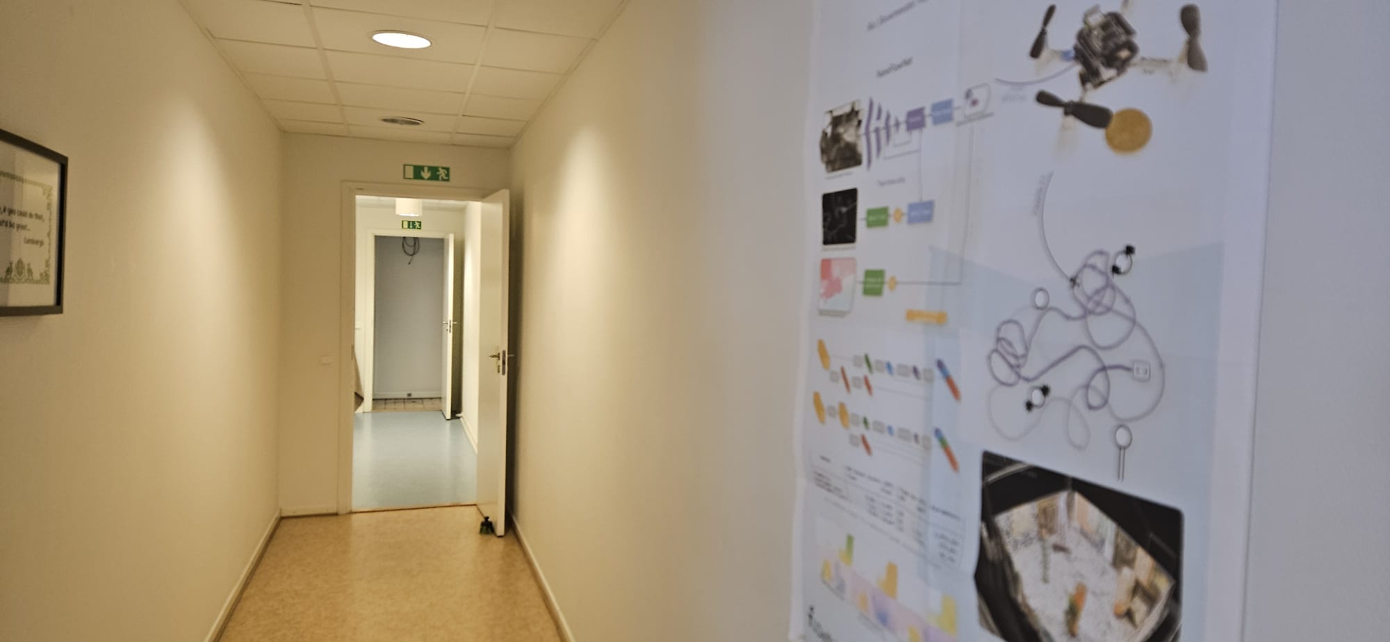
The corridor leading to the kitchen – we have space to show off the awesomeness!
So, whether you’re a seasoned conference-goer or a first-time attendee, don’t hesitate to wsing by our booth, say hello, and discover our newest demo! We hope to see you there.
Dev meeting
Next developer meeting is going to be on the 8th of May – we traditionally have a dev meeting every first Wednesday of the month, but this time it happens to be on the 1st of May which is a holiday here in Sweden. So already prepare your calendar for the 8th of May at 15.00 CET, and stay tuned for more info on which topic we’ll talk about!
Crazyflies back in stock !
You may have noticed that the Crazyflies have been out of stock for some time now. After some adventures, we are now fully back in stock with most of our bundles and products available in the shop!
Simulators are one of the most important tools used in robotics research. They usually are designed for different purposes with different levels of complexity. For example, simulators with low computational overhead that are parallelizable are mainly used for either training reinforcement learning algorithms or Monte Carlo sampling for verification of task completion in a nondeterministic environment. Some simulators also use rendering engines for the graphical display of models and the environment or when cameras are intended to be used in the robotics platform. Simulation is also useful for the development and deployment of new robotics firmware features where the firmware is compiled on a test machine and run in the loop with a simulated sensor suite. This simulator configuration is known as software-in-the-loop (SITL) because the vehicle firmware is intended to be run in the loop with the simulated vehicle physics and/or rendering engine. This feature is supported by autopilot suites such as PX4, ArduPilot, CogniPilot, and BetaFlight. This feature is not officially supported yet for Crazyflies because it requires a large overhaul of the firmware to be able to compile on a desktop machine and interact with different simulators such as Gazebo, Webots, PyBullet, CoppeliaSim, Isaac Sim, or Unreal Engine.
CrazySim
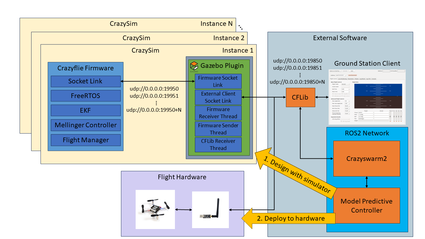
Last summer I began working with Crazyflies and noticed this Crazyflie simulator gap. I stumbled on a community-developed project for Crazyflie SITL called sim_cf. This project is exactly what I was looking for. However, the firmware used by the project is from July 2019 and the official firmware has had over 2000 commits made since then. The project also uses ROS 1, Gazebo Classic, and doesn’t support the Crazyflie Python library (CFLib). Using this project as a starting point I set out to develop CrazySim–a Crazyflie SITL project that doesn’t require ROS, uses Gazebo Sim, and supports connectivity through CFLib. Using CFLib we can connect the simulator to external software such as Crazyswarm2 or the Crazyflie ground station client. Users test their control algorithms in the external software using the simulator interface before deploying to real flight hardware.
An example of offboard model predictive control design and deployment workflow using CrazySim.
Using the Crazyflie Client for PID Tuning
We have also provided a modified Crazyflie client for CrazySim support. The Crazyflie client is a cool tool for testing a single drone in hardware. We can perform command based flight control, look at real time plots, save log data, and tune PID values in real time. The PID values are typically tuned for an out of the box Crazyflie. However, when we modify the Crazyflie and add extra weight through batteries, decks, and upgraded thrust motors then the behavior of the Crazyflie will change. If a user wants to tune a custom Crazyflie setup, then they can add additional models in this folder with their own motor and mass properties. Then they just need to add it to the list of supported models in either of the launch scripts. There is already an example model for the thrust upgrade bundle. Documentation for installing the custom client can be found here.
PID tuning a simulated Crazyflie using CrazySim on the Crazyflie PC client.
Crazyswarm2
We can now connect to the simulated Crazyflie firmware using CFLib. Therefore, we can set up a ROS 2 interface through Crazyswarm2 for swarm command and control through ROS 2 topics and services. To do this we first startup the drones using any of the launch scripts.
Then, we bring up Crazyswarm2 after setting up the configuration file for the number of drones chosen.
ros2 launch crazyflie launch.py backend:=cflib
We demonstrate an example of how we can control a swarm of drones using Crazyswarm2 GoTo service commands.
Crazyswarm2 GoTo service commands using CrazySim.
ICRA 2024
CrazySim is also being presented as a paper at the 2024 IEEE International Conference on Robotics and Automation in Yokohama, Japan. If you are attending this conference and are interested in this work, then I invite you to my presentation and let me know that you are coming from this blog post after. For the paper, I created a multi agent decentralized model predictive controller (MPC) case study on ROS 2 to demonstrate the CrazySim simulation to hardware deployment workflow. Simulating larger swarms with MPC may require a high performance computer. The simulations in this work were performed on an AMD Ryzen 9 5950X desktop processor.
Model predictive control case study for ICRA 2024 paper.
Hey folks! I’m Tove, and I’m thrilled to be part of the fantastic team at Bitcraze.
Bitcraze had me at “open source, self-organizing, and drones!”. The way of working, using modern software practices and the fact that the company isn’t a corporate behemoth but still packs a punch in innovation really spoke to me.
I come from the world of radio modules and Internet of Things (IOT), building software and customer applications at u-blox. u-blox is also where I wrote my thesis that wandered into indoor positioning territory, which is another reason why I was immediately drawn to Bitcraze once they entered my radar. I studied computer science with an emphasis on embedded systems at Malmö University.
When I’m not working with tech, you can find me playing board games, reading fantasy novels or working on silversmithing projects. I’m also a big fan of being out in nature, especially sailing, and even used to study environmental science before I switched over to ones and zeros.
I’m excited to learn about the great world of drones and robotics. I mean, who has not dreamt about that at some point in their life?! I’m a very poor drone flyer, but I guess some training in that department will help. I love working with tests and software quality to make sure everyone can feel comfortable and focus on developing new exciting features, while being sure nothing breaks in the process!
Looking forward to getting into the team and making things happen together!
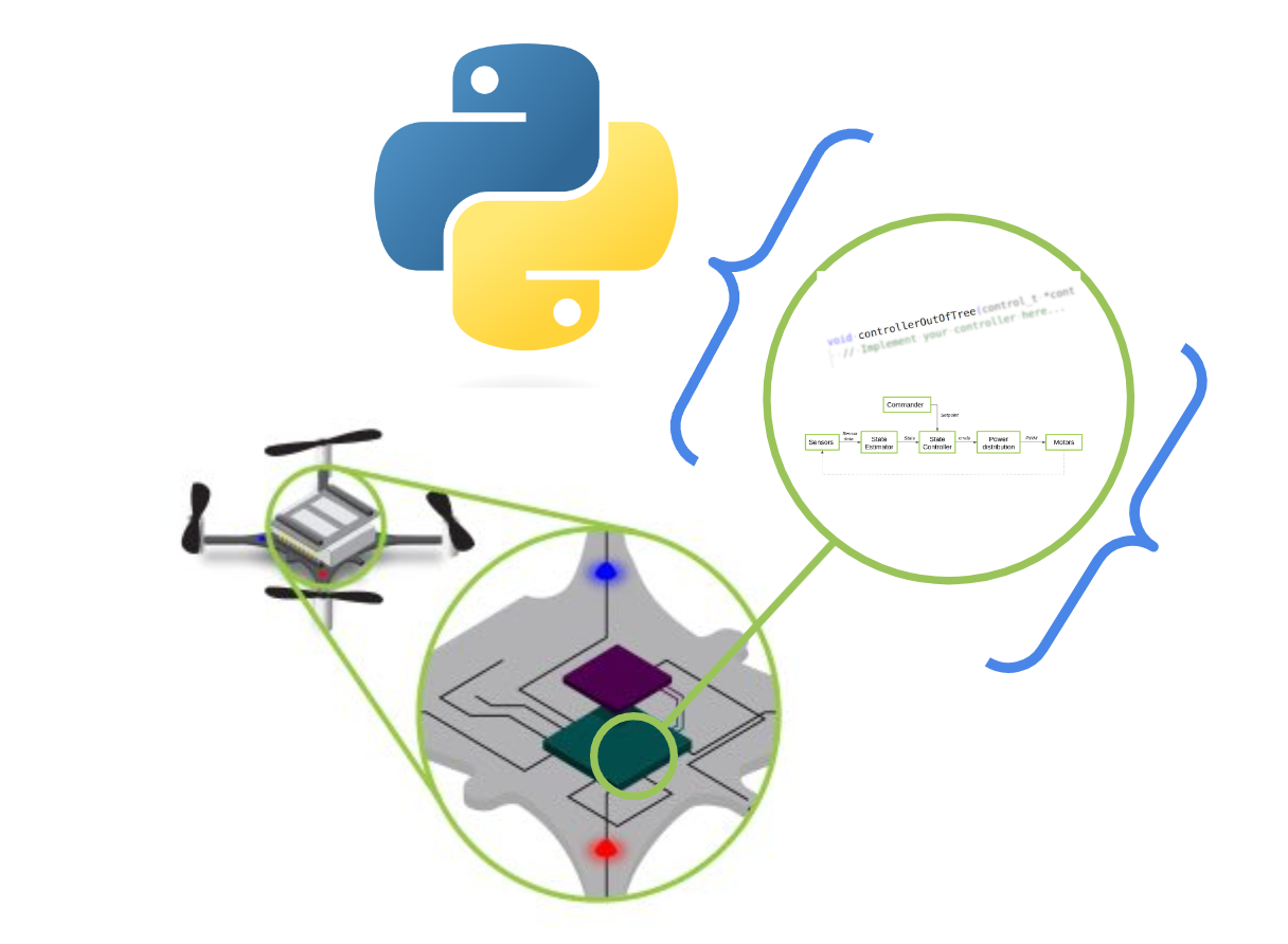
Today, we’d like to take the opportunity to spotlight a feature that’s been in our code base for some time, yet hasn’t been the subject of a blog post: the Python bindings for our Crazyflie firmware. You may have noticed it mentioned in previous blog posts, and now we’ll delve into more detail about what it is, how we and others are utilizing it, and what its future holds.
What are the Python bindings?
Language bindings, in essence, are libraries that encapsulate chunks of code, enabling one programming language to interface with another. For instance, consider the project Zenoh. Its core library is crafted in Rust, but it offers bindings/wrappings for numerous other languages like Python, C/C++, and so on. This allows Zenoh’s API to be utilized in scripts or executables written in those languages. This approach significantly broadens the functionality without necessitating the rewriting of code across multiple programs. A case in point from the realm of robotics is ROS(1), which initially created all of their APIs for different languages from scratch—a maintenance nightmare. To address this, for ROS 2, they developed the primary functionality entirely in C and provided wrappers for all other programming languages. This strategy eliminates the need to ‘reinvent the wheel’ with each iteration.
Rather than redeveloping the firmware in Python, our esteemed collaborators Wolfgang Hönig and James Preiss took a pragmatic approach. They selected parts of the Crazyflie firmware and wrapped them for Python use. You can see the process in this ticket. This was a crucial step for the simulation of the original Crazyswarm (ROS1) project and was continued for its use in the Crazyswarm2 project, which is based on ROS 2. They opted for SWIG, a tool specifically designed to wrap C or C++ programs for use with higher-level target languages. This includes not only Python, but also C#, GO, Javascript, and more, making it the clear choice for implementing those bindings at the time. We also strongly recommend checking out a previous blogpost by Simon D. Levy, who used Haskell to wrap the C-based Crazyflie Firmware for C++.
Where are the Python bindings being used?
As previously mentioned, the Crazyswarm1 & 2 projects heavily utilize Python bindings for testing key components of the firmware (such as the high-level commander, planner, and controller) and for a (hybrid) software-in-the-loop simulation. During the project’s installation, these Python bindings must be compiled so they can be used during simulation. This approach allows users to first test their trajectories in a simulated environment before deploying them on actual Crazyflies. The advantage is that minimal or no modifications are required to achieve the same results. While simulations do not perfectly mirror real-world conditions, they are beneficial because they operate with the same controller as the one used on the Crazyflie itself. In our own Crazyflie simulation in Webots, it’s also possible to use these same bindings in the simulator by following these instructions.
Three controllers (PID, Mellinger, and Brescianini), intra-drone collision avoidance, and the high-level commander planner have all been converted into Python bindings. Recently, we’ve added a new component: the Extended Kalman Filter (EKF). This addition is ideal as it allows us to test the filter with recorded data from a real Crazyflie and experiment with different measurement models. As we discussed in a previous blogpost, estimators are complex due to their dependence on chance and environmental factors. It’s beneficial for developers to have more control over the inputs and expected outputs. However, the EKF is deeply integrated into the interconnected processes within the Crazyflie Firmware. After a significant refactoring effort, these were added to the bindings by creating an EKF emulator (see this PR). This enabled Kristoffer to further enhance the TDOA outlier filter for the Crazyflie by emulating the full process of the EKF, including IMU data.
In addition to SITL simulation and EKF development, Python bindings are also invaluable for continuous integration. They enable comprehensive testing that encompasses not just isolated code snippets, but entire processes. For instance, if there’s a recording of a Crazyflie flight complete with sensor data (such as flow, height, and IMU data), and it’s supplemented with a recorded ground truth (from lighthouse/mocap), this sensor data can be fed into the EKF Python binding. We can then compare the outputted pose with the ground truth to verify accuracy. The same principle applies to the controllers. Consequently, if any changes are made to the firmware that affect these crucial aspects of Crazyflie flight, these tests can readily detect them.
If you like to try the python bindings tests for yourself, clone the Crazyflie-firmware repo and build/install the python bindings via these instructions. Make sure you are in the root of the repository and run: python3 -m pytest test_python/. Mind that you might need to put the bindings in the same path with export PYTHONPATH=<PATH_TO_>/crazyflie-firmware/build:$PYTHONPATH (please see this open ticket)
The next steps of the python bindings
We’ve seen how Python bindings have proven to be extremely useful, and we’re keen to further expand their application. At present, only the Loco positioning system has been incorporated into the EKF part of the Python bindings. Work is now underway to enable this for the Lighthouse system (see this draft PR). Incorporating the Lighthouse system will be somewhat more complex, but fortunately, much of the groundwork has already been laid, so we hope it won’t be too challenging. However, we have encountered issues when using the controller bindings with simulation (see this open ticket). It appears that some hardware-specific timing has been hardcoded throughout the PID controller in particular. Therefore, work needs to be done to separate the hardware abstraction from the code, necessitating additional refactoring work for the controller.
Recent projects like Sim_CF2 (see this blogpost) and Crazysim (see this discussion thread) have successfully compiled the Crazyflie firmware to run as a standalone node on a computer. This allows users to connect it to the Crazyflie Python library as if it were an actual Crazyflie. This full Software-In-The-Loop (SITL) functionality, already possible with autopilot suites like PX4 and Ardupilot, is something we at Bitcraze are eager to implement as well. However, considering the extensive work required by the aforementioned SITL projects to truly separate the hardware abstraction layer from the codebase, we anticipate that refactoring the entire firmware will be a substantial task. We’re excited to see what we can achieve in this area.
Indeed, even with a more comprehensive Software-In-The-Loop (SITL) solution, there’s no reason to completely abandon Python bindings. For developments requiring more input/output control—such as the creation of a new controller or an addition to the Extended Kalman Filter (EKF)—it’s beneficial to start with just that portion of the firmware code. Python bindings and a SITL build can coexist, each offering its own advantages and disadvantages for different stages of the development process. By leveraging the tools at our disposal, we can minimize the risk of damaging Crazyflies during development. Let’s continue to make the most of these valuable resources!
Dumping and loading persistent parameters to and from a file
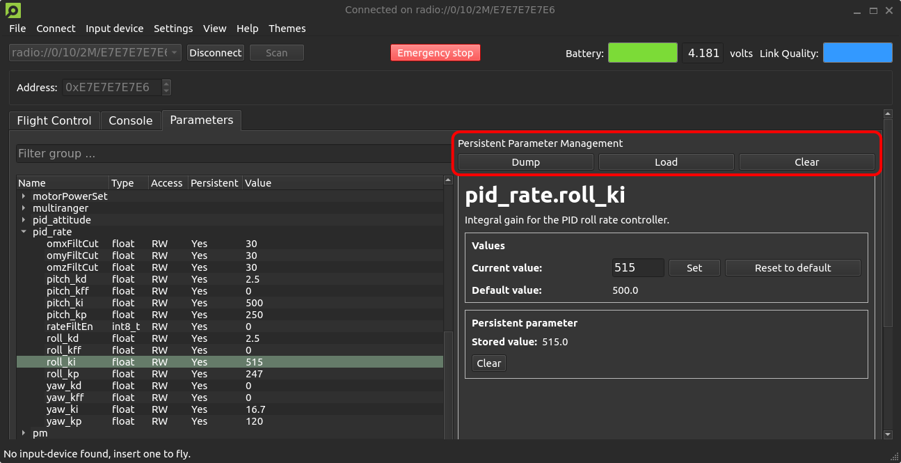
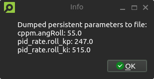
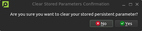
We have a small quality-of-life update that will allow users to dump and load persistent parameters to and from a file that has recently been merged #PR443 and #PR706. A new persistent parameter management area is introduced to the parameters tab of the client, with buttons for dumping and loading persistent parameters, as well as clearing all stored persistent parameters from the Crazyflie. The persistent parameters are stored in .yml format, allowing for manual editing if desired. If you have any improvement suggestions please drop us a comment!
A new persistent parameter management area is introduced to the parameters tab of the client, with buttons for dumping, loading and clearing stored persistent parameters.An information dialog notifies users of the dumped persistent parameters and their values. Loading parameters will result in a similar pop-up.A confirmation dialog prevents accidental clearing of persistent parameters.
System-id code merged to master
Back in 2021, we created the system-id deck which we talked about in this blog post. It has not been officially released but a few users have gotten some PCBs and built it themselves. The functionality for the system-id deck has previously been in a branch, but as code in branches tends to become outdated, we have now moved this into the master branch utilizing the kbuild system instead. Building for the system-id deck is now as easy as doing “make sysid_defconfig” and then compiling. While talking about the system-id deck, let’s check the interest of releasing it as a product. It can help with system identification, tuning of controllers, improving efficiency etc. With enough interest there might be an economy in manufacturing it.
Out of stock
Unfortunately, we’re out of stock of Crazyflies at the moment. We expect some at the end of next week, so hopefully, you should be able to find them back in the store quickly.
Developer meeting
The next developer meeting will be on the 6th of March 2024, Arnaud will talk about the Crazyflie Client past, present and future, based on its last blog post. The client is still very useful but starts to show its age so we are looking at what should be kept, what should be improved and what should be removed. We will present what we have in mind, please come and discuss with us so we can shape the next 10 years of Crazyflie client!