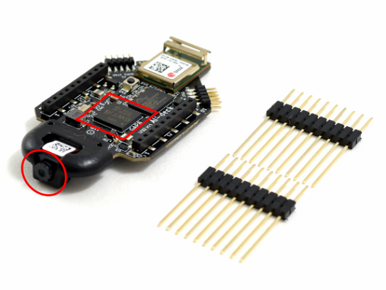
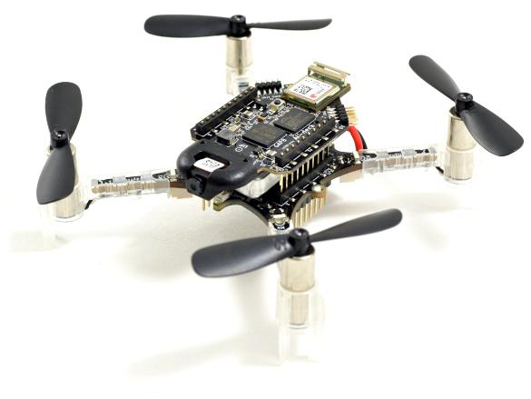
About a month ago we released the AIdeck 1.1, which has some slight upgrades and changes compared to the 1.0. Even though the AIdeck 1.1 is still in early access, we do see the number of support questions increase on our forum and in the issue list of the AIdeck example repo. Therefore we are planning to host an AI-deck getting-started workshop by the PULP lab on the 16th of April at 14:00 (Central European Summer time)!
PULP
The PULP lab has done many amazing research on the field of Edge ML and were one of the collaborators in the development of the AI-deck of which their work on the Pulp Shield was the main inspiration. For more information check out their guest blogpost and be sure to read their latest work on the AI-deck!
More over, they have been working on an opensource tools that also work on the GAP8chip which are must try-outs for any AI-deck users
- DORY: Deployment ORiented to memorY (Github, Paper)
- NEMO: NEural Minimizer for pytOrch (Github, Paper)
- PULP dronet (Github, Paper)
All in all, since they clearly know what they are talking about, they are more than qualified to teach the rest of us how to work with all this! Also check out Luca Benini’s keynote at RISC-V or this week at the TinyML summit if you would like to learn more about PULP!
Date and content Workshop
The workshop will be tailored to those that have just started to to work with the AI-deck however, we think it will be interesting for regular users as well. Note that the tools mentioned above will not be handled this time.
These are the topics that will be discussed:
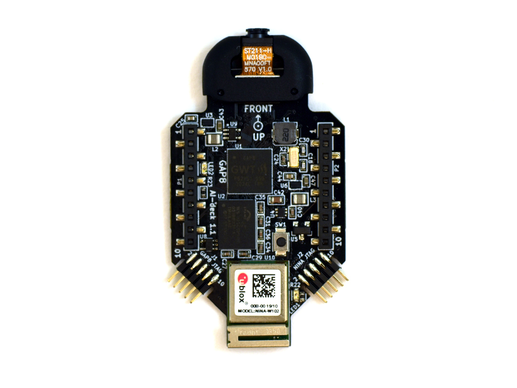
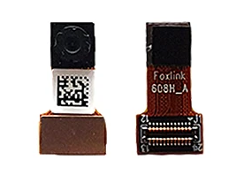
- Hardware explanation (Gap8 specifics and AIdeck)
- Software Preliminaries (GapSDK,, VM)
- Hands-on examples
The workshop will take approximately 2 hours and will be on 16th of April in the afternoon, but the exact specifics will be given at a later date. So make sure to already block it in your calendar and to sign up for more information!
Sign up for more information
You can sign up to receive more information by giving your email address in this google form. We will also keep you up-to-date on our discord channel and the event page.